Table of Contents. Certificates and approvals Colour palette...52
|
|
|
- Blaise Nelson
- 5 years ago
- Views:
Transcription
1 Table of Contents "krono-plan" facade systems Introduction Facade system Gaps and joints between the Kronoplan laminate panels Corners Visible joints. Aluminium structure + removable rivets Hidden joints. Aluminium structure + SPS adhesive...10 "krono - exterior" balcony balustrades Balcony balustrades. "Kronoplan" laminate application guidelines Fixing HPL panels to balustrades with special bolts and removable rivets Fixing Kronoplan laminate panels to aluminium and steel balustrade sections Balcony partition walls Fixing laminate panels to the sections Fixing balcony partition walls to the sections with special bolts and rivets Examples...20 "krono-compakt" facings Introduction Guidelines on application of Kronocompakt laminates as wall facings Corners Panel-to-panel joints and gaps Visible joints. Aluminium structure + rivets Hidden joints. Aluminium structure + SPS adhesive Kronocompakt safety rails (rivets + screws) Kronocompakt safety rails (SPS adhesive)...30 "krono-box" swimming poll lockers " Krono-box" swimming pool locker families Locker types Dimensions Lockers with a bench system Examples...39 "krono-kabina" cubicles "Krono-kabina" product families Single sanitary cubicles Multiple sanitary cubicles Shower room partition walls Single shower cubicles Multiple shower cubicles...48 Certificates and approvals...50 Colour palette

2 KRONOPLAN Facade systems krono - plan Kronoerg Pustków HPL facade systems 2
 and pressure (9 MPa) conditions.")
3 KRONOPLAN Introduction. The Kronoplan panels are a multi-ply material designed for outdoor applications. It is manufactured through pressing cellulose papers impregnated with phenol and melamine resins under heat (160 C) and pressure (9 MPa) conditions. The outer decor layer is protected with a special UV film to prevent the product from an unfavourable impact of the sunlight. High resistance to weather conditions (e.g. temperature, increased humidity, acid rains) allows the use of the Kronoplan panels in construction industry. Standard dimensions: 2800x1300mm 3050x1300mm 5580x2040mm Panel thickness: 6, 8,10 mm For 2800x1300mm For 3050x1300mm For 5580x1300mm SM - matt and smooth, SQ - glossy BS - orange peel PE - pearly. PR - woodgrain SM - matt and smooth, SQ - glossy, PE - pearly BS - orange peel Typical applications of the "Kronoplan" laminates: facade systems balcony balustrade panels balcony partition walls attic linings arcades bus shelters information boards 3
4 KRONOPLAN Facade system. While assembling a "Kronoplan" laminate facade, one should take the following into account: HPLs tend to change the dimensions depending on the temperature and air humidity. A gap between two neighbouring laminate panels shall be wide enough to account for longitudinal and crosswise linear expansion of the material (2.5mm per running metre) a free ventilation space (min. 20 mm) should be provided between the laminate panel and a thermal insulation layer to avoid steam condensation and panel deformation. ventilation holes should be provided in the top and the bottom area of the facade, as well as by the window openings and doorways to allow the air to flow in easily. the size of the ventilation holes should depend on the local conditions and the height of the facade. The following arrangement is assumed: 2 - min. 52 cm of the hole / 1 running metre for >1m facades 2 - min. 21 cm of the hole / 1 running metre for <1m facades in some locations the ventilation hole diameter can be decreased to 5mm the ventilation holes which diameter exceeds 10mm shall be protected from insects only an aluminium or a galvanised steel sections should be used. Aluminium section Outer wall 4
5 KRONOPLAN Gaps and joints between the Kronoplan laminate panels. Guidelines on gaps and joints: an expansion gap (min. 10mm) should be provided between the Kronoplan panels to allow linear expansion of the material (i.e. 2.5mm/m). Weather conditions (temperature and air humidity) should be also considered. if an expansion gap is bigger than 10mm, a masking shape shall be used or a feather joint shall be made. do not apply an excessive force to assemble the panels. Open gaps Open gaps between external facade panels are exposed to rainwater and moisture penetration. Then, only moisture-proof and corrosion-resistant materials should be used (e.g. aluminium structure and stainless-steel bolts) along with heat-insulating materials protected against a wind impact. Masked gaps If the HPL panels used for the facade system are at least 8mm thick, a feather joint or an half-lap joint (in case of horizontal gaps) can be applied. In this way the gaps between the panels are masked. The minimum dimensional requirements for the feather joint are as follows: Tongue: 2x30mm in case of aluminium tongues 3x30mm in case of HPL tongues Groove: 3.3x15mm in case of Kronoerg tongues (panel thickness - 8 mm) 2.3x15mm in case of aluminium tongues (panel thickness - 8 mm) Half-lap: 21 mm In general, the gaps between the panels should not be filled with putty, which is due to the expansion of the facade panels. Besides, dirt can accumulate at the panel edges, which affects the aesthetics of the facade appearance. b/2 b/2 Strip Section b b b b b b/2 b/2 Feather joint g c b min. 15mm a a i b/2 b/2 b>10mm g>8mm g Open gap a b>10mm, a >3,0mm, c>2,9mm, g>8mm, i > 2,0mm 5
6 KRONOPLAN Corners. In case of the facade corners the finish should depend on the thickness of the Kronoplan HPL panels used. If the thickness is 8 mm at least, aluminium or laminate angle sections can be used. Open joint Aluminium section 5mm 5mm b mm b>5mm Strip Feather joint g b b>5mm b b > 5mm, g > 8mm 6
7 KRONOPLAN Visible joints - rivets. T section 120/52/2 AlMgSi 0.5 F25 Thermal insulation Vapour-permeable film Removable rivet; colour the same as of the HPL panel Drawings Aluminium supporting section T section 120/52/2 + thermal insulation + wind-protection Removable rivets Wall 20mm 7
8 KRONOPLAN Visible joints. Aluminium structure + removable rivets. The high pressure laminates should be fixed to an aluminium supporting structure with AlMG5 or V4A steel rivets. The panel thickness - at least 6 mm. The supporting structure is made of aluminium sections, widely available on the Polish market. The sections are approved by the Institute of Masonry Technology. Panel thickness: at least 6mm Gaps: min. 10mm Rivet hole diameter: rivet diameter + 5 mm; 10 mm for non-fixed points the rivet diameter for fixed points is 5.1mm 0.3mm riveting machine should be used. The distance between the rivet and the panel edge: A = distance between the rivets and the panel edge max. 10-fold panel thickness min. 20 mm B = horizontal rivet-to-rivet distance (see the table) D = vertical rivet-to-rivet distance fixed point Z = panel width non-fixed point X = panel height Max. rivet-to-rivet distances for small buildings Kronoplan HPL panel thickness (mm) 6mm 8mm 10mm 13mm Single-span assembly Multiple-span assembly A A D D Fixed point Non-fixed point D D X D D D D A A B A A B B Z A A 8
9 KRONOPLAN Hidden joint - adhesive. Primer - SPS adhesive Aluminium section Two-side adhesive tape Kronoplan HPL panel 9
10 KRONOPLAN Hidden joints. Aluminium structure + SPS adhesive. The assembly works shall be performed in compliance with the technical requirements for glued joints. It is very important to determine the air humidity and a minimum temperature that allows the assembly works. That is why the following guidelines should be observed: in case of glued joints do not use panels, which area is larger than recommended do not exceed the dimensions recommended for glued joints to increase safety apply two rivets or bolts to the upper part of the KronoplanHPLpanel the gaps between the assembly tapes to be filled with an adhesive can be arranged vertically only Application: buildings, height up to 7m Panel thickness: 6mm Max. HPL panel area: 2 2.5m for Z = 2800 X max = 890 mm for Z = 3050 X = 810 mm max Panel-to-panel gap: min. 10 mm The distance between the rivet and the panel edge: A= distance between the connector (rivet or lacquered bolt) and the panel edge max. 10-fold panel thickness min. 20 mm Z = panel width X = panel height Bolt hole diameter: 8.5mm for spray-painted bolts 7.5mm for bolts with washer or masking cap Minimum dimensions of aluminium sections used to assembly the supporting structure: the section shall be selected depending on the panel weight (structural calculations) the section shall be selected depending on the panel weight (panel joints) aluminium square section A aluminium section assembly tape SPS adhesive X Kronoplan Kronoplan HPL panel thickness Max. rivet-to-rivet (mm) distances for small buildings 6mm 8mm 10mm B Z B Single-span assembly Multiple-span assembly

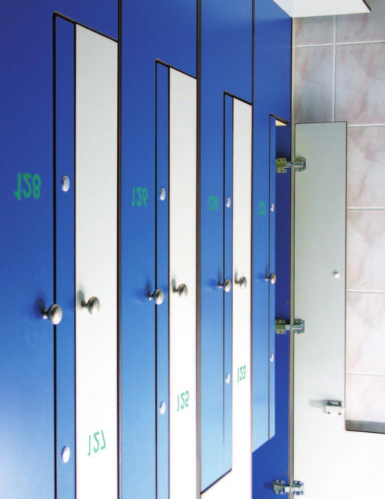
11 KRONOPLAN Balcony balustrades Balcony partition walls krono - exterior "Kronoerg Pustków" HPL balcony balustrade panel systems 11
12 KRONOPLAN Balcony balustrades. "Kronoplan" laminate application guidelines. Before assembling balcony balustrades using HPL Kronoplan panels please read the following notes: only aluminium or galvanised steel sections can be used because of their high resistance to corrosion and durability the optimum height of the balustrade (measured from the balcony floor level to the balustrade rail) depends on the height of the building as per the local regulations while selecting a joint type take the wind pressure into account do not apply excessive force to assemble the HPL panel. Failure to do this may lead to a rupture of the rivet or bolt used for fixing the panel to the supporting structure depending on the HPL panel dimensions the gap between the neighbouring panels shall be at least equal to the panel length x 2.5mm/1m (min. 10 mm) the assembly works shall be performed by qualified personnel 12
13 KRONOPLAN Fixing HPL panels to balustrades with special bolts and removable rivets. The HPL laminate panels are usually fixed to the balcony balustrade using special bolts or removable rivets. The correct layout of the joints shall be calculated on the basis of the assembly data for high pressure laminates. The fixing elements shall have the same colour as the panel (rivets) or should be capped. Panel thickness: at least 6mm Gaps: min. 10mm Rivet hole diameter: rivet diameter + 5 mm; 10 mm for non-fixed points the rivet diameter for fixed points is 5.15mm 0.3mm riveting machine should be used. B = horizontal rivet-to-rivet distance (see the table) max. 20-fold panel thickness min. 20 mm D = vertical rivet-to-rivet distance fixed point C 2 = distance between the balcony floor non-fixed point and the bottom edge of the panel C = the distance between the panel and the balustrade rail (min. 120mm) G = balustrade height depending on the standard requirements Max. rivet-to-rivet distances Single-span assembly Multiple-span assembly Panel thickness (mm) C D D C 2 A A G A B B B A 13
14 KRONOPLAN Fixing Kronoplan laminate panels to aluminium and steel balustrade sections. It is possible to fix even 6mm-thick Kronoplan panels to the balustrade if standard sections are used. In this case the panel shall not be fixed tight to the sections to ensure it rests properly regardless of the weather conditions. That is why the EPDM rubber sections should be used. The dimensions of the aluminium and steel sections should depend on the HPL panel thickness and dimensions. Panel thickness: at least 6 mm The depth of the panel insertion into the section: min. 120 mm Water drain: groove 4x27 mm, in the section Panel edge: free space in the section - min 6 mm C = 1 C = G = H = L = distance between the balcony floor and the bottom edge of the panel the distance between the panel and the balustrade rail (min. 120mm) balustrade height depending on the standard requirements shorter side of the panel longer side of the panel C H G C 1 L 14

15 KRONOPLAN 15
16 KRONOPLAN Balcony partition walls. The balcony partition walls are used in residential multi-apartment buildings to provide each apartment owner with his/her own "box" on the same balcony or terrace. The "krono-exterior" system based on Kronoplan high pressure laminates offers a good solution. The assembly of the partition wall depends on the dimensions of the Kronoplan panel. The examples of such solutions and some further guidelines are given below. Frame - 4 sides Frame - 4 sides Max. spacing L in mm Height / Width ratio Laminate panel thickness (mm) H/L , , , , , , Frame 2 and more sides >2, Minimum thickness of the laminate panel: 6 mm C = distance between the balcony floor and the bottom edge of the panel 2 H H C 2 L L L 16
17 KRONOPLAN Frame - 4 sides (cont.) L/4 H H C 2 L L Fixing laminate panels to the sections Panel thickness (mm) Max. rivet-to-rivet distances (mm) D for single-span assembly 1 Z for multiple-span assembly C 1 = distance between the holder and the edge of the panel C 2 = distance between the balcony floor and the bottom edge of the panel C = distance between the edge of the upper panel and the holder 3 17
18 KRONOPLAN C 1 Z 1 Z 1 Z 1 Z 1 C 1 C 2 D 1 C 1 C 1 C 1 D 1 D 1 C 1 C 3 D 1 /4 Z 1 Z 1 Z 1 Z 1 C 2 e C 1 D 1 C 1 C 1 D 1 C 1 18
19 KRONOPLAN Fixing balcony partition walls to the sections with special bolts and rivets. Max. rivet-to-rivet distance (L) Single-span assembly Multiple-span assembly Panel thickness (mm) C 1 = 149mm (min.) C 2 = 20-fold thickness of the laminate panel (max.) - bolts or rivets H C 2 C 1 L L L C 1 19

20 KRONOPLAN Balcony partition walls - examples 20
21 Facings Safety rails krono compact "Kronoerg Pustków" HPL facings 21
 enables an optimum décor arrangement for any interior - depending on its functionality.")
22 Introduction. Our next proposal is to use the Kronocompakt high pressure laminates as wall facings in public buildings. Wide palette of colours and patterns (including plain, woodgrain and fantasy options) enables an optimum décor arrangement for any interior - depending on its functionality. All laminates for indoor use can be characterised by high scratch resistance and impact strength. They can be kept clean easily and are resistant to moisture environment. Standard dimensions: 2800x1300mm 3050x1300mm 5580x2040mm Panel thickness: 4, 6, 8, 10, 12, 13, 15, 18, 20 mm Krono-compakt finish type: For 2800x1300mm For 3050x1300mm For 5580x1300mm SM - matt and smooth, SQ - glossy, BS - orange peel PE - matt, pearly. PR - woodgrain SM - matt and smooth, SQ - glossy, PE - matt, pearly BS - orange peel Typical applications: schools sports halls and offices hotels hospitals cubicles swimming pool lockers safety rails 22
23 Guidelines on application of Kronocompakt laminates as wall facings. The following guidelines have to be followed: the aluminium or galvanised steel sections should be used because of their high resistance to corrosion it is necessary to leave a 20mm ventilation gap between the Kronocompakt panel and the wall (full height) use fixed and non-fixed points while fixing the panels to a steel or aluminium structure with bolts and rivets all panel-to-panel gaps should be masked do not apply excessive force to assemble the HPL panels with rivets and bolts in case of a glued joint the adhesive shall be distributed uniformly in vertical direction 2 and the laminate panel area should not exceed 2.5m the spacing of the structural elements should depend on the Kronocompakt laminate thickness all electrical and plumbing works should be performed prior to the assembly according to the national standards and regulations. 23
24 Corners. The thickness of the Kronocompakt laminate panels should not be less than 6 mm. Otherwise, a bolt will not sit in the panel properly. Besides, as the Fig. 1 shows, it is necessary to make a 3mm-groove for the aluminium tongue (feather joint). The number and layout of bolts and rivets depends on the spacing of the structure elements. Only materials certified and approved for the construction industry should be used to assemble decor Kronocompakt HPL facings Feather joint (aluminium tongue) Masked corner 6mm 3. Masked corner. Skew inner joint with a square profile 4. Masked corner. Straight outer joint with an aluminium profile min 6mm 24
25 Panel-to-panel joints and gaps. The gaps between the neighbouring panels should be masked or filled with a proper sealing material. Typical solutions are presented below. The most popular horizontal solution is a halflap joint. In case of vertical solutions the most popular are the feather joint or a so-called "false feather" joint. In the latter solution a flat aluminium bar (up to 2mm thick) is used. The bar is painted in the same colour as the HPL panel. 1 Half-lap joint 2 Half -lap joint + sealing material 3 Feather joint with sealing material and a flat aluminium bar 4 Feather joint + sealing material and a 3mm-thick laminate tongue 25
26 Visible joints. Aluminium structure + removable rivets. To make a wall facing the high pressure laminate panels should be fixed to an aluminium supporting structure with AlMG5 or V4A steel rivets. The panel thickness - at least 6 mm. The supporting structure is made of aluminium sections, widely available on the Polish market. The sections are approved by the Institute of Masonry Technology. Panel thickness: at least 6mm Gaps: min. 10mm (masked) Rivet hole diameter: rivet diameter + 5 mm; 10 mm for non-fixed points the rivet diameter for fixed points is 5.15mm 0.3mm riveting machine should be used. B = horizontal rivet-to-rivet distance (see the table) A = distance between the rivets and the panel edge max. 10-fold panel thickness min. 20 mm D = vertical rivet-to-rivet distance fixed point Z = panel width non-fixed point X = panel height Max. rivet-to-rivet distances for small buildings Single-span assembly Multiple-span assembly Kronocompakt HPL panel thickness 6mm 8mm 10mm 13mm A A D D Fixed point Non-fixed point D D X D D D D A B A A A B B A A Z 26
27 Hidden joints. Aluminium structure + SPS adhesive. The Kronocompakt HPL wall facing assembly works shall be performed in compliance with the technical requirements for glued joints. It is very important to determine the air humidity and a minimum temperature that allows the assembly works. That is why the following guidelines should be observed: the gaps between the assembly tapes to be filled with an adhesive can be arranged vertically only do not exceed the Kronocompakt panel dimensions recommended for glued joints adhere to manufacturer's instructions for SPS adhesive and high pressure laminates Application: indoor wall facings Panel thickness: from 4mm Panel-to-panel gap: min. 10 mm (masked) Max. HPL panel area: 2 2.5m for Z = 2800 X max = 890 mm for Z = 3050 X = 810 mm The distance between the rivet and the panel edge: A = distance between the connector (rivet or lacquered bolt) and the panel edge max. 10-fold panel thickness min. 20 mm B = horizontal rivet-to-rivet distance (see the table) max Z = panel width X = panel height Bolt hole diameter: 8.5mm for spray-painted bolts 7.5mm for bolts with washer or masking cap Minimum dimensions of aluminium sections used to assembly the supporting structure: aluminium section 50x30x2.5mm aluminium section (panel-to-panel joints) 85x30x2mm A aluminium section assembly tape SPS adhesive X Kronocompakt Max. rivet-to-rivet distances for small buildings Kronoplan HPL panel thickness 6mm 8mm 10mm B Z B Single-span assembly Multiple-span assembly
28 Kronocompakt safety rails (rivets + screws). 6mm mm 400mm min. 20mm m depending on the panel thickness mm Wall 2. Floor 3. Kronocompakt safety rail 4. Fixed point + connectors (rivets or screws) 5. Aluminium section 6. Aluminium angle section 7. HPL tongue, 3mm thick 8. HPL bar 9. Non-fixed points 28
29 Kronocompakt safety rails (rivets + screws). The laminate panels for the safety rails should not be thinner than 8 mm. The layout of aluminium sections, which the panels are fixed to, depends on the thickness of the panels and should be between 440mm and 1190mm. The neighbouring safety rail units are joint using a 3mm-thick HPL feather joint (see: "Panel-to-panel joints and gaps", Example 3 and 4). This solution requires a free space in the centre of the panel thickness for the laminate tongue. Such a requirement results from the properties of the panel material. All safety rail edges should be rounded using a milling machine with concave knives. Each safety rail unit should be provided with one fixed assembly point. Other locations where the rail is fixed to the aluminium structure should be non-fixed points. The difference lies in the rivet hole diameter in the panel and in the aluminium section, as depicted below: Fixed point Non-fixed point The stress distribution in the laminate panel depends on the location of the fixed point: 29
30 Kronocompakt safety rails (SPS adhesive) mm mm 400mm mm m depending on the panel thickness Wall 2. Floor 3. Kronocompakt safety rail 4. SPS adhesive 5. Aluminium section 6. Aluminium angle section 7. HPL tongue, 3mm thick 8. HPL bar 30

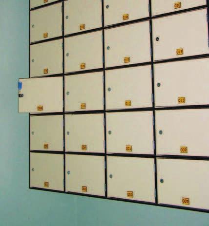
31 Swimming pool lockers krono box "Kronoerg Pustków" HPL swimming pool locker systems 31
32 Swimming pool lockers. "Krono-box" swimming pool locker families. Single Multiple Top view 32
33 Locker types. Single locker - S1 type Swimming pool locker - S2,, Sn type n - number pf compartments Swimming pool locker - L2 type Swimming pool locker - S3 type Swimming pool locker - S4 type 33
34 Dimensions of single and multiple lockers. Swimming pool locker - S4 type 3S1 1800mm 50mm 318mm 918mm Swimming pool locker S2 3S2 900mm 900mm 50mm 318mm 918mm 34
35 Single locker S3 3S3 600mm 600mm 600mm 50mm 318mm 918mm Swimming pool locker S4 3S4 450mm 450mm 450mm 450mm 50mm 318mm 918mm 35
36 Swimming pool locker L2 3 L2 400mm 1400mm 50mm 318mm 318mm 318mm 318mm Locker description: door, base - HPL panel, 10 mm rear wall - HPL panel, 3mm shelves, top - HPL panel, 10 mm stainless steel hinges, not accessible from the outside to protect the locker from breaking the door down (or an electronic locking system upon customer's request) pegs and other accessories upon customer's request During the assembly works the lockers are combined in sets. The number of sets and the number of lockers per set is not limited. The standard dimensions of a set including one, two or three lockers are: width 260, 300, 400 mm (other sizes upon request) depth 500 mm height 1800 mm plus the base 50 mm 36
37 Lockers with a bench system 400mm 400mm 400mm 400mm 37
38 Side view (locker with a bench) 400mm mm 1400mm 10mm 50mm mm 400mm mm 1000mm 400mm 1800mm 1. Supporting structure made of galvanised steel sections 2. L2 locker made of Kronocompakt HPL 3. Kronocompakt, thickness 10 mm, as a bench 4. Adjustable feet cm-deep cavity for the locker base 38

39 Examples 39
40 40

41 Cubicles krono kabina "Kronoerg Pustków" HPL cubicles 41
42 Cubicles. "Krono-kabina" product families. Single Multiple Views 1300 mm 100mm 800mm 100mm 100mm 800mm 200mm 800mm 100mm (900mm) (900mm) (900mm) 42
43 Single sanitary cubicles - modules. S1 type View 150 mm 1850 mm 20 mm 100mm 800mm 100mm (900mm) SC type View 150 mm 1850 mm 20 mm 100mm 800mm 100mm (900mm) 43
44 SP type View 150 mm 1850 mm 20 mm 100mm 800mm (900mm) 100mm Multiple sanitary cubicles - modules n SL type View 1850 mm 20 mm n - number of cubicles 150 mm 100mm 800mm 200mm 800mm 100mm (900mm) (900mm) 44
45 n SC type View 1850mm 20mm n - number of cubicles 150mm 100mm 800mm 200mm 800mm 100mm (900mm) (900mm) n SP type View 1850mm 20mm n - number of cubicles 150mm 100mm 800mm 200mm 800mm 100mm (900mm) (900mm) 45
46 Shower room partition walls. Made of Kronocompact" laminate, thickness: 10 mm or 13mm. Shower hardware similar to that of the sanitary cubicles. Single Multiple mm 1300 mm mm 800mm 100mm 100mm 800mm 200mm 800mm 100mm (900mm) (900mm) (900mm) 1. Shower tub 2. Kronocompakt partition walls mounted with standard brackets 3. Curtain 46
47 Single shower cubicles - modules. NL type View 1850mm 20mm 150mm 100mm 800mm 100mm (900mm) NC type View 1850mm 20mm 150mm 100mm 800mm 100mm (900mm) 47
48 NP type View 150mm 1850mm 20mm 100mm 800mm 100mm (900mm) Multiple shower cubicles - modules. n NL type View 1850mm 20mm n - number of cubicles 150mm 100mm 800mm 200mm 800mm 100mm (900mm) (900mm) 48
49 n NC type View 1850mm 20mm n - number of cubicles 150mm 100mm 800mm 200mm 800mm 100mm (900mm) (900mm) n NP type View 150mm 1850mm 20mm n - number of cubicles 100mm 800mm 200mm 800mm 100mm (900mm) (900mm) 49