Glen A Harvey. Agenda. Overview of different roll cover materials, Construction Factors considered for cover selection
|
|
|
- Derrick Park
- 5 years ago
- Views:
Transcription


1 Glen A Harvey Director Rolls Engineering Technology NA Agenda Roll Covers Overview of different roll cover materials, Construction Factors considered for cover selection Press Optimization TIPS Effective Void Volume Innovations and cases studies SMART ROLL 1
2 Why do we cover a roll? Protect the roll core Vibration dampening Traction (slippage of sheet) Release properties Pressure Intensity of a nip Clothing wear Sheet Characteristics Quality of sheet Improved drainage (open area of roll) Roll Cover Materials Rubber Polyurethane Composite 2
3 Rubber Cover Technology Typical Rubber Cover Construction TOP STOCK TIE-IN BASE CORE 3
4 Effects of Press Loading A rubber cover does not compress It is displaced and assumes a different shape Nip width is dependant upon modulus, thickness and load Nip loading exerts both compressive and shear stresses on the cover Bonding system must be able to withstand the shear stress force found at the bond line Unloaded Loaded Typical Press Roll Cover Base Construction Rubber Cover PLI Rubber Cover PLI & Suction Rubber Cover > 800 PLI Topstock thks as required.125 Tie in.125 Base Topstock thks as required.125 Tie in.1875 Base Topstock thks as required.125 Tie in.250 Base = Cement Layer 4
5 Bases Three Primary Functions Provides a high modulus material for optimum mechanical bonding strength. High hoop strength Minimize shear stress at core / base interface Creates a modulus (psi) transition between the lower modulus top stock / tie-in and the high modulus core Retards moisture permeation to the core Base Options Standard Bases Co-cured or pre-cured/pre-ground (majority co-cured) Chemical bonding with co-cured system 150 F bond line temperature limit Bond strength degrades as temperature increases Heat Transfer calculations are run for water cooling requirements 5
6 Base Options Lifegard I Composite base, very high hoop strength 185 F bond line temperature capability Minimize or eliminate water cooling Specific water cooling temperature requirements Lifegard II 240 F bond line temperature capability High bond strength at elevated temperatures Eliminate water cooling Top Stock may now be the limiting factor for temperature Tie-in Rubber Covers Intermediate layer between base and top-stock Typically a mix of base stock and top stock material to provide a good chemical bond. Provides an intermediate modulus layer between the top stock and base decreasing possibility of sheer stress failure at high modulus/low modulus interface. Top Stock Tie-in Base Core 6


7 9/26/2013 Compounding and Mixing 2-roll mills used to blend rubber components Accurate cover specifications are essential to ensure the proper recipe for the desired cover properties Core Preparation Blasting Cementing Increases core surface area for improved bond Promotes adhesion of base to core 7


8 Rubber Covering Extruding Wrapping Curing Vulcanization Reverse inside steam steam flowing through core. Note that roll heads must have vent holes and those holes must be plugged prior to shipping roll. 8


9 9/26/2013 Grinding, Drilling, Grooving, Balancing Reassembly, Paint, Wrap, Ship Accurate bearing, grease and paint specifications are essential. 9
10 Polyurethane Technology Polyurethane Working Rolls Incline Cast JetCast Rotational Cast 10

11 Typical Press Roll Cover Base Construction Rubber Cover PLI Rubber Cover PLI & Suction Rubber Cover > 800 PLI Topstock thks as required.125 Tie in.125 Base Topstock thks as required.125 Tie in.1875 Base Topstock thks as required.125 Tie in.250 Base Polyurethane Cover Non-suction Polyurethane Cover Suction Topstock thks as required.1875 Epoxy Base Topstock thks as required.250 Epoxy Base = Cement Layer Rotational Cast Developed by SW Sweden Single pass application Many advantages Fast manufacturing process Elimination of molds Elimination of oversize waste Elimination of mold release Superior physical properties equal to or better than mold cast Possible reduction in rejects and warranties 11
12 9/26/2013 Polyurethane Machine Composite Roll Covers 12


13 Composite Cover Construction Top stock: Fiber reinforced epoxy with various filler systems..300 thick. Generally Shore D Hardness Base Layer: Fiber reinforced epoxy..200 thick Topstock Base Layer Steel Core Side Total Thickness =.500 per side Manufacturing: Wrap / Lamination Process 13
14 Factors considered for cover selection Critical Roll Cover Performance Properties 1. Hardness static modulus 2. Dynamic modulus 3. Hysteresis 4. Moisture diffusion 5. Chemical resistance 6. Release properties 7. Abrasion resistance 8. Mark Resistance 9. Crack Resistance 11. Coefficient of Friction 12. Temperature capabilities 13. Hardening properties 14. Effect of thickness 15. Vibration dampening properties 16. Residual stress 17. Machining capabilities Water Diffusion in Roll Covers Concentration Gradient: Immersed cover sample will absorb water until the concentration gradient disappears and the cover reaches saturation Concentration Gradient Cover Sample 14


15 Water Diffusion in Roll Covers Temperature Gradient forces water to the cooler side and can result in Supersaturation-water in excess of saturation. Temperature Gradient Surface 115 F Internal Water Cooling 75 F Topstock Base Steel Core Water Diffusion Failure Moisture Diffusion / Channeling Failure Small fingernail shaped surface cracks As the cover is tooled away, the cracks are found to open up into channels that spiral around the cover Many additional channeling areas are revealed at base Cover Removal Process in Steps 15
16 Press Optimization TIPS - Total Innovative Press Solutions 1. Establish performance and quality objectives 2. Analyze current operating conditions and capabilities 3. Establish appropriate dewatering theory for specific grade and machine design 4. Design roll covers to create optimum nip intensity and width 5. Design felts to handle water, transfer sheet and for pressing uniformity and sheet smoothness 6. Design cover venting to compliment felt design and dewatering theory Pressure Total nip pressure Paper structure pressure Hydraulic pressure Press / Nip length 16


17 TIPS - Objective Optimizing machine conditions and performance to achieve a predetermined set of goals Press Studies have to be Objective driven Production Goals Increase moisture removal Speed Increase Run-ability Holes reduction Blowing Moisture profile Basis weight Faster start up Breaks Drop offs Edge flipping Vibration Cost Reductions Fiber reduction Increased felt life Energy savings Water savings Maintenance cost Felt Installation time Chemical cleaner Sheet Qualities (Tests) Bulk / Smoothness / Caliper Strength properties Internal bond Shadow marking Picking and linting De-fiberization energy Softness Seam mark Batt felt mark Base fabric mark TIPS - Total Innovative Press Solutions Determine recommended pressure range from application guidelines based on: 40 years of practical experience Paper grade / Desired sheet properties Press configuration Incoming solids Max load normal load = Lost Impulse Sheet densification Crushing Poor felt performance Poor run-ability 17
18 TIPS - Philosophy Impulse is the driving force in sheet dewatering Impulse = Load (Kn/m, PLI) Speed (mpm, fpm) Develop ideal nip conditions at the optimal press Impulse. Maximize moisture removal Protect sheet qualities Sustain performance of rolls and felts Sheet Felt Nip Curve Hydraulic Pressure TIPS - Optimize All Press Nips Design press nips to compliment other nips for the best dewatering efficiency and sheet quality Engineer covers to produce incremental pressure increases between presses at full load Maintain nip peak pressures at proper levels to maximize nip width and dwell time Nip Peak Pressure and Cumulative Nip Width Kn/m 900 PLI Original Arrangement 2 nd Press 3 rd Press 4 th Press 4 th Press 105 Kn/m 600 PLI 3 rd Press 1 st Press 2 nd Press 52.5 Kn/m Optimized Design 300 PLI 1 st Press Example of existing machine mm 2 inches 102 mm 4 inches 152 mm 6 inches 18
19 Benefits / Deliverables Improved sheet qualities Caliper / bulk Strength tests Smoothness Improved paper machine performance Increased sheet solids Reduce steam usage Incremental speed Fiber Savings Sustained performance of press felts Less wear to roll covers Effective Void Volume 19


20 Venting Options Grooved Dri-Press - Engineered Blind Drilling Dri-Press and Grooved Suction Suction Double Drilled Suction Grooved Suction Dri-Press / Suction Blind Drilled Suction Dri-Press Grooved Engineering Nip Venting Dri-Press patterns have been designed to provide the most uniform open area Pattern # Open Area Typical Dri-Press Patterns Hole Diameter Land Distance A Land Distance B Land Distance C 14 25% % % % % New patterns: No. 32 and No. 50 with and hole diameters and approx. 25% open area All patterns have a grooving option and all patterns can be engineered with all holes intersecting a groove 20


 Suction")


21 Engineered Nip Venting Pattern Hole Diameter 25% Open Area Pattern Hole Diameter 32% Open Area Pattern Hole Diameter 25% Open Area Engineered Suction Venting Patterns Suction 14 18% OA (23-27% double drilled) Suction Dri-Press 25-31% OA Suction Grooved Up to 35% OA Suction Dri-Press Grooved Up to 44% OA 21


22 Suction Roll Evaluation Board and Pulp Cover softness not suitable for grooving Changed suction roll from straight drilling to double drilling Suction open area opened from 17% to 32% Vacuum system, pans and doctors were evaluated first for water handling capability Felt was evaluated for flow rate tolerance Application Benefits 1% increase in press solids into dryer Engineering Value Coordination Cover design sets nip conditions Felt design controls sheet smoothness and influences press performance Engineered venting compliments felt design Recent example Reengineered cover for appropriate nip pressure Evaluation kept existing felt design Redesigned grooving pattern to reduce flow restriction and increase void volume Value Improved sheet quality Higher press solids / 5% speed increase $3 million Value Results 1000 PLI Grooved Bottom Now: 8 GPI Wide x Deep Was: 10 GPI Wide x Deep 22


23 1 st Press Builds 2 nd Press Performance Engineered venting improved tandem felt performance Traditionally blind drilled bottom rolls Redesigned 1 st press bottom venting to improve 2 nd press performance. 1 st press bottom changed to partial nip dewatering More felt void volume entering 2 nd Nip Less hydraulic forces in 2 nd press Application Benefits Customer A : ton/hour increase Customer B : 15 FPM increase on all grades Now: Blind Drilled Grooved 35% Open Was: Blind Drilled 21% Open Hydrophobic Cover Material 23

24 Development of Surface Properties Super-hydrophobic surface properties Non-plugging, clean running Support for water handling concepts Doctor elimination potential Primary Press Innovations Soft Covers Over Grooved Rolls Superior soft cover materials in top positions generate proper nip intensities while hard grooved bottom roll that allows the moisture to escape the nip. The open area reduces the hydraulic forces and allows optimal loading. 24


25 Soft Covers Over Grooved Rolls Install 70 P&J top primary roll covers Grooved 3 bottom primary rolls Increased press load on 1 st primary 190 PLI Increase dwell time: 116% 1 st, 30% 2 nd, 22% 3 rd, 17% main Install 24 P&J, 1 thick cover with LGII base in main Increase main press load 100 PLI Opened primary felts for better water removal 2% Reduction WEM = 6% production Increase Maintain sheet bulk / density $198,000 / year value Polyurethane and Rubber Advancements Super low hysteresis - cooler under pressure Long run life with superior abrasion resistance Superior ability to withstand wad impacts High performance bonding system Drier performance with greater stability Runs clean with less wax build-up and hole plugging 25


26 Polyurethane and Rubber Advancements Unique high performance polyurethane and rubber elastomers run cooler Increased bond strength from lower operating temperature More tolerant of biased loads Extractor to Main Press 4% increase in speed Improved efficiency Improved ply bond $ Covers are old, thin and harder than original covers Generates higher nip intensity and less dwell time Re-establish original condition begin w/ extractor 26
27 New Concepts for Maximum Performance, Reliability, Life Aquarius Armor Soft rubber base produces low nip intensity and wide nip width Harder thin poly top offers hardness and chemical stability, superior abrasion resistance, and release Harder Shell Poly Top Coat Soft Rubber Substrate Consistent operation minimal change in hardness, thickness or CD uniformity Minimal maintenance 1 to 2 long runs reduces handling, grinding, and freight costs 27
28 28

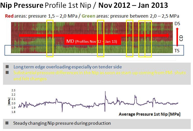
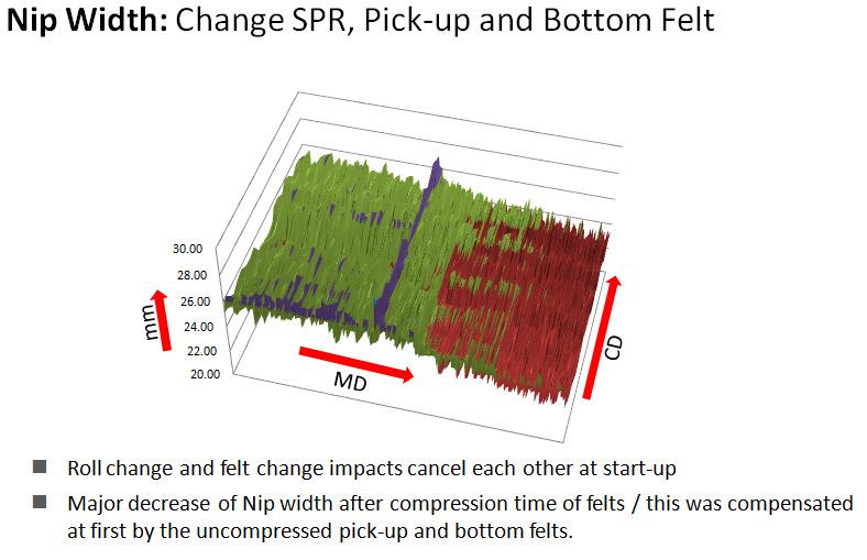
29 Nip width and nip pressure CD history Standard deviation Shoe Press Application First ever real time impulse curve from a shoe press nip 29
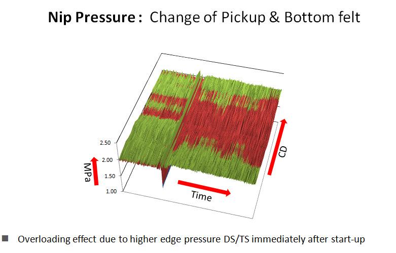
30 30
31 31
32 32

33 Roll Technology Customer : East Coast NA Position : Suction Drum Rider Roll (SMART Roll) Speed : 700 fpm, 215 mpm Grade : Packaging Press load : pli Cover : Aquarius with Hardness : 110 P&J Performance SMART Roll technology allowed the mill to have consistent nip profiles Improved sheet caliper profile Felt usage reduced from 10 felts annually to 4 felts annually ValueResults signed off for $60,000 per year! Mid-West Board Machine Value Results $980,196 /Year Incremental Tons Steam Savings Record Year Record Pace Proper Nip Intensity at Optimal Impulse Additional 960 PLI Incremental Increase Between Presses 29% Increase - Total Nip Width Engineered Venting 33


34 White Pigeon Paper Company Forming Section 34


35 PRIMARY PRESS PLI TOP FELTED TOP & BOTT ROLLS BLIND DRILLED SUCTION 26 25% SOLIDS OLD TOP ROLL 70 P & J BOTT ROLL 35 P & J NEW TOP ROLL 120 P & J BOTT ROLL 60 P & J 35

36 VR PRESS 250 PLI TOP FELTED TOP ROLL BLIND DRILLED BOTTOM ROLL BLIND DRILLED WITH SUCTION SIDE ROLL SMOOTH % SOLIDS OLD TOP ROLL SUCTION TOP ROLL 35 P & J BOTT ROLL 45 P & J SIDE ROLL 1 P & J NEW NO SUCTION TOP ROLL TOP ROLL 50 P & J BOTT ROLL 55 P & J SIDE ROLL 1 P & J SECOND PRESS 1000 PLI TOP & BOTT FELTED TOP & BOTT ROLLS BLIND DRILLED % SOLIDS TOP AND BOTT 20 P & J 36

37 THIRD PRESS 42 48% SOLIDS 2000 PLI BOTT FELTED TOP ROLL SMOOTH BOTT ROLL BLIND DRILLED 42 FINISHED O.D. 42 TOP AND BOTT 20 P & J Summary Softer Nips in 1 st Primary and VR Press Removed suction from VR Press top roll Overall improved machine runnability Increased production of 8% 37
38 Press Optimization Summary Define operating objectives and limitations Select recommended pressure range Choose the proper cover material Top stock and base Cover thickness to develop proper nip intensity at optimal press impulse Develop incremental increase in nip intensity Utilize most effective void volume Press Optimization Summary Soft over Grooved Low hysteretic material Begin at extractors Keep roll covers in like new condition Smart Technology for additional operating insight and improved qualities Design felts to compliment conditions Handle the water Transfer the sheet, Pressing uniformity Improve sheet smoothness 38