Submittal / Substitution Request
|
|
|
- Allison McCormick
- 5 years ago
- Views:
Transcription
1 Submittal / Substitution Request SUBMITTED TO: To: Firm: Project: Submitted Product: SIMPSON STRONG-TIE STRONG-BOLT 2 Wedge Anchor for Cracked and Uncracked Concrete Specified Product: Section: Page: Detail/Sheet No.: Description of Application: Attached information includes product description, installation instructions and pertinent technical data needed for evaluation of the submittal request. SUBMITTED BY: Name: Signature: Firm: Address: Phone: Fax: Date of Submittal: FOR ARCHITECT/ENGINEER USE: Approved: Approved As Noted: Not Approved: (Please briefly explain why not approved) Cracked & Uncracked CONCRETE By: Date: Remarks: ICC-ES ESR-07 IBC SIMPSON STRONG-TIE COMPANY INC. T-SAS-STB2SUB 4/ Exp. 6/2
2 Table of Contents Simpson Strong-Tie Strong-Bolt 2 Wedge Anchor Technical Information Anchor Software Selector for ACI 8 Information ICC-ES ESR-07 State of Florida approval number FL-06.6 To view the approval, visit our website at (under Information & Downloads Documents Code Reports) or access the Florida Department of Community Affairs website at Mechanical Anchors Material Safety Data Sheet 2


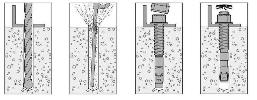
3 Anchoring and Fastening Systems for Concrete and Masonry Addendum Strong Bolt 2 Wedge Anchor The Strong-Bolt 2 wedge anchor is the next-generation solution for cracked and uncracked concrete. Following rigorous testing according to ICC-ES acceptance criteria, the Strong-Bolt 2 anchor received classification as a Category anchor, the highest attainable anchor category for performance in cracked concrete under static and seismic loading. Available in stainless steel, it is code-listed by ICC-ES under the 2009 IBC requirements for post-installed anchors in cracked and uncracked concrete. FEATURES: Category anchor classification: The Strong-Bolt 2 anchor received classiication as a Category anchor, which is established by performance in reliability tests in accordance with AC9 and ACI.2 test criteria. Category is the highest attainable anchor category for reliability. Tri-segmented clip: Each segment adjusts independently, increasing follow-up expansion should the hole increase in size as a result of a crack Dual embossments on each clip segment: Enables clip to undercut into the concrete thereby increasing follow-up expansion should a crack occur The only " anchor solution approved for 4" concrete thickness: The Strong-Bolt 2 anchor can be installed in cracked concrete with a minimum thickness of ¼", including concrete-over-metal decking High-strength alloy clip on carbon-steel anchors: This special alloy clip offers improved performance Standard (ANSI) fractional anchor: Fits most ixtures and installs with common drill bit sizes and tools Easy post-installation identification: The head is stamped with Simpson Strong-Tie symbol and a letter for length identiication Type 6 stainless-steel clip on stainless steel anchors: In addition to superior corrosion resistance, a stainless-steel clip offers memory that contributes to the anchor s performance if the hole increases in size because of a crack Strong-Bolt 2 Wedge Anchor Installation Sequence Head Stamp The head is stamped with the Simpson Strong-Tie No-Equal symbol and the length identification letter. MATERIAL: Carbon-steel stud with special alloy clip; stainless-steel stud with stainless-steel clip ( " diameter only) FINISH: Zinc-plated (carbon steel) CODES: ICC-ES ESR-07 (carbon and stainless steel); City of Los Angeles Pending; UL Pending; FM Pending; Florida Pending TEST CRITERIA: The Strong-Bolt 2 wedge anchor has been tested in accordance with ICC-ES s Acceptance Criteria for Mechanical Anchors in Concrete Elements (AC 9) and ACI.2 for the following: Static tension and shear loading in cracked and uncracked concrete Seismic and wind loading in cracked and uncracked concrete Performance in cracked concrete Performance in lightweight concrete over metal deck NOTE PRODUCT AVAILABILITY AS FOLLOWS: STB2 "- diameter in carbon steel, stainless steel: irst quarter 20 STB2 2"- and "-diameter in carbon steel: second quarter 20 Length Identification Head Marks on Strong-Bolt TM 2 Wedge Anchors (corresponds to length of anchor inches) Mark Units A B C D E F G H I J K L M N O P Q R S T U V W X Y Z From Up To But Not Including
4 Anchoring and Fastening Systems for Concrete and Masonry Addendum Strong Bolt 2 Wedge Anchor Product Information Strong-Bolt 2 Anchor Product Data Size () Carbon Steel Model No. 6 Stainless Steel Model No. Drill Bit Dia. () Thread length () Box Quantity Carton x 2 4 STB2-724 STB2-7246SS x STB2-700 STB2-7006SS x 2 STB2-72 STB2-726SS x 4 STB2-74 STB2-746SS x STB2-700 STB2-7006SS x 7 STB STB SS x 4 STB x 4 4 STB x 2 STB x 7 STB x 8 2 STB x 0 STB x 4 2 STB x STB x 6 STB x 7 STB x 8 2 STB x 0 STB Material Specifications Anchor Body Carbon Steel Carbon Steel - Zinc Plated Component Materials Nut Washer Clip Carbon Steel ASTM A 6, Grade A Carbon Steel ASTM F844. Zinc meets ASTM B 6, Class SC (Fe / Zn ), Type III. Anchor Body Type 6 Stainless Steel Stainless Steel Component Materials Carbon Steel ASTM A 68 Nut Washer Clip Type 6 Stainless Steel Type 6 Stainless Steel Type 6 Stainless Steel Strong-Bolt 2 Installation Information Characteristic Symbol Units Nominal Anchor Diameter () Carbon Steel Stainless Steel 8 Installation Information Nominal Diameter d a 2 Drill Bit Diameter d 2 Baseplate Clearance Hole Diameter 2 d c Installation Torque T inst ft-lbf (N-m) Nominal Embedment Depth h nom Effective Embedment Depth h ef Minimum Overall Anchor Length l anch Critical Edge Distance c ac Minimum Edge Distance Minimum Spacing c min for s s min for c Minimum Concrete Thickness h min Yield Strength f ya psi (MPa) Tensile Strength f uta 4 psi (MPa) Minimum Tensile and Shear Stress Area A se in 2 (mm 2 ) Axial Stiffness in Service Load Range Cracked and Uncracked Concrete β lb./in (N/mm) 2 () (4) 2 4 (70) 6 2 (6) 4 (8) 7 6 (.) 0 (40.7) 6 (2) (76) 2 7 (7) 2 2 (64) 2 (89) 6 (2) 4 2 (4) Additional Data 92,000 (64) 0.04 () 4,820 (6,098) 6 2 (6) 7 (78) 7 (78) 4 2 (4) 2 4 (70) 2 4 (7) 4 (9) For SI: inch = 2.4 mm, ft-lbf =.6 N-m, psi = 6.89 Pa, in 2 = 64 mm 2, lbf/in = 0.7 N/mm.. The information presented in this table is to be used in conjunction with the design criteria of ACI 8 Appendix D. 2. The clearance must comply with applicable code requirements for the connected element.. For the 2006 IBC, d o replaces d a. 4. For the 200 IBC, f ut replaces f uta.. Drilled hole depth to be greater than or equal to nominal embedment depth (4.) 60 (8.) 6 2 (6) 4 (02) 4 (02) 2 (40),000 (79) 0.0 (68) 6,70 (,) 7 (98) (86) 2 (40) 7 2 (9) 4 (02) 4 (02) 6 (2) 8,000 (86) (86) 2 4 (70) 4 2 (4) 7 2 (9) 2 (40) 6 (7.) 90 (22.0) 6 2 (6) (27) 0.66 (07) 9,70 (6,00) (0) 4 2 (4) 6 (2) 9 (229) 7 7 (200) 2 () (4) 2 4 (70) 6 2 (6) 4 (8) 7 6 (.) 0 (40.7) 6 (2) 0 (24) (76) 0 (24) 80,000 (2) 00,000 (689) 0.04 () 29,0 (,0) 2 7 (7) 2 2 (64) 2 (89) 8 2 (26) 4 2 (4)
5 Anchoring and Fastening Systems for Concrete and Masonry Addendum Strong Bolt 2 Wedge Anchor Performance Data Strong-Bolt 2 Wedge Anchor Tension Strength Design Data Characteristic Symbol Units Nominal Anchor Diameter () Carbon Steel * *See page for an explanation of the load table icons Stainless Steel 2 Anchor Category,2 or Nominal Embedment Depth h nom Steel Strength in Tension N sa lb (kn) 2 () 2 7 (7) 2 4 (70) Steel Strength in Tension (ACI 8 Section D..),600 (24.9) Strength Reduction Factor Steel Failure 2 sa Effective Embedment Depth h ef Critical Edge Distance c ac Effectiveness Factor Uncracked Concrete Effectiveness Factor Cracked Concrete 2,00 (.8) 7 (98) Concrete Breakout Strength in Tension (ACI 8 Section D..2) (4) 6 2 (6) 2 2 (64) 6 (2) 2 4 (7) 6 2 (6) (86) 7 2 (9) (86) 2 4 (70) 7 2 (9) 9,070 (84.8) (0) 4 2 (4) 9 (229) 2 () (4) 6 2 (6) k uncr k cr Modiication Factor ψ c,n Strength Reduction Factor Concrete Breakout Failure cb Pull-Out Strength Cracked Concrete (f c = 200 psi) Pull-Out Strength Uncracked Concrete (f c = 200 psi) N p,cr N p,uncr Pull-Out Strength in Tension (ACI 8 Section D..) lb (kn) lb (kn),40 (22.9) 2 7 (7) 2 2 (64) 8 2 (26),00 (.8) 2,77 (2.) N/A 4,7 (6.6) N/A 4 6,89 (0.7),720 6 (7.7) 6,4 6 (4.0) 6 N/A 4,40 (4.9),6 (6.),2 (2.4) N/A 4 9,02 (40.) N/A 4 4,770 6 (2.2) 6 Strength Reduction Factor Pullout Failure 7 p Tension Strength of Single Anchor for Seismic Loads (f c = 200 psi) N p,eq Tensile Strength for Seismic Applications (ACI Section D...) lb (kn),00 (.8) 2,77 (2.) N/A 4,7 (6.6) N/A 4 6,89 (0.7),720 6 (7.7) 6 2,80 6 (2.6) 6 Strength Reduction Factor Pullout Failure 7 eq For SI: inch = 2.4 mm, lbf = 4.4 N.. The information presented in this table must be used in conjunction with the design criteria of ACI 8 Appendix D, except as modiied below. 2. The tabulated value of sa applies when the load combinations of Section of the IBC, or ACI 8 Section 9.2 are used. If the load combinations of ACI 8 Appendix C are used, the appropriate value of sa must be determined in accordance with ACI 8 D.4.. Strong-Bolt 2 anchors are ductile steel elements as deined in ACI 8 D... The tabulated value of cb applies when both the load combinations of Section of the IBC, or ACI 8 Section 9.2 are used and the requirements of ACI 8 Section D.4.4(c) for Condition B are met. Condition B applies where supplementary reinforcement is not provided. For installations where complying supplementary reinforcement can be veriied, the cb factors described in ACI 8 D.4.4 for Condition A are allowed. If the load combinations of ACI 8 Section 9.2 are used and the requirements of ACI 8 Section D.4.4 for Condition A are met, the appropriate value of cb must be determined in accordance with ACI 8 D.4.4(c). If the load combinations of ACI 8 Appendix C are used, the appropriate value of cb must be determined in accordance with ACI 8 D.4.(c). 4. N/A (Not Applicable) denotes that pullout resistance does not need to be considered.. The characteristic pull-out strength for greater concrete compressive strengths shall be increased by multiplying the tabular value by (f' c / 2,00 psi) 0. or (f' c / 7.2 MPa) The characteristic pull-out strength for greater concrete compressive strengths shall be increased by multiplying the tabular value by (f' c / 2,00 psi) 0. or (f' c / 7.2 MPa) The tabulated value of p or eq applies when the load combinations of Section of the IBC, or ACI 8 Section 9.2 are used and the requirements of ACI 8 D.4.4(c) for Condition B are met. If the load combinations of ACI 8 Appendix C are used, appropriate value of must be determined in accordance with ACI 8 Section D.4.(c). 8. For the 200 IBC, Ψ replaces Ψ c,n. 9. When anchors are used in structural sand-lightweight concrete, the modiication factor ( ) for concrete breakout strength may be taken as 0.6. In addition, the pullout strength N p,uncr, N p cr and N p,eq shall be multiplied by 0.6 as applicable. 9
6 Anchoring and Fastening Systems for Concrete and Masonry Addendum Strong Bolt 2 Wedge Anchor Performance Data Strong-Bolt 2 Wedge Anchor Shear Strength Design Data Characteristic Symbol Units Nominal Anchor Diameter () Carbon Steel * *See page for an explanation of the load table icons Stainless Steel 2 Anchor Category,2 or Nominal Embedment Depth h nom Steel Strength in Shear V sa lb (kn) 2 () 2 7 (7) 2 4 (70) Steel Strength in Shear (ACI 8 Section D.6.),800 (8.0) Strength Reduction Factor Steel Failure 2 sa Outside Diameter d a Load Bearing Length of Anchor in Shear l e 7,2 (2.2) 7 (98) Concrete Breakout Strength in Shear (ACI 8 Section D.6.2).62 (4) 0.7 (9.) Strength Reduction Factor Concrete Breakout Failure cb Concrete Pryout Strength in Shear (ACI 8 Section D.6.) Coeficient for Pryout Strength k cp Effective Embedment Depth h ef (4) Strength Reduction Factor Concrete Pryout Failure 4 cp Shear Strength of Single Anchor for Seismic Loads (f c = 200 psi) 2.00 (64) 2 2 (64) 2.20 (7) 2 4 (7) 0.00 (2.7).7 (86) (86) Steel Strength in Shear for Seismic Applications (ACI 8 Section D...) V eq lb (kn),800 (8.0) Strength Reduction Factor Steel Failure 2 sa For SI: inch = 2.4 mm, lbf = 4.4 N. 6,0 (29.0) (86) 2.70 (70) 2 4 (70),0 (49.) 0.62 (.9) 9,90 (44.2) (0) 4.00 (4) 4 2 (4) 2 ().62 (4) (4),08 (.7) 0.7 (9.),08 (.7) 2 7 (7) 2.00 (64) 2 2 (64). The information presented in this table must be used in conjunction with the design criteria of ACI 8 Appendix D, except as modiied below. 2. The tabulated value of sa applies when the load combinations of Section of the IBC, or ACI 8 Section 9.2 are used and the requirements of ACI 8 D.4.4(c) for Condition B are met. If the load combinations of ACI 8 Appendix C are used, the appropriate value of sa must be determined in accordance with ACI 8 D.4.. Strong-Bolt 2 anchors are ductile steel elements as deined in ACI 8 D... The tabulated value of cb applies when both the load combinations of Section of the IBC, or ACI 8 Section 9.2 are used and the requirements of ACI 8 Section D.4.4(c) for Condition B are met. Condition B applies where supplementary reinforcement is not provided. For installations where complying supplementary reinforcement can be veriied, the cb factors described in ACI 8 Section D.4.4 for Condition A are allowed. If the load combinations of ACI 8 Section 9.2 are used and the requirements of ACI 8 Section D.4.4 for Condition A are met, the appropriate value of cb must be determined in accordance with ACI 8 Section D.4.4(c). If the load combinations of ACI 8 Appendix C are used, the appropriate value of cb must be determined in accordance with ACI 8 Section D.4.(c). 4. The tabulated value of cp applies when both the load combinations of IBC Section or ACI 8 Section 9.2 are used and the requirements of ACI 8 D.4.4(c) for Condition B are met. If the load combinations of ACI 8 Appendix C are used, the appropriate value of cp must be determined in accordance with ACI 8 D.4.(c).. For the 2006 IBC, d o replaces d a. 20
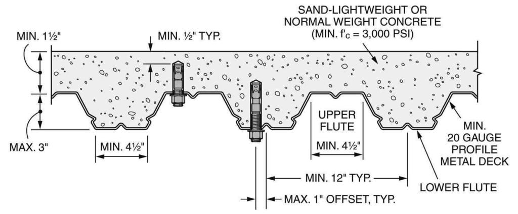
7 Anchoring and Fastening Systems for Concrete and Masonry Addendum Strong Bolt 2 Wedge Anchor Performance Data Strong-Bolt 2 Wedge Anchor Tension and Shear Strength Design Data for the Soffit of Concrete Over Profile Steel Deck, Floor and Roof Assemblies,2,6,9 Characteristic Symbol Units Nominal Anchor Diameter () Carbon Steel Stainless Steel Upper Lower Flute Upper Flute Lower Flute Flute * *See page for an explanation of the load table icons 2 2 Nominal Embedment Depth h nom Effective Embedment Depth h ef ft-lbf Installation Torque T inst (N-m) Pullout Strength, concrete on metal lb N deck (cracked),4 p,deck,cr (kn) Pullout Strength, concrete on metal lb N deck (uncracked),4 p,deck,uncr (kn) Steel Strength in Shear, concrete on lb V metal deck st.deck (kn) For SI: inch = 2.4 mm, lbf = 4.4 N. 2 () (4) 0 (40.7) (86) (76). The information presented in this table must be used in conjunction with the design criteria of ACI 8 Appendix D, except as modiied below. 2. Proile steel deck must comply with the coniguration in the igure below, and have a minimum base-steel thickness of 0.0 inch (0.889 mm) [20 gauge]. Steel must comply with ASTM A 6/A 6M SS Grade with minimum yield strength of 8,000 psi (262 Mpa). Concrete compressive strength shall be,000 psi minimum.. For anchors installed in the sofit of sand-lightweight or normal-weight concrete over metal deck loor and roof assemblies, calculation of the concrete breakout strength may be omitted. 4. In accordance with ACI 8 Section D...2, the nominal pullout strength in cracked concrete for anchors installed in the sofit of sand-lightweight or normal-weight concrete over metal deck loor and rood assemblies N p,deck,cr shall be substituted 2 4 (70) 2 4 (7) 60 (8.) 4 2 (4) 4 (02) (86) 2 4 (70) 90 (22.0) (4) (27) 2 () (4) 0 (40.7) 2 4 (70) 2 4 (7) 60 (8.) 2 () (4) 0 (40.7) (86) (76) for N p,cr. Where analysis indicates no cracking at service loads, the normal pullout strength in uncracked concrete N p,deck,uncr shall be substituted for N p,uncr.. In accordance with ACI 8 Section D.6..2(c), the shear strength for anchors installed in the sofit of sand-lightweight or normal-weight concrete over metal deck loor and rood assemblies V st,deck shall be substituted for V sa. 6. The minimum anchor spacing along the lute must be the greater of.0 hef or. times the lute width. 7. The characteristic pull-out strength for greater concrete compressive strengths shall be increased by multiplying the tabular value by (f' c /,000 psi) 0. or( f' c /20.7 MPa) The characteristic pull-out strength for greater concrete compressive strengths shall be increased by multiplying the tabular value by (f' c /,000 psi) 0. or (f' c / 20.7 MPa) Minimum distance to edge of panel is 2 hef. 2 () (4) 0 (40.7),20 7 (.6) 7 2,20 7 (9.9) 7 2,040 7 (9.) 7 2,70 7 (2.) 7 2,6 7 (.6) 7 4,990 7 (22.2) 7,60 7 (7.2) 7,78 7 (6.8) 7,20 8 (.0) 8 2,79 8 (2.4) 8,40 8 (6.) 8,76 7,0 7 2,80 7,840 7,68 7 6,6 7 2,27 7 4,79 7,80 8,90 8,990 8 (7.9) 7 (4.0) 7 (.) 7 (7.) 7 (6.4) 7 (29.2) 7 (0.) 7 (2.) 7 (7.0) 8 (7.6) 8 (8.9) 8,9 (7.),490 (.) 2, (9.) 4,80 (20.4) 2,640 (.7) 7,000 (.) 4,060 (8.),920 (26.) 2,28 (0.2),78 (6.8),80 (7.0) M 2" M 2" typ. M,000 psi normal or sand-lightweight concrete Max. " M 4 2" Upper flute M 4 2" M 2" typ. Max. " offset, typ. M 20 gauge steel deck Lower flute Example: Strong-Bolt 2 Wedge Anchor Allowable Stress Design Tension Values, 2,, 4,, 6, 7, 8, 9 for Illustrative Purposes Nominal Anchor Diameter () 2 Nominal Embedment Depth, h nom () Carbon Steel Effective Embedment Depth, h ef () Allowable Tension load, fn n /a (lbs.) 2, , ,8 7 2,0* 2 4 2, ,96 Stainless Steel 2, ,080 * *See page for an explanation of the load table icons Design Assumptions:. Single anchor. 2. Tension load only.. Concrete assumed to remain uncracked for the life of the anchorage. 4. Load combinations taken from ACI 8 Section 9.2 (no seismic loading).. 0% Dead Load (D) and 70% Live Load (L); Controlling load combination is.2d +.6L. Calculation of a based on weighted average: α =.2D +.6L =.2(0.) +.6(0.7) = Normal weight concrete with f' c = 2,00 psi. 7. c a = c a2 c ac 8. Concrete thickness, h h min 9. Values are for Condition B (supplementary reinforcement in accordance with ACI 8 D.4.4 is not provided.) *Illustrative Procedure (reference Strong-Bolt 2 Tension Strength Design Data Table): Strong-Bolt 2, 2"-diameter with an effective embedment depth, h ef = ". Step : Calculate steel strength in tension in accordance with ACI 8 D..; sa N sa = 0.7 x 2,00 = 9,07 lbs. Step 2: Calculate concrete breakout strength in tension in accordance with ACI 8 D..2; cb N cb = 0.6 x 7,440 = 4,86 lbs. Step : Calculate pullout strength in tension in accordance with ACI 8 D..; p N p, uncr = 0.6 x,2 =,46 lbs. Step 4: The controlling value from Steps, 2, and above in accordance with ACI 8 D.4..2; N n =,46 lbs. Step : Divide the controlling value by the conversion factor a as determined in footnote ; T allowable,asd = N n /α =,46 /.48 = 2,0 lbs. The edge distance, spacing and member thickness requirements in the Strong-Bolt 2 Installation Information Table apply to a single anchor and anchor groups. 2
.")


8 Strong-Bolt 2: The Next Generation of Wedge Anchors Anchor Selector Software ACI 8 Anchor Selector Software for ACI 8 Anchor Selector Software for ACI 8 analyzes and offers anchor solutions using the ACI 8, Appendix D strength design methodology (or CAN/CSA A2. Annex D limit states design methodology). It provides cracked- and uncracked-concrete anchor solutions for many Simpson Strong-Tie Anchor Systems mechanical and adhesive anchors. With its easy-to-use graphical interface, Anchor Selector Software for ACI 8 eliminates the need for tedious calculations by hand that would otherwise be necessary to determine cracked concrete anchor solutions. Features/Benefits Free download Quick and accurate analysis or design of anchor solutions results in increased productivity by eliminating the need to conduct time consuming calculations Graphical User Interface is intuitive and easy to use Includes prequalified post-installed mechanical and adhesive anchor solutions for cracked and/or uncracked concrete Includes a variety of concrete base material configurations Concrete Types Normal weight concrete Lightweight concrete Normal weight concrete over metal deck Sand-lightweight concrete over metal deck Includes cast-in-place anchor solutions Single and multiple anchor layouts provide solutions for multiple design applications Determines proper anchor solutions in situations where tension and shear forces will be acting simultaneously Capability to save input and results allows the designer to save data for later use. Additionally, input files can be easily modified to create new analysis/ design cases. Ability to save and print detailed calculations allows for verification of results Capability to resolve bi-axial bending moments imposed from attached member into anchor forces Auto update feature allows notification and download of the latest version of the software as updates become available To download this free software, go to This flier is effective until January, 202, and reflects information available as of October, 200. This information is updated periodically and should not be relied upon after January, 202; contact Simpson Strong-Tie for current information and limited warranty or see SimpSon Strong-tie Company inc. P.O. BOx 0789, PLEASANTON, CA 9488 F-SAS-STB20 0/0 ExP. /
9 Æ Æ Æ Æ Æ Æ Æ ICC-ES Evaluation Reports are not to be construed as representing aesthetics or any other attributes not specifically addressed, nor are they to be construed as an endorsement of the subject of the report or a recommendation for its use. There is no warranty by ICC Evaluation Service, LLC, express or implied, as to any finding or other matter in this report, or as to any product covered by the report.
10 φ φ φ φ Ψ Ψ, =,/,, =,/. Ψ φ l
11 Ψ, =,., =.0 λ, =, = φ φ α α
12 +,,.2
13 l β
14 φ ψ φ φ φ φ φ φ φ φ φ φ φ φ Ψ Ψ
15 φ l φ φ φ φ φ φ φ φ φ φ φ
16
17 Τ allowable α φ φ φ φ α φ α
18
19
20
21
22 Æ Æ Æ Æ Æ Æ
23
24