Vehicle Restraint Systems
|
|
|
- Stella Eugenia Nash
- 5 years ago
- Views:
Transcription

1 Vehicle Restraint Systems Herbert Nyamakope (TII) Eoin Doyle (Arup) TII Standards Training 2017 Athlone 09 th May 2017 Carrick on Shannon 11 th May 2017 Cork 16 th May 2017 Dublin 18 th May 2017
2 VRS Overview of Changes

3 VRS Need for Change 2012/2013 substantial inventory gathering of VRS on the national road network Myriad of issues identified

4 VRS Need for Change

5 VRS Need for Change
6 VRS Need for Change Consultants were tasked with designing VRS for locations identified DN-REQ compliant VRS could only be designed for 30% of the locations Remaining 70% would require a risk based approach to design solutions for VRS in constrained locations


7 VRS Need for Change Terminals and Transitions Issues with historical terminals Issues with transitions to bridge parapets Not CE Marked products as no harmonised European standards Assessment for compliance?

8 VRS Need for Change Existing standards DN-REQ VRS Design When, where, what safety barriers are required Hazards definitions Mitigation of hazards Risk assessments Terminals and Transitions Does not fully address: Designs in constrained locations e.g. no working width Connections to historical bridge parapets Other constraints associated with retrofitting to legacy roads

9 VRS Need for Change Existing standards CC-SPW Installation specification Written mainly for new installations on new road schemes Recent revisions to comply with CPR Does not fully cover: Maintenance/repair issues Ground condition testing Compliance with manufacturers installation manual


10 VRS - Need for Change Main problems: Inadequate designs Poor installations Limitations in standards Evident a lack of understanding of proper design and installation of VRS within industry How do we address these challenges?!
11 Problem Action Status Comment Design VRS Design Course Ongoing 2 Day VRS Design Course developed Candidates certified to date Design VRS in Constrained Locations Complete DN-REQ Retrofitting VRS on Single Carriageways issued as Interim Technical Advice for industry feedback Design Update to Standard In progress DN-REQ currently being updated for publication in Q3 (Safety barriers & parapets) Design Terminal and Transitions Complete DN-REQ and outlining the assessment procedure for terminals and transitions issued, compliant lists being developed Design National VRS Consultant In Progress Assist LAs in designing, tendering and supervising annual repair /replacement programs Construction Update to Specification In Progress CC-SPW currently being updated for publication in September Construction Framework for Installers In Progress Tenders currently being reviewed Strict conditions for qualification Maintenance Other Guidance for Repair and Maintenance Promote establishment of an industry led VRS association In Progress Complete Currently being finalised for review, publication date to be confirmed IBA established, engaging with TII re standards update and training
12 VRS Retrofitting VRS to the Single Carriageway National Road Network Eoin Doyle (Arup)

13 VRS Retrofit DN-REQ DN-REQ issued as Interim Technical Advice in February 2017 Applicable where site conditions and constraints are such that design compliance with DN-REQ Safety Barriers is not achievable
14 VRS Retrofit Design Process Does not provide specific design solutions for particular constraints Provides a risk based approach to designing at constrained locations Provides designers with a defined process to inform their design decisions Provides for a consultation and approval procedure with TII Includes examples of possible solutions with advantages, disadvantages and limitations of each to assist the designer in developing a solution


15 Categories of Constraints VRS at Constrained Locations; Lack of set back/working width; Installations within the clear zone; Accesses preventing full length of need; Third party considerations; Road junctions i.e. VRS continuing down the side road. VRS at structures; VRS within urban settings. Separate design process flowchart for each category
16 Overview of the Design Process Consult with TII to check if any improvement or refurbishment works are planned at the location Initial risk assessment to check if a VRS is actually required Assess if mitigation measures can be implemented to remove the need for a VRS Analyse the site specific constraints that may prohibit a compliant VRS design Develop suitable design options identifying the advantages and disadvantages of each. Identify the preferred option with appropriate reasoning, including consideration of whole life cycle costs, and Submit VRS PDR to TII for approval.
17 Category A Constrained Locations Consult with TII Network Management Are there any minor improvement, road safety or maintenance schemes planned for the location? Identify the hazard Steep side slopes; Water with a depth > 0.6m; Fixed objects within the clear zone; Linear Hazards. DN-REQ Chapter 8 Risk Assessment Regrade the side slopes; Remove the hazard from the clear zone; Install passively safe road furniture; Clearance of vegetation/trees; Use of delineation markings; Obtain additional lands. Lack of set back or working width; Installations within the clear zone; Third party considerations; Access preventing the full length of need; Road junctions i.e. existing VRS continuing down the side road. Is a VRS still required post risk assessment? Yes Can mitigation measures be implemented? (If Yes, calculate life cycle costs of mitigation measures) No Can the VRS be designed in accordance with DN-REQ ? No Identify the constraints preventing a compliant design Prepare a preliminary design report Submit the report through the TII departures website No Yes Consider VRS removal (If a VRS is to be removed, submit a completed DN-REQ Risk Assessment Sheet to TII) Consult DN-REQ for VRS design and specification Analyse the problem; List all possible design options; Include life cycle costing analysis; Identify the preferred option with reasoning.
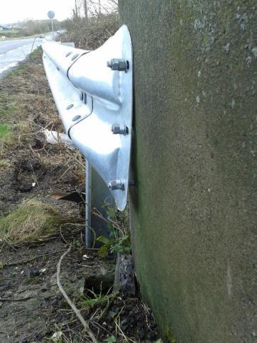
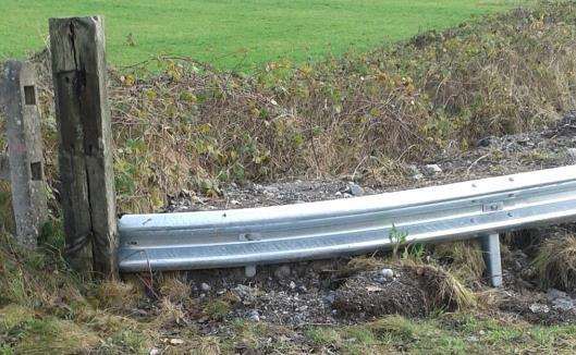
18 Constrained Location - Worked Example Consult with TII Network Management Identify the hazard Steep drop to the adjacent land. Stone wall within the clear zone.

")

19 Constrained Location - Worked Example DN-REQ Chapter 8 Risk Assessment Is a VRS still required post risk assessment? Yes Can mitigation measures be implemented? (If Yes, calculate life cycle costs of mitigation measures) Identify the constraints preventing a compliant design Lack of set back and working width requirements. No Can the VRS be designed in accordance with DN-REQ-03034? No

20 Constrained Location - Worked Example Prepare a preliminary design report Analyse the problem; List all possible design options; Install a high containment VRS; Install concrete baseplates; Install delineation; Bespoke option.


21 Constrained Location - Worked Example Identify the preferred option: Construct a dedicated pull in area; Construct a reinforced masonry clad concrete wall; Construct a high containment kerb; Install edge delineation markers; Renew road markings and install new signs. Reasoning: Mitigation is not practical It is an area of natural beauty which an aluminium VRS would detract from. Submit the report through the TII departures website


22 Category B - Structures Exposed parapet ends are a hazard Parapets have no/unknown containment; No transition between the safety barrier and the parapet

23 Rail Bridge Crossing - Constraints No transition included; An unapproved connection detail.


24 Culvert Crossings - Constraints No end terminal, no working width, length of need not catered for, height above the carriageway too low.
25 Category B Structures Consult with the TII Regional Bridge Manager Exposed parapet ends No transition between the safety barrier and the parapet Is the structure included in a capital refurbishment programme? Identify the hazard Can mitigation measures be implemented (If Yes, calculate life cycle costs of mitigation measures) No Taper bridge parapets away from the carriageway; Increase the length of a culvert so that the parapets are outside the clear zone. Masonry parapet with unknown containment; Pre IS EN 1317 parapet which may need to be replaced; Cultural heritage issues which may prohibit modification or demolition of an existing parapet; Access or junction adjacent to the structure. Insufficient lands available to provide the required approach and departure lengths; Analyse the problem; List all possible design options; Include life cycle costing analysis for each option; Identify the preferred option with reasoning. Can the VRS be designed in accordance with DN-STR-03011/ DN-REQ-03034? No Identify the constraints preventing a compliant design Propose options in consultation with the TII Regional Bridge Manager Prepare a preliminary design report Submit the report through the TII departures website Yes Consult DN-STR-03011/ DN-REQ for VRS design and specification Possible options Install barriers in front of parapet (check working width and setback); Full parapet reconstruction to include transition to safety barrier Modify parapets to enable VRS connection (all proposed transitions need approval); Crash Cushions; Other innovative alternatives.


; Full parapet")

26 Category B Structures Consult with the TII Regional Bridge Manager Identify the hazard Can mitigation measures be implemented (If Yes, calculate life cycle costs of mitigation measures) No Can the VRS be designed in accordance with DN-STR-03011/ DN-REQ-03034? No Identify the constraints preventing a compliant design Propose options in consultation with the TII Regional Bridge Manager Prepare a preliminary design report Submit the report through the TII departures website Yes Consult DN-STR-03011/ DN-REQ for VRS design and specification Possible options Install barriers in front of parapet (check working width and setback); Full parapet reconstruction to include transition to safety barrier Modify parapets to enable VRS connection (all proposed transitions need approval); Crash Cushions; Other innovative alternatives.
27 Category C - VRS within urban settings VRS should not be provided in urban settings unless exceptional circumstances Category C flowchart provides a risk based decision making process primarily for use when considering the removal of legacy VRS: in urban settings or speed limit zones; locations where the speed limit may have been reduced subsequent to the installation of the VRS; locations where traffic calming may have been reduced subsequent to the installation of the VRS.


28 VRS within urban settings
29 Category C Urban Settings Consult with TII Network Management Are there any minor improvement, road safety or maintenance schemes planned for the location? Risk Assessment Identify the hazard Are traffic calming measures in place? Have vehicle speeds been adequately reduced potentially allowing for VRS removal? Steep side slopes; Water with a depth > 0.6m; Fixed objects within the reduced clear zone; Linear Hazards. Speed limit reduced to 50 or 60 km/h; Segregated turning lanes; Reduced carriageway width; Gateway set up; Hatched central reserve; Reduced Clear Zone width. * * Playgrounds; Playing pitches; Schools; Monuments; ESB sub stations; Bridge with pedestrians. Domestic/commercial/agricultural accesses; Street furniture; Cultural heritage; Headstones; Town/village name installations; Pedestrian/cyclist facilities. * Yes Are there third party considerations? Yes Can mitigation measures be implemented (If Yes, calculate life cycle costs of mitigation measures) No Can the VRS be designed in accordance with DN-REQ-03034? No Identify the constraints preventing a compliant design No Yes Consider VRS removal (If a VRS is to be removed, submit a Risk Assessment to TII) Remove the hazard from the reduced clear zone for urban areas; Pipe and backfill drainage ditches; Build a wall in front of school/playground. Consult DN-REQ for VRS design and specification * Analyse the problem; List all possible design options; Include life cycle costing analysis; Identify the preferred option with reasoning. Prepare a VRS preliminary design report Submit the report through the TII departures website * Non-exhaustive list.
; MS Word templates available http://tiipublications.")
30 VRS Preliminary Design Report Templates for VRS PDR for each category of constraint are provided as appendices including worked examples; Simple format with standard information in line with design process required; Life cycle cost analysis required (SAVERS); MS Word templates available
31 VRS Terminal and Transition Assessment Procedures Eoin Doyle (Arup)

32 DN-REQ Terminal Assessment Procedure New Standard established to allow an assessment to be undertaken of the suitability of end terminals proposed for use with safety barriers on Irish national roads so as to develop a Compliant Terminals List Need for the Standard Safety barrier end terminals not currently CE marked products no Harmonised European Standard. DRAFT pren is being developed for the testing and approval of terminal systems. TII have implemented the testing requirements of pren in DN-REQ Safety Barriers. Standard will allow equivalent procedure to CE Marking based on Draft EN Standard. Some key items not clearly defined within pren and are open to interpretation clarified within standard. 32

33 DN-REQ Terminal Assessment Procedure Assessment Procedure Independent professional review of the test documentation provided by the supplier. Terminal Assessment Checklist of documentation to be provided included as appendix. Individual Terminal Test Assessment form used as a standard template of review and as a checklist for the minimum requirements of each individual impact test. Terminal Assessment Summary form will be used to summarise findings of the independent review for each impact test. Systems assessed as having undergone appropriate testing shall be added to the Compliant Terminal Systems list on the TII Publications website. 33


34 DN-REQ Terminal Assessment Procedure Items Clarified within Standard Critical Impact Point Test Approach 6 - pren 1317: The aim of this test is to evaluate the danger of pocketing where there is a sudden change in stiffness between the connecting barrier and the terminal. PrEN does not provide specific parameters in relation to choosing the CIP. 2m to 5m is provided as guidance within standard based on experience and pren 1317: If outside range requires computational simulations to verify point chosen is most critical point to assess potential pocketing. 34


35 DN-REQ Terminal Assessment Procedure Items Clarified within Standard Connecting to safety barriers systems other than that which the terminal was originally tested with Required to notify TII - may or may not require further submission depending on characteristics of connecting barrier Where connected directly to different barrier: the cross section and material of the proposed barrier compared to the barrier used for the ITT the difference in dynamic deflection between the barrier system used for the ITT and the proposed system; and an assessment of a simulated crash test using the proposed barrier if deemed necessary. Where terminal is provided with the transition piece it was tested with: connection to adjacent barrier is subject to transition requirements of ENV 1317:4. 35
36 DN-REQ Transition Assessment Procedure New Standard established to allow an assessment to be undertaken of the suitability of transitions between VRS of different performance or cross section proposed for use on Irish national roads so as to develop a Compliant Transitions List Need for the Standard Transitions not currently CE marked products no Harmonised European Standard. Standard will allow equivalent procedure to CE Marking based on Draft EN Standard through an independent assessment of test results. Some key items in relation to the testing of transitions are clarified within standard. 36


37 DN-REQ Transition Assessment Procedure Assessments Full Scale Physical Impact Tests Simulated Crash Tests 37
38 DN-REQ Transition Assessment Procedure Assessment Procedure Individual Transition Physical Test Assessment Form used to assess each individual physical impact test. The virtual tests will be assessed and a Virtual Test Assessment Report will be prepared to summarise the findings of the assessment. Transitions deemed suitable following assessment under this Standard will be added to a Compliant Transitions list on the TII Publications website 38


39 DN-REQ Transition Assessment Procedure Items Clarified within Standard The point shall be taken as the point of intersection of a straight line parallel to the vehicle centreline, at the maximum width of the vehicle. Light Vehicle Test (TB11) to evaluate the impact severity of the transition. Containment Test (TB32 or higher) to evaluate the containment level of the transition and to identify any potential for pocketing 39
40 Questions & Answers Thank you