Construction Entrance / Construction Road Stabilization Alturnamats & Versamats Dewatering Dandy Dewatering Bag / Dirt Bag...
|
|
|
- Ross Booth
- 5 years ago
- Views:
Transcription
1 CONTENTS Construction Entrance / Construction Road Stabilization... 1 Alturnamats & Versamats... 1 Dewatering... 8 Dandy Dewatering Bag / Dirt Bag... 8 Diversion Dike Diversion Dike of Compacted 21A or #26 Stone Inlet Protection Dandy Bag / Dandy Curb / Dandy Curb Bag / Dandy Curb Sack / Dandy Sack Erosion Eel / Gutter Buddy / Gutter Gator Grate Pyramid SiltSack Outlet Protection or Ditch Dissipation Alternatives Shoremax Flexible Transition Mat Perimeter Control Erosion Eel Slope Interruption Device (SID) Terra Tube - Fiber Filtration Tube (FFT) Non-VESCH and proprietary control measures shall be installed per the manufacturer s instructions and with the intent of the VESCH specifications. Should non-vesch control measures fail to effectively control soil erosion, sediment deposition, and non-agricultural runoff, then VESCH control measures shall be utilized. Please note that all Non-VESCH measures will require that a detail, narrative, and manufacturer s installation and maintenance requirements be shown on the approved plan and/or included in the SWPPP. Appendix F: Non-VESCH Specifications Page i

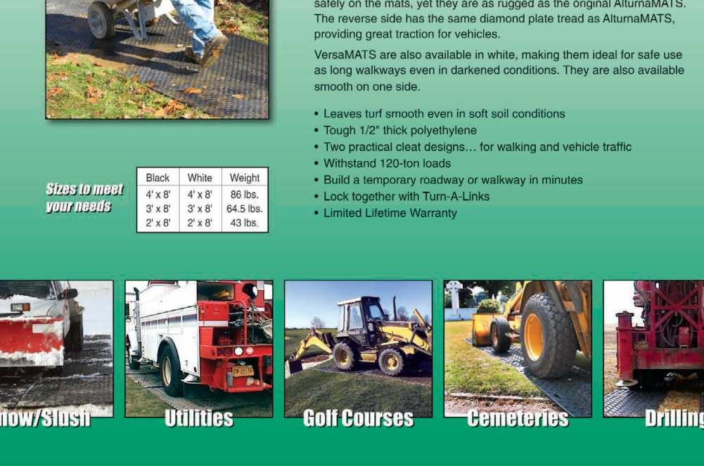
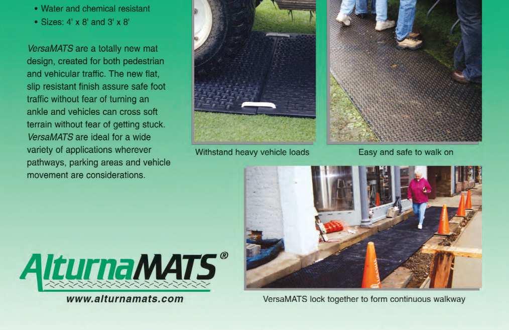
2 CONSTRUCTION ENTRANCE / CONSTRUCTION ROAD STABILIZATION ALTURNAMATS & VERSAMATS Definition Temporary protective mats placed at points of ingress and egress or for access to other construction activities on-site. Purpose To protect existing ground cover from damage and provide tracking for vehicular access. Conditions Where Practice Applies Wherever traffic will be entering or leaving a construction site, particularly for areas that only need access for a short amount of time (2 weeks or less) when installing a construction entrance or construction road stabilization is not practicable. Planning Considerations Minimum Standard #17 requires that provisions be made to minimize the transport of sediment by vehicular traffic onto a public or paved surface. Providing matting to prevent tires from coming into contact with grassed or denuded areas will minimize possible tracking and assist in keeping existing vegetation in good condition.. This measure is not acceptable where vehicular traffic will be driving off of matting onto denuded areas, but may be used to connect to existing construction entrances or construction road stabilization. Appendix F: Non-VESCH Specifications Page 1


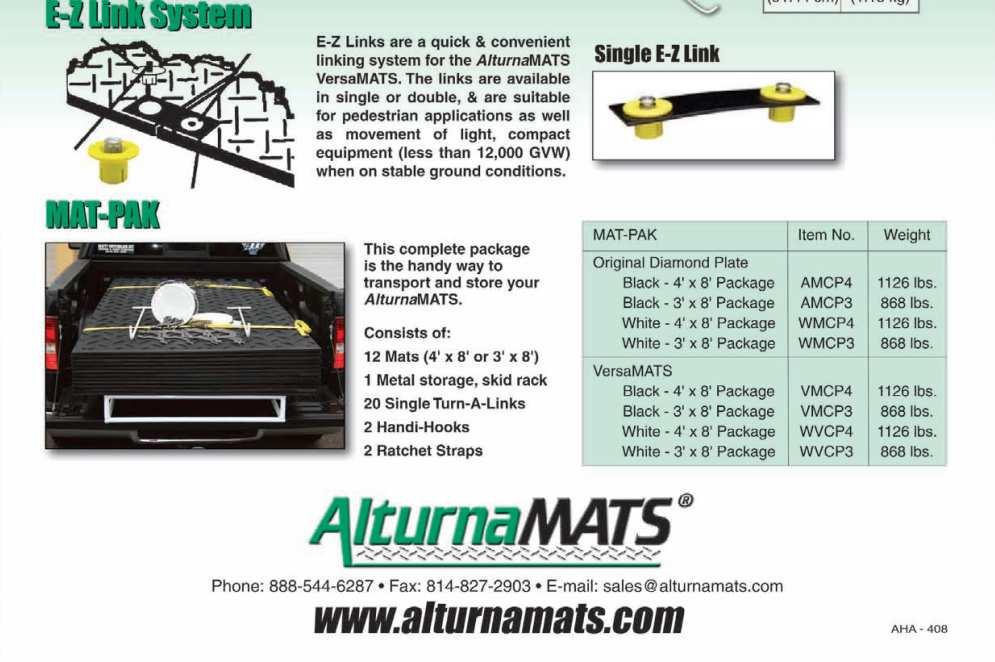
3 Construction Specifications 1. Lay down mats where vehicle/equipment tires/tracks may come into contact with the ground. 2. To keep mats joined together, links may be installed. Appendix F: Non-VESCH Specifications Page 2

4 Appendix F: Non-VESCH Specifications Page 3

5 Appendix F: Non-VESCH Specifications Page 4

6 Appendix F: Non-VESCH Specifications Page 5

7 Appendix F: Non-VESCH Specifications Page 6


8 Maintenance/Inspections The matting and access way shall be maintained in a condition which will prevent tracking or flow of mud onto public rightsof-way and paved surfaces. All materials spilled, dropped, or washed from vehicles onto roadways or into storm drains must be removed immediately. Where sediment is transported onto a paved or public road surface, the road surface shall be cleaned thoroughly at the end of the day as required my minimum standard #17. If matting becomes separated from adjacent pieces, links will need to be installed to keep mats aligned as needed. Appendix F: Non-VESCH Specifications Page 7


9 DEWATERING DANDY DEWATERING BAG / DIRT BAG Definition A temporary settling and filtering device for water which is discharged from dewatering activities. Purpose To filter sediment-laden water prior to the water being discharged from the site. Conditions Where Practice Applies Wherever sediment-laden water must be removed from a construction site by means of pumping. Planning Considerations Minimum Standard #19 requires that properties and waterways downstream be protected from sediment deposition. Water which is pumped from a construction site usually contains a large amount of sediment. A dewatering structure is designed to remove the sediment before water is released off-site. Appendix F: Non-VESCH Specifications Page 8
10 A dewatering structure may not be needed if there is a well stabilized, vegetated area on-site to which water may be discharged. The area must be stabilized so that it can filter sediment and at the same time withstand the velocity of the discharged water without eroding. A minimum filtering length of 75 feet must be available in order for such a method to be feasible. Design Criteria 1. The Dewatering Bag used for each project must be sized appropriately for the pump used. DO NOT allow a pump to be used that discharges greater than the allowable rate allowed for the Dewatering Bag to be used. Construction Specifications 1. Lifting straps (not included) should be placed under the unit to facilitate removal after use. 2. Unfold Dewatering Bag on a stabilized area over dense vegetation, straw, or gravel (if an increased drainage area is needed) or as detailed in plans. 3. Insert discharge hose from pump into Bag a minimum of six (6) inches and tightly secure with attached strap to prevent water from flowing out of the unit without being filtered. 4. Must be monitored during use. Maintenance/Inspections 1. Ensure water is not discharging from the hose connection point. Stop pumping and re-secure if needed. 2. Replace the unit when ½ full of sediment or when sediment has reduced the flow rate of the pump discharge to an impractical rate. Appendix F: Non-VESCH Specifications Page 9


 where an earthen diversion dike is not practical to protect disturbed areas and slopes or retain sediment")
11 DIVERSION DIKE DIVERSION DIKE OF COMPACTED 21A OR #26 STONE Definition A temporary ridge of compacted stone constructed at the top or base of a sloped area of a proposed construction site. Purpose 1. To divert stormwater runoff from upslope drainage areas away from construction activity. 2. To divert sediment-laden runoff from a disturbed area to a sediment-trapping facility such as a sediment trap or sediment basin. Conditions Where Practice Applies Wherever stormwater runoff must be temporarily diverted on an impervious surface (pavement, concrete, compacted gravel, etc.) where an earthen diversion dike is not practical to protect disturbed areas and slopes or retain sediment on site during construction. These structures generally have a life expectancy of 18 months or less, which can be prolonged with proper maintenance. Appendix F: Non-VESCH Specifications Page 10
12 Planning Considerations A temporary diversion dike of compacted 21A or #26 stone is intended to divert overland sheet flow to a stabilized outlet or a sediment-trapping facility. When used at the up-slope from construction activity, the structure prevents additional stormwater runoff from flowing through the construction site and the potential of greater erosion and sediment transportation. When used down-slope from construction activity, the structure protects adjacent and downstream areas by diverting sediment-laden runoff to a sediment trapping facility. The dike itself must be adequately compacted to prevent erosion of the dike itself. The dike must have a positive grade to assure drainage, but if the gradient is too great, precautions must be taken to prevent erosion due to high velocity channel flow behind the dike. The cross-section of the channel which runs behind the dike should be of a parabolic or trapezoidal shape to help inhibit a high velocity of flow which could arise in a vee ditch. Design Criteria Drainage Area - The maximum allowable drainage area is 5 acres. Height The minimum allowable height measured from the upslope side of the dike is 18 inches. Side Slopes 1 ½:1 or flatter, along with a minimum base width of 4.5 feet. Grade The channel behind the dike shall have a positive grade to a stabilized outlet. Construction Specifications 1. Temporary diversion dikes of compacted 21A or #26 stone must be installed as a first step in the land-disturbing activity and must be functional prior to upslope land disturbance. 2. The dike shall be adequately compacted to prevent failure. 3. The dike should be located to minimize damages by construction operations and traffic. Maintenance The measure shall be inspected after every storm and repairs made to the dike, flow channel, outlet or sediment trapping facility as necessary. Once every two weeks, whether a storm event has occurred or not, the measure shall be inspected and repairs made as needed. Damages caused by construction traffic or other activity must be repaired before the end of the working day. Appendix F: Non-VESCH Specifications Page 11
13 INLET PROTECTION DANDY BAG / DANDY CURB / DANDY CURB BAG / DANDY CURB SACK / DANDY SACK Definition A temporary filter for a storm drain inlet or curb inlet. Purpose To prevent sediment from entering storm drainage systems prior to permanent stabilization of the disturbed area. Conditions Where Practice Applies Where existing or proposed grated storm drain inlets are to be made operational before project completion and permanent stabilization of the corresponding disturbed drainage area. Planning Considerations Minimum Standard #10 requires that all storm drain inlets that are made operational during construction shall be protected so that sediment-laden water cannot enter the conveyance system without first being filtered or otherwise treated to remove sediment. This practice contains several types of inlet filters which have different applications dependent upon site conditions and the type of inlet. The following inlet protection devices are for drainage areas of one acre or less. Runoff from larger disturbed areas should be routed to a temporary sediment trap (VESCH Std. & Spec. 3.13) or a temporary sediment basin (VESCH Std. & Spec. 3.14). Design Criteria 1. The drainage area shall be no greater than 1 acre. 2. Dandy Bags, Curb Bags, and Curb Sacks are to be sized/ordered to fit the appropriately sized grate. (ie. A 3 x3 bag should not be used for a 2 x2 grate.) Construction Specifications Dandy Bag 1. Place the empty Dandy Bag over the grate as the grate stands on end. 2. Tuck the enclosure flap inside to completely enclose the grate. 3. Holding the lifting devises, insert the grate into the inlet being careful not to damage the Dandy Bag unit. Appendix F: Non-VESCH Specifications Page 12
14 Dandy Curb 1. Place Dandy Curb inlet protection unit on ground with aggregate pouch on street side near inlet it will be installed on. 2. Fill pouch with aggregate such as #5-7, 8 s or similar to a level (at least ½ full) that will keep unit in place during a rain event and create a seal between the Dandy Curb and the surface of the Street. Reseal Velcro access. 3. Center the unit against curb or median inlet opening so that the curb side of the unit creates a seal with the curb or median barrier and inlet structure. There will be approximately twelve (12) inches of the inlet protection unit overhanging on each side of the opening. If the unit is not installed in this manner, it will not function properly. Dandy Curb Bag 1. Place the empty Dandy Curb Bag unit over the grate as the grate stands on end. 2. Tuck the enclosure flap inside to completely enclose the grate. 3. Holding the lifting devices, being careful not to damage the sewn fabric unit, insert the grate into its frame, street side edge first, then lower back edge with cylindrical tube into place. The cylindrical tube should be partially blocking the curb hold opening when installed properly. Appendix F: Non-VESCH Specifications Page 13
15 Dandy Curb Sack 1. Remove the grate from the catch basin. 2. Stand the grate on end. Move the top lifting straps out of the way and place the grate into the Dandy Curb Sack unit so that the grate is below the top straps and above the lower straps. The grate should be cradled between the upper and lower straps. 3. Holding the lifting devices, insert the grate into the inlet, then lower back edge with cylindrical tube into place, being careful that the grate remains in place and being careful not to damage the Dandy Curb Sack unit. The cylindrical tube should partially block the curb hood opening when installed properly. Dandy Sack 1. Remove the grate from the catch basin. 2. Stand the grate on end. Move the top lifting straps out of the way and place the grate into the Dandy Sack unit so that the grate is below the top straps and above the lower straps. The grate should be cradled between the upper and lower straps. 3. Holding the lifting devices, insert the grate into the inlet, being careful that the grate remains in place and being careful not to damage the Dandy Sack unit. Maintenance/Inspections 1. Dandy products shall be inspected immediately after each measurable storm event (0.25 of rain or greater over a 24 hour period). 2. Accumulated sediment and debris from surface and vicinity of unit shall be removed. 3. If any rips/tears are noticed, unit will need to be replaced. Appendix F: Non-VESCH Specifications Page 14
16 EROSION EEL / GUTTER BUDDY / GUTTER GATOR Definition A temporary sediment filter for a storm drain curb inlet. Purpose To prevent sediment from entering storm drainage systems prior to permanent stabilization of the disturbed area. Conditions Where Practice Applies Where existing or proposed storm drain curb inlets are to be made operational before project completion and permanent stabilization of the corresponding disturbed drainage area. Planning Considerations Minimum Standard #10 requires that all storm drain inlets that are made operational during construction shall be protected so that sediment-laden water cannot enter the conveyance system without first being filtered or otherwise treated to remove sediment. This practice contains several types of filters by different manufacturers. The following inlet protection devices are for drainage areas of one acre or less. Runoff from larger disturbed areas should be routed to a temporary sediment trap (VESCH Std. & Spec. 3.13) or a temporary sediment basin (VESCH Std. & Spec. 3.14). Design Criteria The drainage area shall be no greater than 1 acre. Construction Specifications Erosion Eel 1. Center Erosion Eel at curb inlet. Install Flocmat cradle under Erosion Eel. 2. Ensure Erosion Eel does not completely cover inlet. Pull out from center to allow overflow as needed. 3. Tightly compress eel against curb on each end of inlet. There should be a minimum 2 run-out against curb on both sides. Appendix F: Non-VESCH Specifications Page 15
17 Gutter Buddy 1. Install the Gutterbuddy in front of the curb inlet opening. Each end of the Gutterbuddy should overlap the curb inlet a minimum of approximately 12. Appendix F: Non-VESCH Specifications Page 16

18 Gutter Gator Appendix F: Non-VESCH Specifications Page 17

. 2.")
19 Maintenance/Inspections 1. Inlet protection shall be inspected immediately after each measurable storm event (0.25 of rain or greater over a 24 hour period). 2. Accumulated sediment and debris from surface and vicinity of unit shall be removed to prevent ponding. 3. If any rips/tears are noticed, unit will need to be replaced. Appendix F: Non-VESCH Specifications Page 18


20 GRATE PYRAMID Definition A temporary filter for a grated storm drain inlet. Purpose To prevent sediment from entering storm drainage systems prior to permanent stabilization of the disturbed area. Conditions Where Practice Applies Where existing or proposed grated storm drain inlets are to be made operational before project completion and permanent stabilization of the corresponding disturbed drainage area. Planning Considerations Minimum Standard #10 requires that all storm drain inlets that are made operational during construction shall be protected so that sediment-laden water cannot enter the conveyance system without first being filtered or otherwise treated to remove sediment. This practice contains several types of inlet filters which have different applications dependent upon site conditions and the type of inlet. The following inlet protection devices are for drainage areas of one acre or less. Runoff from larger disturbed Appendix F: Non-VESCH Specifications Page 19

21 areas should be routed to a temporary sediment trap (VESCH Std. & Spec. 3.13) or a temporary sediment basin (VESCH Std. & Spec. 3.14). Design Criteria 1. The drainage area shall be no greater than 1 acre. Construction Specifications 1. Install Grate Pyramid base over grate. 2. Install anchors. 3. Install base with 2 to 4 anchors, as needed. 4. Install safety caps on anchors. 5. Install tower frame. 6. Push button to lock tower into base. 7. Slide tower filter over frame. 8. Tightly secure base to tower. Appendix F: Non-VESCH Specifications Page 20
. 2. Accumulated sediment and debris from surface and vicinity of unit shall be removed to prevent ponding. 3. If any rips/tears are noticed, unit will need to be replaced.")
22 Maintenance/Inspections 1. Inlet protection shall be inspected immediately after each measurable storm event (0.25 of rain or greater over a 24 hour period). 2. Accumulated sediment and debris from surface and vicinity of unit shall be removed to prevent ponding. 3. If any rips/tears are noticed, unit will need to be replaced. Appendix F: Non-VESCH Specifications Page 21


23 SILTSACK Definition A temporary filter for a grated storm drain inlet. Purpose To prevent sediment from entering storm drainage systems prior to permanent stabilization of the disturbed area. Conditions Where Practice Applies Where existing or proposed grated storm drain inlets are to be made operational before project completion and permanent stabilization of the corresponding disturbed drainage area. Planning Considerations Minimum Standard #10 requires that all storm drain inlets that are made operational during construction shall be protected so that sediment-laden water cannot enter the conveyance system without first being filtered or otherwise treated to remove sediment. This practice contains several types of inlet filters which have different applications dependent upon site conditions and the type of inlet. The following inlet protection devices are for drainage areas of one acre or less. Runoff from larger disturbed areas should be routed to a temporary sediment trap (VESCH Std. & Spec. 3.13) or a temporary sediment basin (VESCH Std. & Spec. 3.14). Design Criteria 1. The drainage area shall be no greater than 1 acre. Appendix F: Non-VESCH Specifications Page 22
24 Construction Specifications 1. Remove the grate and place the sack in the opening. Hold approximately six inches of the sack outside the frame. This is the area of the lifting straps. 2. Replace the grate to hold the sack in place. Maintenance/Inspections 1. Inlet protection shall be inspected immediately after each measurable storm event (0.25 of rain or greater over a 24 hour period). 2. Check for tears/rips in sack. If noticed, have replaced immediately. 3. The SiltSack is full and should be emptied when the restraint cord is no longer visible. a. To remove, take two pieces of 1 diameter rebar and place through the lifting loops on each side of the sack to facilitate the lifting of the SiltSack. Appendix F: Non-VESCH Specifications Page 23

25 OUTLET PROTECTION OR DITCH DISSIPATION ALTERNATIVES SHOREMAX FLEXIBLE TRANSITION MAT Definition A permanent, erosion-resistant ground cover. Purpose 1. To protect the soil from the erosive forces of concentrated runoff. 2. To slow the velocity of concentrated runoff while enhancing the potential for infiltration. 3. To stabilize slopes with seepage problems and/or non-cohesive soils. Conditions Where Practice Applies Wherever soil and water interface and the soil conditions, water turbulence and velocity, expected vegetative cover, etc., or such that the soil may erode under the design flow conditions. Adequate matting solutions may be used, as appropriate, at storm drain outlets, on channel banks and/or bottoms, roadside ditches, drop structures, at the toe of slopes, as a transition from impervious channels to vegetated channels, etc. Planning Considerations Minimum Standard # 11 requires that before newly constructed stormwater conveyance channels or pipes are made operational, adequate outlet protection and any required temporary or permanent channel lining shall be installed in both the conveyance channel and receiving channel. Appendix F: Non-VESCH Specifications Page 24

26 Design Criteria Appendix F: Non-VESCH Specifications Page 25

27 Construction Specifications Appendix F: Non-VESCH Specifications Page 26

28 Appendix F: Non-VESCH Specifications Page 27

29 Appendix F: Non-VESCH Specifications Page 28

30 Appendix F: Non-VESCH Specifications Page 29


31 PERIMETER CONTROL EROSION EEL Definition A temporary sediment barrier for perimeter control. Purpose 1. To intercept and detain small amounts of sediment from disturbed areas during construction operations in order to prevent sediment from leaving the site. 2. To decrease the velocity of sheet flows and low-to-moderate level channel flows. Conditions Where Practice Applies 1. Below disturbed areas where erosion could occur in the form of sheet or rill erosion and the installation of silt fence is not practicable such as on paved, concrete or other similar surfaces. Planning Considerations 1. Erosion Eels can be placed at the top, on the face, or at the toe of slopes to intercept runoff, reduce flow velocity, releasing the runoff as sheet flow, and provide reduction/removal of suspended solids from the runoff. 2. No trenching is required for the installation of Erosion Eels. Appendix F: Non-VESCH Specifications Page 30
.")
32 Design Criteria 1. Where the size of the drainage area is no more than one quarter acre per 100 feet of Erosion Eels. 2. See spacing recommendations chart for slope percentages. Construction Specifications 1. Prepare bed for Eel installation by removing any large debris including rocks, soil clods, and woody vegetation (greater than 1 inch in size). Erosion eels can also be placed over paved surfaces including concrete and asphalt with no surface preparation required. 2. Rake bed area with a hand rake or by drag harrow. 3. All surfaces shall be uniformly and well-compacted for maximum seating and stability of the Eels in place. 4. Bed the Eels in a FlocMat (coir matting) cradle per the detailed drawings. (Detail E1-G) 5. As Eels are placed in a row, butt ends of Eels together tightly by firmly pressing the tied end of the Eel against the sewn edge of the adjacent Eel. (Detail E1-B1) Appendix F: Non-VESCH Specifications Page 31

33 Appendix F: Non-VESCH Specifications Page 32
34 Appendix F: Non-VESCH Specifications Page 33
35 Appendix F: Non-VESCH Specifications Page 34
36 Maintenance/Inspections 1. Inlet protection shall be inspected immediately after each measurable storm event (0.25 of rain or greater over a 24 hour period). Any required repairs shall be made immediately. 2. Sediment deposits should be removed after each storm event. They must be removed when deposits reach approximately one-half the height of the Eel. 3. If any rips/tears are noticed, section of Erosion Eel will need to be replaced. Appendix F: Non-VESCH Specifications Page 35
37 SLOPE INTERRUPTION DEVICE (SID) TERRA TUBE - FIBER FILTRATION TUBE (FFT) Definition A fiber filter tube (FFT) of engineered composites used for sediment filtration and slope interruption. Purpose To provide filtration and slow down velocity of run-off on slopes. Conditions Where Practice Applies On slopes where the combination of slope gradient and slope length would create a critical erosion hazard. Slope Gradient Slope Length 0-7% 300 feet (100 meters) 7-15% 150 feet (50 meters) 15% & over 75 feet (25 meters) Planning Considerations Minimum Standard #7 requires that cut and fill slopes be designed and constructed in a manner that will minimize erosion. Installation of slope interruption devices assist in preventing slopes from becoming a critical erosion hazard. Appendix F: Non-VESCH Specifications Page 36

38 Construction Specifications Maintenance/Inspections 1. Tubes shall be inspected immediately after each measurable storm event (0.25 of rain or greater over a 24 hour period). Any required repairs shall be made immediately. 2. During inspections, if rill erosion is noticed, measures will need to be taken as soon as practical to re-grade and stabilize problem areas. Appendix F: Non-VESCH Specifications Page 37