Geosynthetics and Reinforced Soil Structures
|
|
|
- Aileen Craig
- 5 years ago
- Views:
Transcription
1 Geosynthetics and Reinforced Soil Structures Testing Requirements for Design of Reinforced Soil Walls Prof K. Rajagopal Department of Civil Engineering g IIT Madras, Chennai gopalkr@iitm.ac.inac in
2 Tests Required for the Design of Reinforced Soil Retaining i Walls Properties of soil Properties of reinforcement Soil-reinforcement interaction factors Reinforcement-facingfacing connection Reinforced Soil Walls - 6 2/59
3 SHEAR STRENGTH PROPERTIES OF SOIL C=0 (cohesive strength is neglected) Friction angle determined from small or large-box shear tests (stress state in direct shear box similar to that behind retaining wall) Range of normal pressures in the tests t should correspond to those expected in reinforced soil fill Peak friction angle is used for designs Reinforced Soil Walls - 6 3/59
4 Longterm Allowable Design Strength T LTDS FC CRF FD T FB ult FS T ult from index tension tests (ASTM D6637 or ASTM D4595) FC is the environmental degradation factor FB is the biological degradation factor FD is the construction induced damage (depends on method of compaction, size of aggregate etc.) FS is overall factor of safety CRF = creep reduction factor (depends on type of polymer, duration of service life, temperature, etc.) Reinforced Soil Walls - 6 4/59
5 Immersion of geosynthetic samples in a chemical environment to study the chemical/environmental degradation factor Source: IGS Reinforced Soil Walls - 6 5/59
6 Reference Geosynthetic Tensile Tests Reinforced Soil Walls - 6 6/59


7 Courtesy: Prof R.J. Bathurst, Royal Military College of Canada Reinforced Soil Walls - 6 7/59

8 Wide width strip tensile test results D Specimen gauge length = 200 mm T ult = ultimate tensile strength Rate of displacement equivalent to 10% strain/min Courtesy: Prof R.J. Bathurst, Royal Military College of Canada Reinforced Soil Walls - 6 8/59
9 Long Term Design Strength FS = 1.25 to 1.5 (typical) To take care of uncertainties in quality of the material and manufacturing defects, etc. Reinforced Soil Walls - 6 9/59
10 Default Values for Partial Factors of Safety Guidelines for Design, Specification, and Contracting of Geosynthetic Mechanically Stabilized Earth Slopes on Firm Foundations, Berg 1993 installation damage 3.0 creep 5.0 chemical degradation 2.0 biological damage 1.3 joint/seam 2.0 partial factor Reinforced Soil Walls /59
11 T a T ult Reinforced Soil Walls /59


12 Determination of partial factor for creep FS CR = ratio of T ult to creep limiting strength Constant load creep testing Reinforced Soil Walls /59
13 Reinforced Soil Walls /59
14 Determination of FS CR Example from in isolation creep rupture of a woven polyester geogrid 5000 T ult y = 93.18Ln(x) lo oad (lb/ft) y = Ln(x) FS CR = T ult T 75 years T 75 years 500 FS CR = elapsed dti time (hrs) Reinforced Soil Walls years Courtesy: Prof R.J. Bathurst, Royal Military College of Canada 14/59
15 CREEP CURVES SS20 : 5 bars x 6 ribs 8.1 kn/m 0.80 str rain (%) 0.60 experiment predicted (TRF) kn/m 4.3 kn/m 0.00 Creep testing of geosynthetics time (hours) Typical creep test data of geosynthetics
16 0 Strain% /mm) Strain rate(%strain/ (kn/m) T index = 80 kn/m -8 Sherby-Dorn plot between strain rate and strain Reinforced Soil Walls /59
17 Standard Test Method for Accelerated Tensile Creep and Creep-Rupture of Geosynthetic Materials Based on Time- Temperature Superposition Using the Stepped Isothermal Method Reinforced Soil Walls /59


18 Reinforced Soil Walls /59
19 TU-40 geogrid at 68% load level in SIM test strain (%) time (seconds) room temperature Temp = 45 deg. Temp = 59 deg. Temp = 73 deg. Temp = 87 deg. Temp = 95 deg. Reinforced Soil Walls /59
20 Installation damage ASTM D , ASTM and Federal Highway Administration guidelines (Publication No. FHWA NHI dated March 2001). Reinforced Soil Walls /59


 Placesteel")


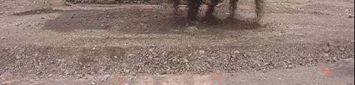
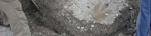
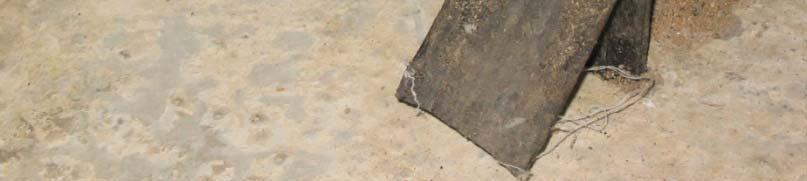
21 Project specific aggregate Passing % Particle Size (mm) Placesteel plates Place aggregate base layer Place geosynthetic samples Reinforced Soil Walls 6 21


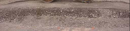

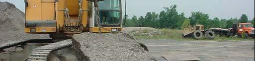
22 Placecover cover aggregate Compact aggregate using projectspecificcompaction compaction equipment Exhume samples Reinforced Soil Walls 6 22
23 Publication No. FHWA NHI A total of 6 control (virgin) specimens are tested (e.g ASTM ). A minimum of 9 exhumed specimens are required to be tested. A maximum of 18 tests is required if the coefficient of variation from the first 9 tests is greater than 5%. Reinforced Soil Walls /59
 (kn/m) 1 19752 109.77 2 20884 116.0 3 18839 104.")

 (kn/m) 1 17813 99.0 2 17776 98.")


24 CONTROL: Specimen Peak Load Peak Load No. (N) (kn/m) Mean Std. Dev. 773 Coef. of Var EXHUMED: <150 mm crushed stone Specimen Peak Load Peak Load No. (N) (kn/m) Mean Std. Dev. 750 Coef. of Var RF ID = 109.0/98.4 = 1.11 Courtesy: Prof R.J.Bathurst,RMC RMC Reinforced Soil Walls /59
25 Courtesy: Prof R.J. Bathurst, RMC Reinforced Soil Walls /59
26 Standard Test Method for Determining Connection Strength Between Geosynthetic Reinforcement and Segmental Concrete Units (Modular Concrete Blocks) Reinforced Soil Walls /59
27 loading frame hydraulic jack to apply vertical load on bricks blocks load cell geogrid jack to pull geogrid a. sectional view of apparatus
28 load cell roller grip b. plan view


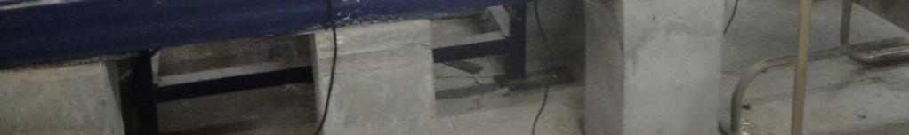
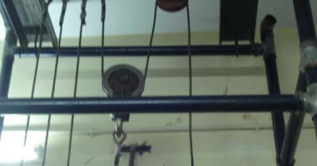
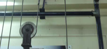
29 Laboratory test t facility for pullout/connection ti tests t Reinforced Soil Walls /59


30 Connection test between modular blocks and a uniaxial geogrid Openings filled with stone aggregate drainage blanket Reinforced Soil Walls /59
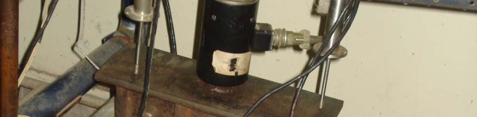
31 Close-up of the test arrangement for connection strength tests LVDT in the picture Reinforced Soil Walls /59
32 Connection loads at serviceability limit of 20 mm pullout load (k kn/m) normal load (kn/m) GX-40 GX-80 GX-100 GX-130 Reinforced Soil Walls /59
33 Ultimate limit state connection load capacity lout load (kn/ /m) pul normal load (kn/m) GX-40 GX-80 GX-100 GX-130 Reinforced Soil Walls /59


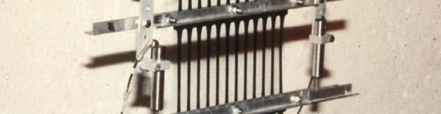
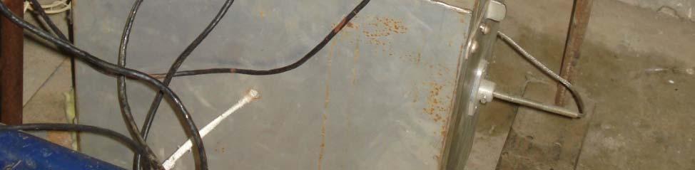
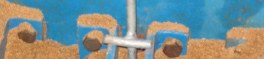
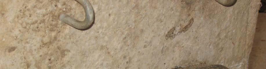
34 Connection strength test between geogrid and facing panel through positive connection 8 mm HYSD hooks and 16 mm diameter HYSD cross-bar Reinforced Soil Walls /59
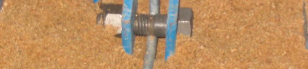
35 Arrangement at the front end with load cell and roller connection Reinforced Soil Walls /59
36 geogrid Normal pressure sand fill facing panel loop connector rod Schematic of the connection capacity test rigid connection at both ends Reinforced Soil Walls /59
37 geogrid Normal pressurep sand fill facing panel loop connector rod Schematic of test set up to determine the strength due to overlap Reinforced Soil Walls /59
38 Data from connection tests on a geogrid with T index =60 kn/m Sl. No. Normal pressure Connection type Maximum connection capacity & mode of failure (kn/m) kpa Frictional with lap length of 1.3m 20.6 (pullout/partial rupture) kpa Frictional with lap length of 1.3m 31 (pullout/partial rupture) 3 75 kpa Frictional with lap length of 1.3m 54 kn/m (rupture) 4 75 kpa Clamped connection at both ends 55 kn/m (rupture) Reinforced Soil Walls /59
39 Connection tests on geogrid with T index =350 kn/m Sl. No. Normal Connection type Maximum connection pressure capacity & mode of failure (kn/m) kpa Frictional connection (300 mm wide kn/m sample, m lap length) (pullout/partial ti l rupture) 2 75 kpa Frictional connection (300 mm wide kn/m sample, 1.3 m lap length) (pullout/partial rupture) 3 75 kpa Both ends clamped (300 mm wide 322 kn/m (rupture) sample) l) kpa Clamped at both ends (300 mm wide 325 kn/m (rupture) sample) Reinforced Soil Walls /59
40 Standard Test Method for Measuring Geosynthetic Pullout Resistance in Soil Minimum embedment length of sample = 610 mm Minimum Length/width ratio = 2 Minimum depth of soil above and below the reinforcement = 150 mm Rate of pullout displacement = 1 mm per minute Reinforced Soil Walls /59
41 Reinforced Soil Walls /59
42 Interpretation of data from pullout tests on geogrids resistance forces P P 2 L B tan v e L e =anchorage length=1.5 m Sl. Vertical Peak Interface =tan /tan No. pressure pullout friction (kpa) load (kn) angle kpa > kpa 39.7 kpa 75.9 kpa Reinforced Soil Walls /59
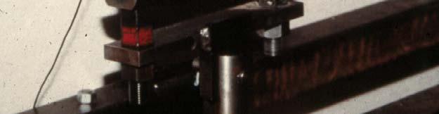
43 Testing of Vertical Plate Anchors Materials Anchor Reinforcements Strip Angles Bolts Side View Plan Anchor Strip Size (mm) Angle Size (mm) Type Type I Type II 40 (width) x 5 (thick) and 1500 (length) 70 (width) x 5 (thick) and 1500 (length) 50 x 50 x 5 (thick) and 150 (length) 130 x 130 x 12 (thick) and 350 (length)
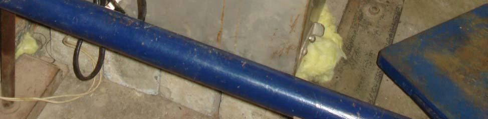
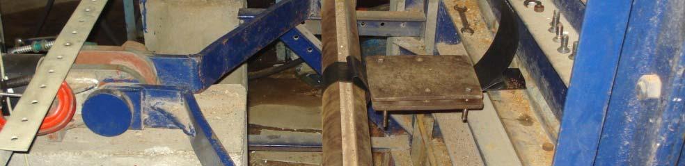
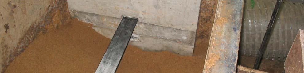
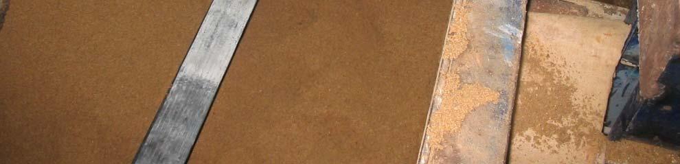
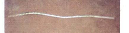
44 Top view of the steel strip and anchor at end steel strip
45 Test series Tests were first performed on steel strip alone Tests on steel strip and anchors were performed at different normal pressures Pullout load applied until about 100 kn maximum load or until peak load Measured data includes: Load, front and rear displacements and strains developed in the steel strip
46 Pullout behaviour of steel strip alone 8 pullout force, kn length of embedment in soil = 1.2 m Depth of embedment = 0.4 m 70 mm wide strip under 100 kpa pressure displacement, mm
47 Displacement Vs Pullout Force relationship for Type I Anchors 80 Pullout Vs Normal Pressure (Type I Anchors) 12 kpa 25 kpa kpa 100 kpa 150 kpa Pullout Force, kn Displacement, mm
48 Pullout behaviour of Type 2 anchors Pullou ut Force, kn Pullout Force Vs Normal Pressure (Type II (large) Anchors) 12 kpa 25 kpa 50 kpa 100 kpa Displacement, mm
49 BS formula for pullout capacity of anchored reinforcement elements Pu Ps Pa 2 Bs v Le 4 K p B a t a v P s = skin friction force P a = passive capacity due to anchor v =normal pressure B s = width of strip L e = embedment length of steep strip B a, t a = width and height of anchor K p = passive pressure coefficient
50 Pullout factor for plain steel strip at 100 kpa pressue Pullout displacement (mm) Load (kn) Pullout factor Pullout factor is higher at lower normal pressures
51 Comparison of results with Type-I anchors with BS 8006 formula and others 60 Comparison Type I Anchors Pullou ut Force, kn Experimental 20 mm Experimental 40 mm BS 8006 Das B M Normal Stress, kpa
52 Comparison of results with Type-II anchors with BS 8006 formula and others BS 8006:1995 Experimental Values (40 mm displacement) Experimental Values (20 mm displacement) Neely's method (Das B M 1990) Pullou ut Force, kn Normal Stress, kpa

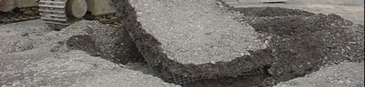
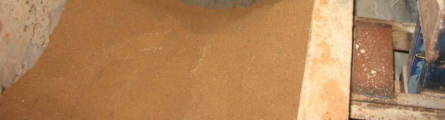
53 Reinforced Soil Walls /59


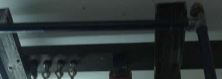
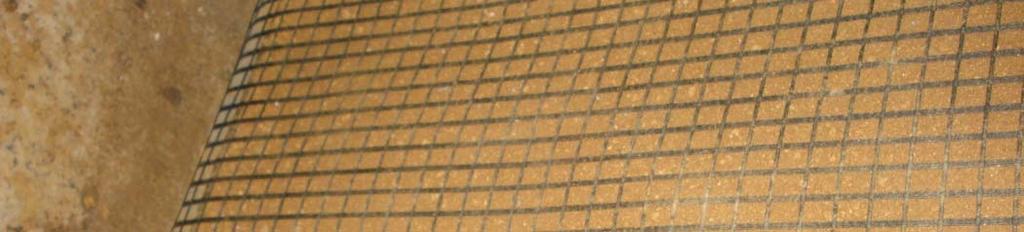
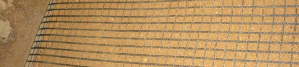
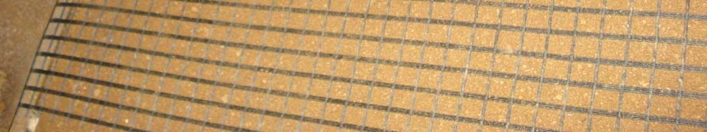
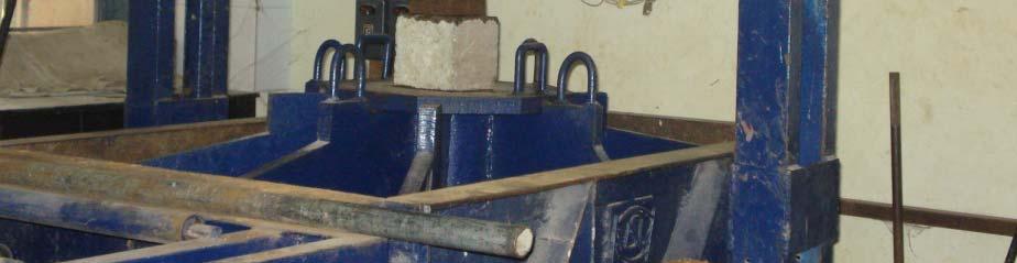
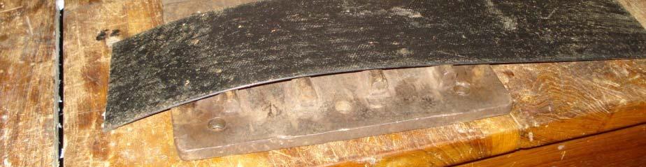
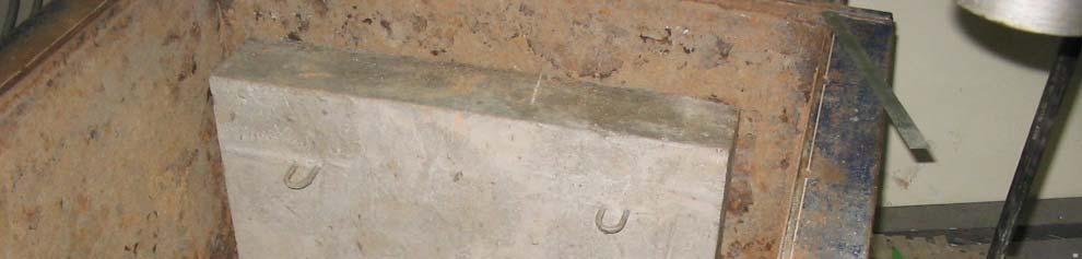
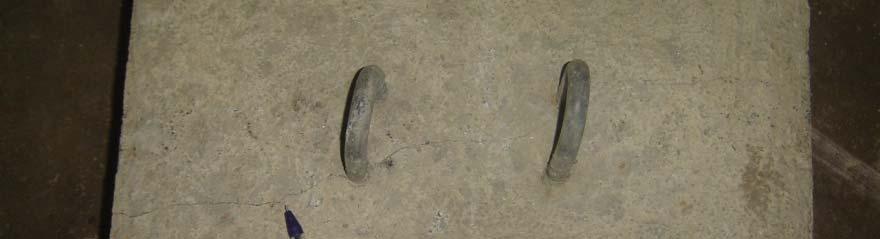
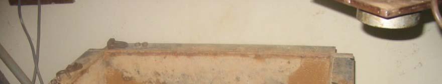
54 Steel mesh with a concrete block anchor


55


56
 (mm) (kn) 40.00 20.")

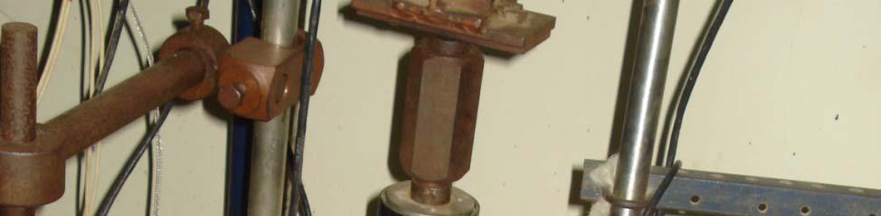
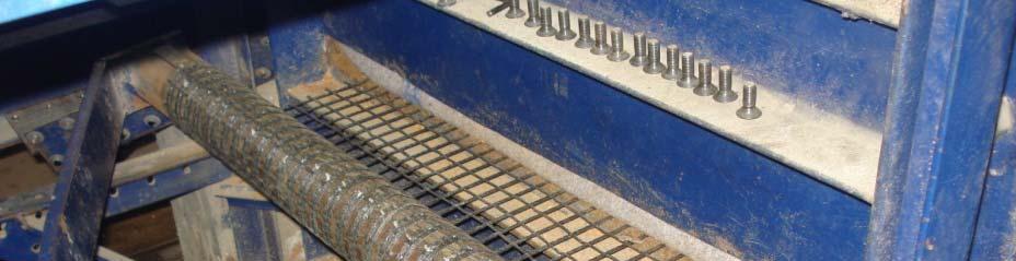
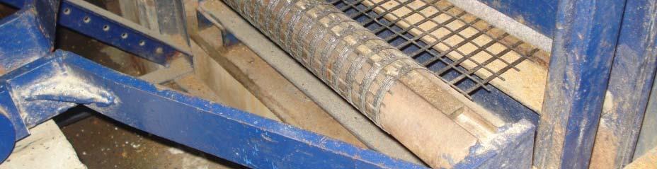
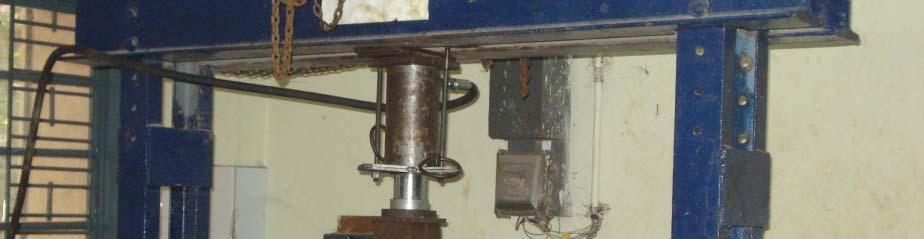
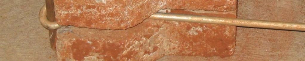
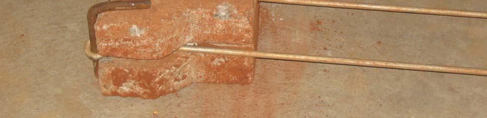
57 Pullout tests on welded mesh with dff different connections Working Limiting Connection load displacement Capacity (kn) (mm) (kn) Working Limiting Connection load displacement Capacity (kn) (mm) (kn) Reinforced Soil Walls /59


58
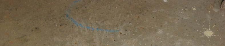
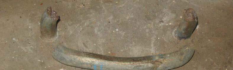
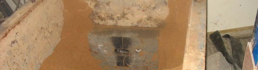

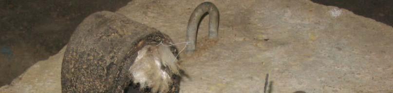
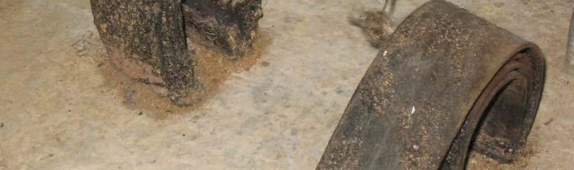

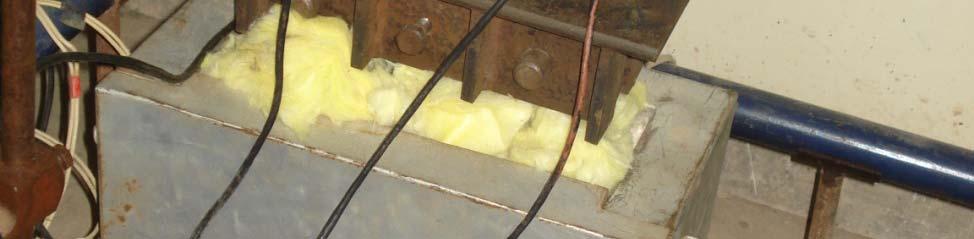
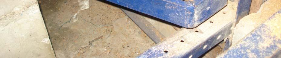
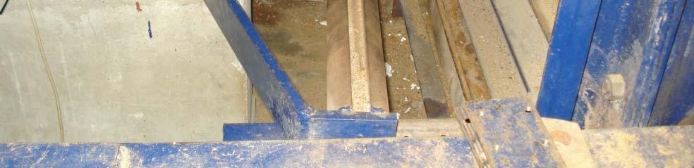
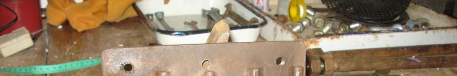
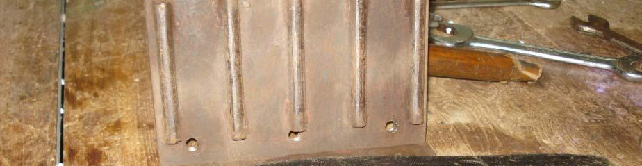
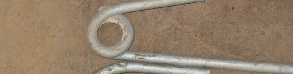
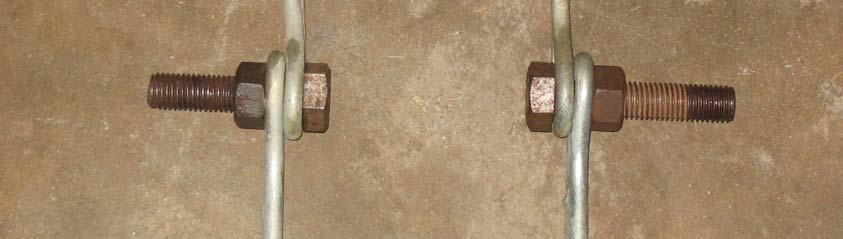
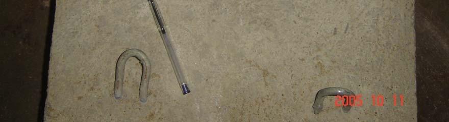
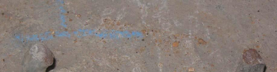
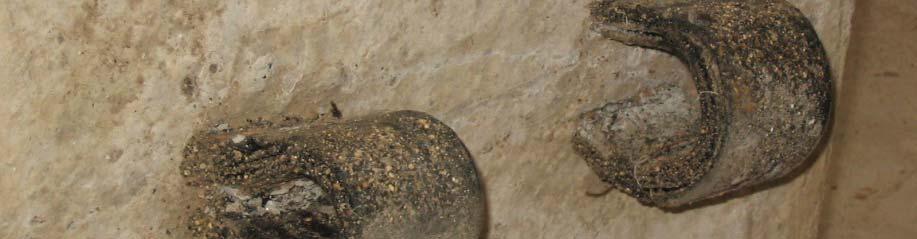
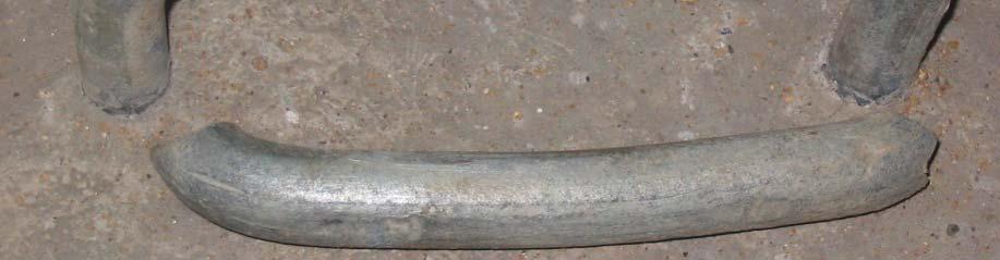
59 Typical connection failures observed in laboratory tests Reinforced Soil Walls /59
60