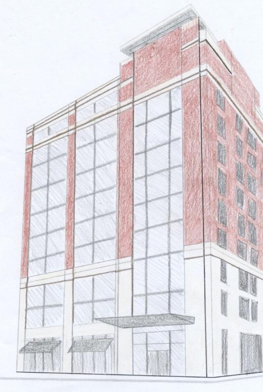
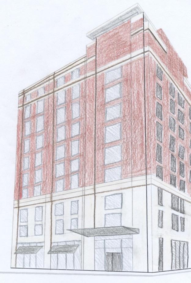
Fairfield Inn and Suites Pittsburgh, PA
|
|
|
- Hortense Armstrong
- 5 years ago
- Views:
Transcription

1
2 Existing Building Information Presentation Outline Construction Management Breadth Study
3 Existing Building Information


4 Location: Downtown Pittsburgh 228 Federal St, Building Statistics: Occupancy - Hotel Size 80,000 SF Stories 10 stories above grade + 1 story below grade Project Cost: $19 million

5 Foundation: Existing Structural System Auger Cast Piles 16 diameter Topped by concrete pilecaps Support 24 x24 reinforced concrete piers Grade Beams 36 to 48 depth Run between pilecaps

6 Gravity System: Existing Structural System Typically 8 precast concrete plank floor Concrete masonry load bearing walls Transfer Beams Columns supporting lobby Lateral Force Resisting System: Concrete masonry shear walls 10 thick walls around perimeter 8 thick walls in core
7 Project Goals


8 Problem Statement Building Weight Poor Soil Site Load bearing walls High base shear value Problem Solution Design lighter structural system Steel Moment Frames Core CMU shear walls


9 Project Goals Structural Depth Study: Reduce overall building weight by redesigning gravity system Optimize the lateral force resisting system Foundation check Façade Breadth Study: Effect of steel frame on façade Construction Management Breadth Study: Impact on construction schedule and cost
10 Structural Depth Study
11 N Framing Plan Moment frames span E-W Frames spaced at 26 and 31 Columns kept at existing locations Columns added around the perimeter Design Loads ASCE 7-05 Live load values Superimposed load values Snow loads Controlling Load Combination: 1.2D + 1.6L + 0.5Lr

12 Live Load = 80 psf Dead Load = 10 psf SDL = 25 psf Hollow Core Plank Design Results using PCI Design Handbook: 78 S 7 strands at 8/16 dia. Max Span = 31-8 Normal weight concrete
13 Beam/Girder Design Criteria Strength Design Criteria: ASCE 7-05 LRFD Load Combinations 1.4D 1.2D + 1.6L + 0.5(L r or S) 1.2D + 1.6L r + 0.5L Serviceability Criteria: Deflection Non-Composite: Dead Load.l/360 Live Load...l/360 Total Load.l/240 Economy Criteria: Camber do NOT camber: Beams that are less than 25ft Beams that requires less that ¾ of camber
 Hand Calc. M u (ft-k) Staad M u (ft-k) φm n (ft-k) Interior Girder W 14x68 13.42 180 187 390 Exterior Girder W 14x90 15.")
14 Beam/Girder Design Optimal members were designed with Staad and checked by hand calculations Example: Typical Girders Member Size Length (ft.) Hand Calc. M u (ft-k) Staad M u (ft-k) φm n (ft-k) Interior Girder W 14x Exterior Girder W 14x
15 W 14X 99 W 14X 99 W 14X 99 W 14X 99 W 14X 99 W 14X 99 W 14X 109 W 14X 109 W 14X 99 W 14X 99 W 14X 109 W 14X 109 W 14X 99 W 14X 99 W 14X 109 W 14X 109 W 14X 99 W 14X 99 W 14X 109 W 14X 109 W 14X 99 W 14X 99 W 14X 109 W 14X 109 W 14X 99 Existing Building Information N Column Design Columns resist gravity loads only Levels 1-5: W14x176 Levels 6-10: W14x99 Columns spliced at 5 th story Floor Size KL (ft) Hand Calc. P u (k) Staad P u (k) φp n (k) 1 W14x W14x Optimal members were determined by Staad and checked with hand calculations


16 Connection Design Moment Frame Connection 4 bolt unstiffened extended end plate beam column flange Seated Connection all bolt unstiffened beam column web Moment Connection Seated Connection L 4x4x1/4 w/ 7/8 bolts Column Splice Connection bolted and welded Column base plate Column Splice Connection
17 Impact on Lateral Loads Seismic Loads control both directions 31% decrease Original Building Design New Building Design Building Weight lbs lbs Base Shear kips kips Total Moment ft-kips ft-kips Controlling Load Combination 0.9D + 1.0E
18 Shear wall layout Shear Wall Design Preliminary shear wall thickness = 10 Wall A Wall B Wall C Wall D Wall E Wall F N

19 Shear Wall Design Reinforcing: axial + flexural strength No horizontal shear reinforcement Vertical: #5 8, 16 & 32 O.C Interaction Diagram


20 Modified shear walls Thicker walls Additional reinforcement ETABS Model Optimization Study Assumptions: Shear wall take full lateral loads Floors modeled as rigid diaphragms Lateral loads distributed based on relative stiffness of each wall Gravity loads as additional area mass to the diaphragms


21 Shift in center of rigidities Optimization Study Increased stiffness to each shear wall Decreased in Overall Building Torsion Overall Building Torsion Modified Design Original Design N/S Direction 1519 ft-k 3346 ft-k E/W Direction 1928 ft-k 2678 ft-k

22 Lateral Drifts ASCE 7-05 calculated drifts Drift Limitations: Wind - H/400 Seismic h sx Optimization Study Lateral drifts due to seismic loads governed Max. drift in N-S direction
23 Impact on Foundation Modified lateral resisting system New material for altered gravity load system Decrease in overall building weight Greater resistance to overturning Overturning Modified Design Original Design N/S Direction ft-k ft-k E/W Direction ft-k ft-k
24 Auger cast Piles 16 diameter Structural System Redesigned Steel System Original Concrete/Masonry System Impact on Foundation Number of Required Piles Comparison of the number of piles to support the new design vs. the original design Column No. Total Load on Each Column (k) # of piles required to support Steel System # of piles used in Original Design % Decrease in required # of piles Not in original Average % Decrease in # Piles Required = 35
25 Conclusions Redesign Strength Serviceability Reduction load bearing walls Reduced building weight Modified Lateral Resisting System Reduced overall building torsion Within drift limits Foundation Overturning resistance Reduced number of piles
26 Façade Breadth Study

27 Façade Breadth Study


28 Between Material Curtain Wall System ΣR o-x ( F ft 2 h/btu) Thermal Gradients Temperature ( F) o i U = (BTU/ F ft 2 h) Between Material Brick Venner System ΣR o-x ( F ft 2 h/btu) Temperature ( F) o i U = (BTU/ F ft 2 h)
29 Wall System Curtain Wall System Brick Veneer System S.F. Cost Comparison Façade Systems with Redesigned Structural System Crew Size Material Cost/SF Labor Cost/SF Total Cost Daily Output Construction Time Glaziers $30.49 $6.94 $214, days Brick Layers $6.95 $8.94 $91, days
30 Conclusions Research façade options on steel framing Determined brick veneer is the most efficient facade thru heat transfer Determined brick veneer is the cost efficient facade
31 Construction Management Breadth Study
32 Redesigned Structural System Start Date: February 26, 2009 Finish Date: April 24, 2009 Original Structural System Start Date: February 26, 2009 Finish Date: August 13, 2009 Construction Schedule Construction Time Comparison Component Existing System Redesigned System (days) (days) Savings (+) Shear Walls Steel Frame Total 99
33 Cost Impact of Redesigned System Costs unaccounted for: Precast Plank floors Foundation costs Additional member connections Example Detailed Cost Breakdown: Shear walls and reinforcement Steel members, base plates, fireproofing Crane Shearwalls Amt. Unit Mat'l Cost/Unit Labor Cost/Unit Equip Cost/Unit Total Cost/Unit Total Cost w/ O&P TOTAL COST 10" CMU Block SF $187, Reinforce. 7 Ton $ 8, Steel Amt. Unit Mat'l Cost/Unit Labor Cost/Unit Equip Cost/Unit Total Cost/Unit Total Cost w/ O&P TOTAL COST Columns 2753 LF $462, Baseplates 108 SF $ 5, Beams 4807 LF $509, Fireproofing 7559 SF $ 24, Crane $ 22,800.00
34 Cost Impact Overall Cost Comparison Component Existing System Redesigned System Additional Cost Shear Walls $519,680 $196,111 -$323,569 Steel Framing $171,660 $1,001,407 $829,747 Crane $10,977 $22,822 $11,845 TOTAL $702,317 $1,220,340 $518,023
35 Conclusions Thesis Structural System Existing Structural System Crane Cost due to Steel $22, $10, Total System Cost $1,220, $702, Steel Erection Schedule (days) Entire Structural System Schedule (days) Steel erection tops out 30 days earlier than the new structural system Structural system construction tops out 99 days earlier than existing structural system
36 Conclusions & Recommendations Gravity System Redesign Steel Moment Frames Reasonable design for gravity loads Meets strength and serviceability requirements Reduced overall building weight Lateral Resisting System Redesign Modified Shear wall design is optimal Foundation No alteration needed Façade Brick veneer is most efficient Construction Management Reduce schedule Increase cost
37 Acknowledgements Atlantic Engineering Services: Tim Jones Robert Bertocchi Massaro Corporation: Brian Miller G.M.McCrossin Contracting: Shawn Steward SNC-Lavalin America: Jeremy Coulombe The Pennsylvania State University: Dr. Ali Memari Prof. M Kevin Parfitt Prof. Robert Holland The entire AE faculty and staff My friends and family for all their continued support.
38 Questions & Comments