Cork, an exceptional raw material
|
|
|
- Kenneth Holmes
- 5 years ago
- Views:
Transcription

1


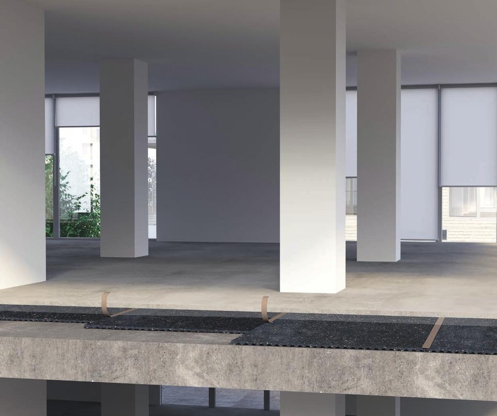
2 Construction Cork, an exceptional raw material Cork is the outer bark of the cork oak tree (Quercus Suber L.), the 100% natural plant tissue covering the trunk and branches. It consists of a honeycomb-like structure of microscopic cells filled with an air-like gas and coated mainly with suberin and lignin. One cubic centimetre of cork contains about 40 million cells. Cork is also known as nature s foam due to its alveolar cellular structure. It has a closed cell structure making it lightweight, airtight and watertight, resistant to acids, fuels and oils, and impervious to rot. Cork cell microscopic view. It is sustainably harvested by specialised professionals without damaging the trunk, thus enabling the tree to grow another layer of outer bark that, in time, will be re-harvested. Over the course of the cork oak tree s life, that lasts 0 years on average, the cork may be stripped around 17 times. This means that cork is not only a natural raw material, it is also renewable and recyclable. Excellent acoustic insulator Excellent thermal insulator Good resilience, excellent compressibility and recovery Extremely light and buoyant 100% natural, reusable and recyclable

3 Efficiency, Resilience and Durability ACOUSTICORK natural base materials for demanding applications Amorim Cork Composites specific compound formulations for acoustic insulation and vibration control allow creating highly insulating or dampening materials able to comply with a wide range of environmental conditions and chemical resistances. ACOUSTICORK maximises energy efficiency Cork absorbs energy due to its unique compressibility and recovery characteristics yielding higher loss factors that are essential for the dampening function, while its extremely low Poisson Ratio improves the behaviour of such material in dynamic loading applications. The combination of cork granules with diverse polymers provides added characteristics to different compounds or use as acoustic or vibration control materials. 1


4 ITECONS attests Acousticork s Performance RESEARCH ITeCons - Institute for Research and Technological Development for Construction, Energy, Environment and Sustainability is a non-profit organization dedicated to providing a dynamic knowledge interface between the scientific community and industry. It has over 50 associate members, including businesses, municipal ties and other research institutions. TECHNICAL ASSESSMENT BODY ITeCons has been accredited by the Portuguese Accreditation Institute to perform over 2 different tests. It operates a certified quality management system, and is a notified body - Testing Laboratory - to perform CE marking. As a Technical Assessment Body, ITeCons is also able to support industry by issuing European Technical Assessments to allow CE marking. TECHNICAL EXPERTISE ITeCons supports companies in their development of new materials and construction systems by helping in the conception, design, characterization and testing stages. Expert consulting activities in construction sciences also includes the detection of construction pathologies in buildings, civil engineering structures and roads. Another service provided by the institute is structural safety assessment and monitoring, looking to identify weaknesses and propose corrective measures to improve structural behaviour. By establishing multiple partnerships with industry and academia, ITeCons has contributed crucially to meeting Europe s societal challenges in the fields of construction, energy, environment and sustainability. 2
5 Acousticork index T22 7 T61 11 T66 15 T85 19 U22 25 U32 29 U85 33 Cork & Natural Rubber Engineered Compound VC VC VC VC VC VC Resin Bonded Cork & Recycled Rubber VC-PAD Resin Bonded Recycled Rubber VC VC VC VC VC70 71 MS-R0 77 MS-R1 79 MS-R2 81 3
6 4

7


8 4,5mm 18dB 52dB * Tested according to MMFA/EPLF requirements 6
9 T22 Material Data Sheet GLUED DOWN WOOD FLOORS 100% Recycled Material Impact Noise Reduction and Thermal Insulation Properties High Durability and Long Term Resilience High Performance with Reduced Thickness UNDERLAY 01 PRODUCT DESCRIPTION Agglomerated recycled rubber underlay for impact noise and thermal insulation. THERMAL PROPERTIES Thermal Conductivity: 0,140 W/mK (1) (1) ISO 8301 PHYSICAL AND MECHANICAL PROPERTIES Specific Weight (1) Tensile Strength (2) Compressibility at 0,7MPa (3) Recovery after 0,7MPa (3) Kg/m 3 > 350 KPa % > 80% (1) ASTM F1315 (2) ASTM F152 (3) ASTM F36 ACOUSTICAL RESULTS Flooring Thickness (mm) ΔL w (db) (1) IIC (db) (2) Glued Down Wood 4 49 (1) ISO and ISO (2) ASTM E & ASTM E STANDARD DIMENSIONS Others sizes available upon request Thickness (mm) 4 Width (m) x Length (m) 1 x 10 7
10 ACOUSTICAL RESULTS Test procedure according to ISO :10; ISO :10; ISO :10 and ISO 717-2:13 standards. Normalized impact pressure level L [db] Frequency [Hz] - Normalized impact sound pressure level of the reference floor with the floor covering under test;,0 - Normalized impact sound pressure level of the Lab reference floor; ΔL w - Impact sound pressure level reduction index of the covering under test, on a normalized floor; ,0 (db) (db) - 4mm TEST APPARATUS (ΔL W & IIC) Floor covering composed by glued down wood Agglomerated recycled rubber resilient layer - T22 Reinforced concrete slab of thickness 140mm Ref. Test Report Thickness Flooring,w (C l,r ) ΔL w (C l,δ ) ACU 128/10 4 mm Glued Down Wood 58 (1) db (-12) db ACOUSTICAL RESULTS Test procedure according to ISO :10; ISO ;10 and ISO :10 standards. Normalized impact sound pressure level and IIC rating determined according ASTM E and ASTM E standards. Normalized impact pressure level L [db] Frequency [Hz] L ref (db) L ref.c (db) - 4mm L ref - Normalized impact sound pressure level of the reference floor with the floor covering under test; L ref.c - Normalized impact sound pressure level of the Lab reference floor; Thickness Flooring IIC c 4mm Glued Down Wood 49dB 8

11 PHYSICAL AND MECHANICAL PROPERTIES LOAD DEFLECTION CREEP 0,0045MPa (% OF START HEIGHT) 5,00 4,00 3,00 2,00 1,00 0,00 0,0 0,5 1,0 1,5 4,0% 3,5% 3,0% 2,5% 2,0% 1,5% 1,0% 0,5% 0,0% UNDERLAY 01 3mm Deflection [mm] Time [h] Note: Following ISO measured in Cantilever Test System DYNAMIC STIFFNESS Test procedure according ISO and ISO standards. Thickness (mm) Dynamic Stiffness (MN/m³) 4 54 INSTALLATION GLUED FLOORS Reinforced concrete slab Adhesive Agglomerated recycled rubber resilient layer - T Floor covering composed by glued down wood Perimeter insulation barrier 9
12 GLUED DOWN WOOD FLOORS ΔL w = db T22... UNDERLAY General Installation Instructions The following installation instructions are recommended by Amorim Cork Composites, but are not intended as a definitive project specification. They are presented in an attempt to be used with recommended installation procedures of the flooring manufacturers. Room Conditions Temperature > 10ºC / Room moisture content < 75%. Subfloor All subfloor work should be structurally sound, clear and level. The moisture content of the subfloor should not be more than 2.5% (CM) by weight measured on concrete subfloors. Installation Instruction for Acousticork T22 Unpack the Acousticork T22 at least 24h before the installation and store it in the room where the installation will take place. Cut the T22 to desired length and install directly over the entire floor pulled 30mm up the walls with crown of the rolled materials up (Acousticork label side down), removing all traped air. After completion, the T22 should cover the entire flooring area without gaps and with joints butted tight and preferably taped. Final Flooring Always follow manufacturers recommended installation instructions. Recommended Adhesives Wood floor to Acousticork: Water-Based Emulsion/ Polyurethane Glue Acousticork to slab/screed: Water-Based Emulsion/ Acrylic Adhesives. Application Process GLUED FLOORS: 1. Perimeter barrier application; 2. Underlay application (glued); 3. Final floor application (glued); 4. Perimeter insulation barrier cut. Important Notes Never mechanically fasten the Acousticork T22 to the flooring floor as this will severaly diminish its acoustical value. For detailed installation instructions, please contact us. The data provided in this Material Data Sheet represents typical values. This information is not intended to be used as a purchasing specification and does not imply suitability for use in a specific application. Failure to select the proper product may result in either equipments damage or personal injury. Please contact Amorim Cork Composites regarding specific application recommendations. Amorim Cork Composites expressly disclaims all warranties, including any implied warranties or merchantability or of fitness for a particular purpose. Amorim Cork Composites is not liable for any indirect special, incidental, consequential, or punitive damages as a result of using the information listed in this MDS. Any of its material specification sheets, its products or any future use or re-use of them by any person or entity. For contractual purposes, please request our Product Specifications Sheet (PDA) ACC Feb 17 EN
13 T61 Material Data Sheet NON GLUED LAMINATE FLOORS GLUED DOWN WOOD FLOORS GLUED DOWN WOOD FLOORS PERFORATED CERAMIC OR NATURAL STONE FLOORS ΔL w = db ΔL w = 26dB ΔL w = 18dB ΔL w = 16dB 100% Natural and Sustainable Product Impact Noise Reduction and Thermal Insulation Properties High Durability and Long Term Resilience High Performance with Reduced Thickness Tested according to MMFA/EPLF requirements Group 1 UNDERLAY 01 PRODUCT DESCRIPTION Agglomerated cork underlay for impact noise and thermal insulation. THERMAL PROPERTIES Thermal Conductivity: 0,04 W/mK (1) (1) ISO 8301 PHYSICAL AND MECHANICAL PROPERTIES (1) ISO 7322 Specific Weight (1) Tensile Strength (1) Compression at 0,7MPa (1) Recovery after 0,7MPa (1) Kg/m 3 > 0 KPa 30% > 70% ACOUSTICAL RESULTS Flooring Thickness (mm) ΔL w (db) (1) IIC (db) (2) Non Glued Laminate 2 54 Glued Down Wood perforated Ceramic (or Natural Stone) (1) ISO and ISO (2) ASTM E & ASTM E STANDARD DIMENSIONS Thickness (mm) perforated 5 Width (m) x Length (m) 1 x 10 1 x 10 0,5 x 10 1 x 10 Others sizes available upon request 11
14 ACOUSTICAL RESULTS Test procedure according to ISO :10; ISO :10; ISO :10 and ISO 717-2:13 standards. Normalized impact pressure level L [db] ,0 (db) (db) - 2mm - Laminate *Glued Down Wood TEST APPARATUS (ΔL W & IIC) (db) - 3mm - GDW* (db) - 3mm perforated- GDW* (db) - 5mm - Ceramic Frequency [Hz] - Normalized impact sound pressure level of the reference floor with the floor covering under test;,0 - Normalized impact sound pressure level of the Lab reference floor; ΔL w - Impact sound pressure level reduction index of the covering under test, on a normalized floor; Floor covering composed by glued down wood, non glued laminate floor or ceramic or natural stone tiles Agglomerated cork resilient layer - T61 Reinforced concrete slab of thickness 140mm Ref. Test Report Thickness Flooring,w (C l,r ) ΔL w (C l,δ ) SRL C/06/5L/3676/1a 2 mm Non Glued Laminate 58 (0) db (-11) db SRL C/06/5L/3676/1a 3 mm Glued Down Wood 52 (1) db 26 (-12) db ACL034/16 3 mm perforated Glued Down Wood 60 (0) db 18 (-11) db SRL C/06/5L/3676/1a 5 mm Ceramic (or Natural Stone) 62 (0) db 16 (-11) db ACOUSTICAL RESULTS Test procedure according to ISO :10; ISO ;10 and ISO :10 standards. Normalized impact sound pressure level and IIC rating determined according ASTM E and ASTM E standards. Normalized impact pressure level L [db] L ref (db) L ref,c (db) - 2mm - Laminate *Glued Down Wood L ref,c (db) - 3mm - GDW* L ref,c (db) - 3mm perforated - GDW* L ref,c (db) - 5mm - Ceramic Frequency [Hz] L ref - Normalized impact sound pressure level of the reference floor with the floor covering under test; L ref.c - Normalized impact sound pressure level of the Lab reference floor; Thickness Flooring IIC c 2 mm Laminate 54 db 3 mm Glued Down Wood 59 db 3 mm perforated Glued Down Wood 51 db 5 mm Ceramic (or Natural Stone) 50 db 12

15 PHYSICAL AND MECHANICAL PROPERTIES LOAD DEFLECTION CREEP 0,0045MPa (% OF START HEIGHT) 1,60 1,40 1, 1,00 0,80 0,60 0,40 0, 4,0% 3,5% 3,0% 2,5% 2,0% 1,5% 1,0% 0,5% UNDERLAY 01 0,00 0,0 0,5 1,0 1,5 2,0 2,5 0,0% Deflection [mm] Time [h] 2mm 3mm 5mm Note: Following ISO measured in Cantilever Test System DYNAMIC STIFFNESS Test procedure according ISO and ISO standards. Thickness (mm) Dynamic Stiffness (MN/m³) INSTALLATION GLUED FLOORS NON GLUED FLOORS Reinforced concrete slab Adhesive Agglomerated cork resilient layer - T61 Floor covering composed by glued down wood, ceramic or nature stone Perimeter insulation barrier Vapor barrier Floor covering composed by non glued laminate floor 13
16 NON GLUED LAMINATE FLOORS ΔL w = db GLUED DOWN WOOD FLOORS GLUED DOWN WOOD FLOORS PERFORATED CERAMIC OR NATURAL STONE FLOORS ΔL w = 26dB ΔL w = 18dB ΔL w = 16dB T61... UNDERLAY General Installation Instructions The following installation instructions are recommended by Amorim Cork Composites, but are not intended as a definitive project specification. They are presented in an attempt to be used with recommended installation procedures of the flooring manufacturers. Room Conditions Temperature > 10ºC / Room moisture content < 75%. Subfloor All subfloor work should be structurally sound, clear and level. The moisture content of the subfloor should not be more than 2.5% (CM) by weight measured on concrete subfloors. Vapor Insulation Barrier (only for Non Glued Floors) PE (Polyethylene) vapor insulation barrier covering the entire flooring area, minimum 50mm wide vertically around the perimeter of the entire floor MUST be installed prior to the Acousticork T61. Install by overlapping (minimum 100mm) the PE foil, and use an adequate tape to adhere/fix it, if necessary. After completion, PE foil should cover the entire concrete area without gaps. Never mechanically fasten the PE foil barrier with screws, nails or staples as this will severely diminish the performance of the insulation barrier. Installation Instruction for Acousticork T61 Unpack the Acousticork T61 at least 24h before the installation and store it in the room where the installation will take place. Cut the T61 to desired length and install directly over the entire floor pulled 30mm up the walls with crown of the rolled materials up (Acousticork label side down), removing all traped air. After completion, the T61 should cover the entire flooring area without gaps and with joints butted tight and preferably taped. Tested according to MMFA/EPLF requirements Group 1 Final Flooring Always follow manufacturers recommended installation instructions. Recommended Adhesives: Wood floor to Acousticork: Water-Based Emulsion/ Polyurethane Glue; Vinyl and linoleum to Acousticork: Water-Based Emulsion/ Synthetic Resin Glue; Ceramic to Acousticork: Flexible Cement Glue; Acousticork to slab/screed: Water-Based Emulsion/ Acrylic Adhesives; Application Process NON GLUED FLOORS: 1. Vapor insulation barrier application; 2. Perimeter barrier application; 3. Underlay application; 4. Tape application in joints between rolls; 5. Final floor application; 6. Perimeter insulation barrier cut. GLUED FLOORS: 1. Perimeter barrier application; 2. Underlay application (glued); 3. Final floor application (glued); 4. Perimeter insulation barrier cut. Important Notes Never mechanically fasten the Acousticork T61 to the flooring floor as this will severaly diminish its acoustical value. For detailed installation instructions, please contact us. The data provided in this Material Data Sheet represents typical values. This information is not intended to be used as a purchasing specification and does not imply suitability for use in a specific application. Failure to select the proper product may result in either equipments damage or personal injury. Please contact Amorim Cork Composites regarding specific application recommendations. Amorim Cork Composites expressly disclaims all warranties, including any implied warranties or merchantability or of fitness for a particular purpose. Amorim Cork Composites is not liable for any indirect special, incidental, consequential, or punitive damages as a result of using the information listed in this MDS. Any of its material specification sheets, its products or any future use or re-use of them by any person or entity. For contractual purposes, please request our Product Specifications Sheet (PDA) ACC Feb 17 EN
17 T66 Material Data Sheet NON GLUED LAMINATE FLOORS GLUED DOWN WOOD FLOORS CERAMIC OR NATURAL STONE FLOORS LVT ΔL w = 19dB ΔL w = 16dB ΔL w = 18dB ΔL w = 19dB Produced from Recycled and Natural Materials Impact Noise Reduction and Thermal Insulation Properties High Durability and Long Term Resilience High Performance with Reduced Thickness UNDERLAY 01 PRODUCT DESCRIPTION Agglomerated cork and recycled rubber underlay for impact noise and thermal insulation. THERMAL PROPERTIES Thermal Conductivity: 0,08 W/mK (1) (1) ISO 8301 PHYSICAL AND MECHANICAL PROPERTIES (1) ISO 7322 Specific Weight (1) Tensile Strength (1) Compression at 0,7MPa (1) Recovery after 0,7MPa (1) Kg/m 3 > 800 KPa 15% > 75% ACOUSTICAL RESULTS Flooring Thickness (mm) ΔL w (db) (1) IIC (db) (2) Non Glued Laminate Glued Down Wood Ceramic (or Natural Stone) , LVT (1) ISO and ISO (2) ASTM E & ASTM E STANDARD DIMENSIONS Others sizes available upon request Thickness (mm) 3 4,5 Width (m) x Length (m) 1 x x 1 0 CASTOR CHAIR RESISTANCE Pass (1) (1) EN
18 ACOUSTICAL RESULTS Test procedure according to ISO :10; ISO :10; ISO :10 and ISO 717-2:13 standards. Normalized impact pressure level L [db] , 0 (db) (db) - 3mm Laminate *Glued Down Wood (db) - 3mm GDW* (db) - 3mm Ceramic TEST APPARATUS (ΔL W & IIC) (db) - 3mm LVT (db) - 4,5mm Ceramic Frequency [Hz] - Normalized impact sound pressure level of the reference floor with the floor covering under test;,0 - Normalized impact sound pressure level of the Lab reference floor; ΔL w - Impact sound pressure level reduction index of the covering under test, on a normalized floor; Floor covering composed by glued down wood, non glued laminate floor or ceramic or natural stone tiles Agglomerated cork and recycled rubber resilient layer - T66 Reinforced concrete slab of thickness 140mm Ref. Test Report Thickness Flooring,w (C l,r ) ΔL w (C l,δ ) ACU 337/11 3mm Non Glued Laminate 59 (2) db 19 (-13) db ACL 127/15 3mm Glued Down Wood 62 (0) db 16 (-11) db ACL 3/14 3mm 62 (-1) db 16 (-10) db Ceramic (or Natural Stone) ACL 063/17 4,5mm 60(-1) db 18 (-10) db ACL 199/14 3mm LVT 59 (0) db 19 (-11) db ACOUSTICAL RESULTS Test procedure according to ISO :10; ISO ;10 and ISO :10 standards. Normalized impact sound pressure level and IIC rating determined according ASTM E and ASTM E standards. Normalized impact pressure level L [db] , 0 (db) (db) - 3mm Laminate *Glued Down Wood (db) - 3mm GDW* (db) - 3mm Ceramic (db) - 3mm LVT (db) - 4,5mm Ceramic Frequency [Hz] L ref - Normalized impact sound pressure level of the reference floor with the floor covering under test; L ref.c - Normalized impact sound pressure level of the Lab reference floor; Thickness Flooring IIC c 3 mm Non Glued Laminate 47 db 3 mm Glued Down Wood 50 db 3 mm 51 db Ceramic (or Natural Stone) 4,5 mm 52 db 3 mm LVT 51 db 16


19 PHYSICAL AND MECHANICAL PROPERTIES LOAD DEFLECTION CREEP 0,0045MPa (% OF START HEIGHT) 3,00 2,00 1,00 4,0% 3,5% 3,0% 2,5% 2,0% 1,5% 1,0% 0,5% UNDERLAY 01 0,00 0,00 0,75 1,50 0,0% Deflection [mm] Time [h] 3mm 4,5mm Note: Following ISO measured in Cantilever Test System DYNAMIC STIFFNESS Test procedure according ISO and ISO standards. Thickness (mm) Dynamic Stiffness (MN/m³) ,5 152 INSTALLATION GLUED FLOORS NON GLUED FLOORS Reinforced concrete slab Adhesive Agglomerated cork and recycled rubber resilient layer - T66 Floor covering composed by glued down wood, ceramic or nature stone Perimeter insulation barrier Vapor barrier Floor covering composed by non glued laminate floor 17
20 NON GLUED LAMINATE FLOORS ΔL w = 19dB GLUED DOWN WOOD FLOORS ΔL w = 16dB T66 CERAMIC OR NATURAL STONE FLOORS ΔL w = 18dB LVT ΔL w = 19dB... UNDERLAY General Installation Instructions The following installation instructions are recommended by Amorim Cork Composites, but are not intended as a definitive project specification. They are presented in an attempt to be used with recommended installation procedures of the flooring manufacturers. Room Conditions Temperature > 10ºC / Room moisture content < 75%. Subfloor All subfloor work should be structurally sound, clear and level. The moisture content of the subfloor should not be more than 2.5% (CM) by weight measured on concrete subfloors. Vapor Insulation Barrier (only for Non Glued Floors) PE (Polyethylene) vapor insulation barrier covering the entire flooring area, minimum 50mm wide vertically around the perimeter of the entire floor MUST be installed prior to the Acousticork T66. Install by overlapping (minimum 100mm) the PE foil, and use an adequate tape to adhere/fix it, if necessary. After completion, PE foil should cover the entire concrete area without gaps. Never mechanically fasten the PE foil barrier with screws, nails or staples as this will severely diminish the performance of the insulation barrier. Installation Instruction for Acousticork T66 Unpack the Acousticork T66 at least 24h before the installation and store it in the room where the installation will take place. Cut the T66 to desired length and install directly over the entire floor pulled 30mm up the walls with crown of the rolled materials up (Acousticork label side down), removing all traped air. After completion, the T66 should cover the entire flooring area without gaps and with joints butted tight and preferably taped. Final Flooring Always follow manufacturers recommended installation instructions. Recommended Adhesives: Wood floor to Acousticork: Water-Based Emulsion/ Polyurethane Glue; Vinyl and linoleum to Acousticork: Water-Based Emulsion/ Synthetic Resin Glue; Ceramic to Acousticork: Flexible Cement Glue; Acousticork to slab/screed: Water-Based Emulsion/ Acrylic Adhesives; Application Process NON GLUED FLOORS: 1. Vapor insulation barrier application; 2. Perimeter barrier application; 3. Underlay application; 4. Tape application in joints between rolls; 5. Final floor application; 6. Perimeter insulation barrier cut. GLUED FLOORS: 1. Perimeter barrier application; 2. Underlay application (glued); 3. Final floor application (glued); 4. Perimeter insulation barrier cut. Important Notes Never mechanically fasten the Acousticork T66 to the flooring floor as this will severaly diminish its acoustical value. For detailed installation instructions, please contact us. The data provided in this Material Data Sheet represents typical values. This information is not intended to be used as a purchasing specification and does not imply suitability for use in a specific application. Failure to select the proper product may result in either equipments damage or personal injury. Please contact Amorim Cork Composites regarding specific application recommendations. Amorim Cork Composites expressly disclaims all warranties, including any implied warranties or merchantability or of fitness for a particular purpose. Amorim Cork Composites is not liable for any indirect special, incidental, consequential, or punitive damages as a result of using the information listed in this MDS. Any of its material specification sheets, its products or any future use or re-use of them by any person or entity. For contractual purposes, please request our Product Specifications Sheet (PDA) ACC Jun 17 EN
21 T85 Material Data Sheet UNDERLAY NON GLUED LAMINATE FLOORS GLUED DOWN WOOD FLOORS CERAMIC OR NATURAL STONE FLOORS LVT ΔL w = 19dB ΔL w = 14dB ΔL w = 12dB ΔL w = 17dB Produced from Recycled and Natural Materials Impact Noise Reduction and Thermal Insulation Properties High Durability and Long Term Resilience High Performance with Reduced Thickness Tested according to MMFA/EPLF requirements Group 1 01 PRODUCT DESCRIPTION Agglomerated cork with recycled polyurethane underlay for impact noise insulation. THERMAL PROPERTIES Thermal Conductivity: 0,055 W/mK (1) (1) EN PHYSICAL AND MECHANICAL PROPERTIES (1) ISO 7322 Specific Weight (1) Tensile Strength (1) Compression at 0,7MPa (1) Recovery after 0,7MPa (1) kg/m 3 > 100 KPa 30% > 70% ACOUSTICAL RESULTS Flooring Thickness (mm) ΔL w (db) (1) IIC (db) (2) Non Glued Laminate Glued Down Wood Ceramic (or Natural Stone) , LVT 2-54 (1) ISO and ISO (2) ASTM E & ASTM E STANDARD DIMENSIONS Thickness (mm) 1,6 2 Width (m) x Length (m) 1 x x 1 0 Others sizes available upon request CASTOR CHAIR RESISTANCE Pass (Ref. Test Report OMC 025/14) (1) (1) EN
22 ACOUSTICAL RESULTS Test procedure according to ISO :10; ISO :10; ISO :10 and ISO 717-2:13 standards. Normalized impact pressure level L [db] , 0 (db) (db) - 2mm Laminate *Glued Down Wood *Except 2mm LVT (db) - 2mm GDW* (db) - 2mm Ceramic TEST APPARATUS (ΔL W & IIC*) (db) - 1,6mm LVT Frequency [Hz] - Normalized impact sound pressure level of the reference floor with the floor covering under test;,0 - Normalized impact sound pressure level of the Lab reference floor; ΔL w - Impact sound pressure level reduction index of the covering under test, on a normalized floor; Floor covering composed by glued down wood, non glued laminate floor or ceramic or natural stone tiles Agglomerated cork and PU resilient layer - T85 Reinforced concrete slab of thickness 140mm Ref. Test Report Thickness Flooring,w (C l,r ) ΔL w (C l,δ ) ACL035/16 Non Glued Laminate 59 (1) db 19 (-12) db ACL 169/15 2 mm Glued Down Wood 64 (-2) db 14 (-9) db ACL 125/15 Ceramic (or Natural Stone) 66 (-4) db 12 (-7) db ACL036/16 1,6 mm LVT 61 (-1) db 17 (-10) db ACOUSTICAL RESULTS Test procedure according to ISO :10; ISO ;10 and ISO :10 standards. Normalized impact sound pressure level and IIC rating determined according ASTM E and ASTM E standards. Normalized impact pressure level L [db] L ref (db) L ref,c (db) - 2mm GDW* L ref,c (db) - 1,6mm LVT** L ref,c (db) - 2mm Laminate L ref,c (db) - 2mm Ceramic L ref,c (db) - 2mm LVT *Glued Down Wood ** Test Procedure according to standards ASTM E TEST APPARATUS (IIC*) *Only 2mm LVT Frequency [Hz] L ref - Normalized impact sound pressure level of the reference floor with the floor covering under test; L ref.c - Normalized impact sound pressure level of the Lab reference floor; Floor covering composed by LVT Agglomerated cork and PU resilient layer - T85 Reinforced concrete slab of thickness 3mm Thickness Flooring IIC c Non Glued Laminate 49 db 2 mm Glued Down Wood 49 db Ceramic (or Natural Stone) 46 db 1,6 mm LVT 52 db 2 mm LVT 54 db

23 PHYSICAL AND MECHANICAL PROPERTIES LOAD DEFLECTION CREEP 0,0045MPa (% OF START HEIGHT) 0,70 0,60 0,50 0,40 0,30 0, 0,10 8,0% 7,0% 6,0% 5,0% 4,0% 3,0% 2,0% 1,0% UNDERLAY 01 0,00 0,0 0,2 0,4 0,6 0,8 1,0 0,0% Deflection [mm] Time [h] 1,6mm 2mm Note: Following ISO measured in Cantilever Test System DYNAMIC STIFFNESS Test procedure according ISO and ISO standards. Thickness (mm) Dynamic Stiffness (MN/m³) 1, INSTALLATION GLUED FLOORS NON GLUED FLOORS Reinforced concrete slab Adhesive Agglomerated cork and PU resilient layer - T85 Floor covering composed by glued down wood, ceramic or nature stone Perimeter insulation barrier Vapor barrier Floor covering composed by non glued laminate floor 21
24 NON GLUED LAMINATE FLOORS ΔL w = 19dB GLUED DOWN WOOD FLOORS CERAMIC OR NATURAL STONE FLOORS LVT ΔL w = 14dB ΔL w = 12dB ΔL w = 17dB T85... UNDERLAY General Installation Instructions The following installation instructions are recommended by Amorim Cork Composites, but are not intended as a definitive project specification. They are presented in an attempt to be used with recommended installation procedures of the flooring manufacturers. Room Conditions Temperature > 10ºC / Room moisture content < 75%. Subfloor All subfloor work should be structurally sound, clear and level. The moisture content of the subfloor should not be more than 2.5% (CM) by weight measured on concrete subfloors. Vapor Insulation Barrier (only for Non Glued Floors) PE (Polyethylene) vapor insulation barrier covering the entire flooring area, minimum 50mm wide vertically around the perimeter of the entire floor MUST be installed prior to the Acousticork T85. Install by overlapping (minimum 100mm) the PE foil, and use an adequate tape to adhere/fix it, if necessary. After completion, PE foil should cover the entire concrete area without gaps. Never mechanically fasten the PE foil barrier with screws, nails or staples as this will severely diminish the performance of the insulation barrier. Installation Instruction for Acousticork T85 Unpack the Acousticork T85 at least 24h before the installation and store it in the room where the installation will take place. Cut the T85 to desired length and install directly over the entire floor pulled 30mm up the walls with crown of the rolled materials up (Acousticork label side down), removing all traped air. After completion, the T85 should cover the entire flooring area without gaps and with joints butted tight and preferably taped. Final Flooring Always follow manufacturers recommended installation instructions. Recommended Adhesives Wood floor to Acousticork: Water-Based Emulsion/ Polyurethane Glue; Vinyl and linoleum to Acousticork: Water-Based Emulsion/ Synthetic Resin Glue; Ceramic to Acousticork: Flexible Cement Glue; Acousticork to slab/screed: Water-Based Emulsion/ Acrylic Adhesives; Application Process NON GLUED FLOORS: 1. Vapor insulation barrier application; 2. Perimeter barrier application; 3. Underlay application; 4. Tape application in joints between rolls; 5. Final floor application; 6. Perimeter insulation barrier cut. GLUED FLOORS: 1. Perimeter barrier application; 2. Underlay application (glued); 3. Final floor application (glued); 4. Perimeter insulation barrier cut. Important Notes Never mechanically fasten the Acousticork T85 to the flooring floor as this will severaly diminish its acoustical value. For detailed installation instructions, please contact us. The data provided in this Material Data Sheet represents typical values. This information is not intended to be used as a purchasing specification and does not imply suitability for use in a specific application. Failure to select the proper product may result in either equipments damage or personal injury. Please contact Amorim Cork Composites regarding specific application recommendations. Amorim Cork Composites expressly disclaims all warranties, including any implied warranties or merchantability or of fitness for a particular purpose. Amorim Cork Composites is not liable for any indirect special, incidental, consequential, or punitive damages as a result of using the information listed in this MDS. Any of its material specification sheets, its products or any future use or re-use of them by any person or entity. For contractual purposes, please request our Product Specifications Sheet (PDA) ACC Feb 17 EN

25 UNDERSCREED 02


26 24
27 U22 Material Data Sheet FLOATING SCREED Impact Noise Reduction and Thermal Insulation Properties Very Easy to Handle and Long Term Resilience 100% Recycled Material Very Flexible PRODUCT DESCRIPTION Agglomerated recycled rubber resilient layer for impact noise insulation of floating screed. THERMAL PROPERTIES Thermal Conductivity: 0,140 W/mK (1) (1) ISO 8301 UNDERSCREED 02 PHYSICAL AND MECHANICAL PROPERTIES Specific Weight (1) Dynamic Stiffness (2) Tensile Strength (3) Recovery after 0,7MPa (4) Kg/m 3 MN/m 3 > 350 KPa > 80% (1) ASTM F1315 (2) ISO & ISO (3) ASTM F152 (4) ASTM F36 ACOUSTICAL RESULTS Thickness (mm) ΔL w (db) (1) IIC (db) (2) / / / /5 - - (1) ISO and ISO (2) ASTM E & ASTM E STANDARD DIMENSIONS Thickness (mm) 4 4/2 6 6/3 8 8/ /5 Width (m) x Length (m) 1 x 15 1 x 30 1 x 10 1 x 1 x 10 1 x 15 1 x 10 1 x 10 Others sizes available upon request 25
28 ACOUSTICAL RESULTS Test procedure according to ISO :10; ISO :10; ISO :10 and ISO 717-2:13 standards. Normalized impact pressure level L [db] Frequency [Hz] - Normalized impact sound pressure level of the reference floor with the floor covering under test;,0 - Normalized impact sound pressure level of the Lab reference floor; ΔL w - Impact sound pressure level reduction index of the covering under test, on a normalized floor; , 0 (db) (db) - 4mm Concrete floating screed with 70mm thickness (db) - 6mm (db) - 8mm TEST APPARATUS (ΔL W & IIC) Agglomerated recycled rubber resilient layer - U22 (db) - 8/4mm (db) - 10mm Reinforced concrete slab of thickness 140mm Ref. Test Report Thickness,w (C l,r ) ΔL w (C l,δ ) ACL 102/15 4 mm 56 (2) db 22 (-12) db ACL 101/15 6 mm 56 (1) db 22 (-12) db ACL 099/15 8 mm 55 (1) db 23 (-12) db ACL 168/15 8/4mm 55 (1) db 23 (-12) db ACL 100/15 10 mm 55 (1) db 23 (-12) db Concrete floating screed with 70mm thickness Agglomerated recycled rubber resilient layer with one face dimpled - U22 Profile Reinforced concrete slab of thickness 140mm Normalized impact pressure level L [db] ACOUSTICAL RESULTS Test procedure according to ISO :10; ISO ;10 and ISO :10 standards. Normalized impact sound pressure level and IIC rating determined according ASTM E and ASTM E standards L ref (db) L ref (db) - 4mm L ref (db) - 6mm L ref (db) - 8mm L ref (db) - 8/4mm L ref (db) - 10mm Frequency [Hz] L ref - Normalized impact sound pressure level of the reference floor with the floor covering under test; L ref.c - Normalized impact sound pressure level of the Lab reference floor; Thickness 4mm 6mm 8mm 8/4mm 10mm IIC c 50 db 50 db 51 db 51 db 51 db 26
29 PHYSICAL AND MECHANICAL PROPERTIES LOAD DEFLECTION 10,00 8,00 6,00 4,00 2,00 CREEP 0,0045MPa (% OF START HEIGHT) 4,0% 3,5% 3,0% 2,5% 2,0% 1,5% 1,0% 0,5% 0,00 0,0 0,5 1,0 1,5 2,0 2,5 3,0 3,5 4,0 4,5 5,0 0,0% mm 4/2mm 6mm 6/3mm DYNAMIC STIFFNESS Deflection [mm] 8mm 10mm Profile Flat 8/4mm 10/5mm Test procedure according ISO and ISO standards. Time [h] Note: Following ISO measured in Cantilever Test System UNDERSCREED Thickness 4mm 4/2mm 6mm 6/3mm 8mm 8/4mm 10mm 10/5mm Dynamic Stiffness (MN/m³) INSTALLATION Reinforced concrete slab Vapor barrier Agglomerated recycled rubber resilient layer with one face dimpled - U22 Profile Concrete floating screed Perimeter insulation barrier Adhesive tape Agglomerated recycled rubber resilient layer - U22 27

30 FLOATING SCREED U22... UNDERSCREED General Installation Instructions The following installation instructions are recommended by Amorim Cork Composites, but are not intended as a definitive project specification. They are presented in an attempt to be used with recommended installation procedures of the flooring manufacturers and screed. Room Conditions Temperature > -5ºC / Room moisture content < 75%. Subfloor All subfloor work should be structurally sound, clear and level. The moisture content of the subfloor should not be more than 2.5% (CM) by weight measured on concrete subfloors. Perimeter Insulation Barrier Install a perimeter insulation barrier vertically around the entire perimeter of the room with width equal to that of the floor build up. This is highly recommended in order to avoid lateral propagation of impact noise. The barrier must also be applied in the perimeter of pipes, ducts or any other component protruding from the floor. Spot adhere the strips to the wall using acrylic glue or a bead of silicone sealant. Installation Instruction for Acousticork U22 Unpack the Acousticork U22 at least 24h before the installation and store it in the room where the installation will take place. Cut and trim the Acousticork U22 to the desined size to fit the installation. Apply directly over the subfloor. Always ensure that material is installed to fit the application avoiding the creation of waves in the material. In case of profile material, dimple side must face down. Place the Acousticork U22 directly against the insulation perimeter barrier already installed. Proceed to cover the entire floor making sure that the joints are butted tight and use an adequate tape to fix it. After completion, the Acousticork U22 should cover the entire flooring area without gaps and with joints securely taped. An waterproof membrane (ex. Polyethylene foil) minimum 0.2mm covering the entire flooring area MUST be installed prior to the screed. Install it, minimum 150mm wide vertically and overlapping it, minimum 100mm. After completion, the insulation vapour barrier should cover the entire Acousticork U22 area without gaps. Never mechanically fasten the Acousticork U22 and/or the PE foil barrier with screws, nails or staples as this will severely diminish the performance of the insulation barrier. Screed and Final Flooring Cast a suitable screed over the loose laid PE foil previously installed over the product. Always follow manufacturers recommended installation instructions. For detailed installation instructions, please contact us. The data provided in this Material Data Sheet represents typical values. This information is not intended to be used as a purchasing specification and does not imply suitability for use in a specific application. Failure to select the proper product may result in either equipments damage or personal injury. Please contact Amorim Cork Composites regarding specific application recommendations. Amorim Cork Composites expressly disclaims all warranties, including any implied warranties or merchantability or of fitness for a particular purpose. Amorim Cork Composites is not liable for any indirect special, incidental, consequential, or punitive damages as a result of using the information listed in this MDS. Any of its material specification sheets, its products or any future use or re-use of them by any person or entity. For contractual purposes, please request our Product Specifications Sheet (PDA) ACC Feb 17 EN
31 U32 Material Data Sheet FLOATING SCREED Impact Noise Reduction and Thermal Insulation Properties Very Easy to Handle and Long Term Resilience 100% Natural and Sustainable Product Very Flexible PRODUCT DESCRIPTION Agglomerated cork resilient layer for impact noise insulation of floating screed. UNDERSCREED THERMAL PROPERTIES Thermal Conductivity: 0,04 W/mK (1) (1) ISO PHYSICAL AND MECHANICAL PROPERTIES Specific Weight (1) Dynamic Stiffness (2) Tensile Strength (3) Recovery after 0,7MPa (4) Kg/m 3 38 MN/m 3 > 0 KPa > 70% (1) ASTM F1315 (2) ISO & ISO (3) ASTM F152 (4) ASTM F36 ACOUSTICAL RESULTS Thickness (mm) ΔL w (db) (1) IIC (db) (2) / / / / (1) ISO and ISO (2) ASTM E & ASTM E STANDARD DIMENSIONS Thickness (mm) 4 4/2 6 6/3 8/ /5 Width (m) x Length (m) 1 x 1 x 30 1 x 1 x 1 x 15 1 x 15 1 x 10 Others sizes available upon request 29
32 Normalized impact pressure level L [db] ACOUSTICAL RESULTS Test procedure according to ISO :10; ISO :10; ISO :10 and ISO 717-2:13 standards Frequency [Hz] - Normalized impact sound pressure level of the reference floor with the floor covering under test;,0 - Normalized impact sound pressure level of the Lab reference floor; ΔL w - Impact sound pressure level reduction index of the covering under test, on a normalized floor; , 0 (db) (db) - 4mm Concrete floating screed with 70mm thickness (db) - 4/2mm (db) - 6mm TEST APPARATUS (ΔL W & IIC) Agglomerated cork resilient layer - U32 (db) - 6/3mm, (db) - 8/4mm Reinforced concrete slab of thickness 140mm, 0 (db) - 10mm (db) - 10/5mm Ref. Test Report Thickness,w (C l,r ) ΔL w (C l,δ ) ACL104/15 4 mm 59 (1) db 19 (-12) db ACL041/14 4/2 mm 59 (1) db 19 (-12) db ACL105/15 6 mm 58 (2) db (-13) db ACL042/14 6/3 mm 58 (1) db (-12) db ACU242/09 8/4 mm 57 (7) db 21 (-18) db ACL106/15 10 mm 58 (0) db (-11) db ACL107/15 10/5 mm 56 (3) db 22 (-14) db Concrete floating screed with 70mm thickness Agglomerated cork resilient layer with one face dimpled - U32 Profile Reinforced concrete slab of thickness 140mm ACOUSTICAL RESULTS Test procedure according to ISO :10; ISO ;10 and ISO :10 standards. Normalized impact sound pressure level and IIC rating determined according ASTM E and ASTM E standards. Normalized impact pressure level L [db] Frequency [Hz] , 0 (db) (db) - 4mm (db) - 4/2mm (db) - 6mm (db) - 6/3mm, (db) - 8/4mm, 0 (db) - 10mm (db) - 10/5mm L ref - Normalized impact sound pressure level of the reference floor with the floor covering under test; L ref.c - Normalized impact sound pressure level of the Lab reference floor; Thickness IIC c 4 mm 47 db 4/2 mm 47 db 6 mm 48 db 6/3 mm 48 db 8/4 mm 42 db 10 mm 50 db 10/5 mm 47 db 30


33 PHYSICAL AND MECHANICAL PROPERTIES LOAD DEFLECTION 1,50 CREEP 0,0045MPa (% OF START HEIGHT) 4,0% 3,5% 1,00 0,50 3,0% 2,5% 2,0% 1,5% 1,0% 0,00 0,0 0,5 1,0 1,5 2,0 2,5 3,0 3,5 4,0 4,5 5,0 0,5% 0,0% Deflection [mm] Time [h] 4mm 6mm 8mm 10mm Profile Flat 4/2mm 6/3mm 8/4mm 10/5mm Note: Following ISO measured in Cantilever Test System DYNAMIC STIFFNESS Test procedure according ISO and ISO standards. UNDERSCREED Thickness 4mm 4/2mm 6mm 6/3mm 8mm 8/4mm 10mm 10/5mm Dynamic Stiffness (MN/m³) INSTALLATION Reinforced concrete slab Vapor barrier Agglomerated cork resilient layer with one face dimpled - U32 Profile Concrete floating screed Perimeter insulation barrier Adhesive tape Agglomerated cork resilient layer - U32 31

34 FLOATING SCREED U32... UNDERSCREED General Installation Instructions The following installation instructions are recommended by Amorim Cork Composites, but are not intended as a definitive project specification. They are presented in an attempt to be used with recommended installation procedures of the flooring manufacturers and screed. Room Conditions Temperature > -5ºC / Room moisture content < 75%. Subfloor All subfloor work should be structurally sound, clear and level. The moisture content of the subfloor should not be more than 2.5% (CM) by weight measured on concrete subfloors. Perimeter Insulation Barrier Install a perimeter insulation barrier vertically around the entire perimeter of the room with width equal to that of the floor build up. This is highly recommended in order to avoid lateral propagation of impact noise. The barrier must also be applied in the perimeter of pipes, ducts or any other component protruding from the floor. Spot adhere the strips to the wall using acrylic glue or a bead of silicone sealant. Installation Instruction for Acousticork U32 Unpack the Acousticork U32 at least 24h before the installation and store it in the room where the installation will take place. Cut and trim the Acousticork U32 to the desined size to fit the installation. Apply directly over the subfloor. Always ensure that material is installed to fit the application avoiding the creation of waves in the material. In case of profile material, dimple side must face down. Place the Acousticork U32 directly against the insulation perimeter barrier already installed. Proceed to cover the entire floor making sure that the joints are butted tight and use an adequate tape to fix it. After completion, the Acousticork U32 should cover the entire flooring area without gaps and with joints securely taped. An waterproof membrane (ex. Polyethylene foil) minimum 0.2mm covering the entire flooring area MUST be installed prior to the screed. Install it, minimum 150mm wide vertically and overlapping it, minimum 100mm. After completion, the insulation vapour barrier should cover the entire Acousticork U32 area without gaps. Never mechanically fasten the Acousticork U32 and/or the PE foil barrier with screws, nails or staples as this will severely diminish the performance of the insulation barrier. Screed and Final Flooring Cast a suitable screed over the loose laid PE foil previously installed over the product. Always follow manufacturers recommended installation instructions. For detailed installation instructions, please contact us. The data provided in this Material Data Sheet represents typical values. This information is not intended to be used as a purchasing specification and does not imply suitability for use in a specific application. Failure to select the proper product may result in either equipments damage or personal injury. Please contact Amorim Cork Composites regarding specific application recommendations. Amorim Cork Composites expressly disclaims all warranties, including any implied warranties or merchantability or of fitness for a particular purpose. Amorim Cork Composites is not liable for any indirect special, incidental, consequential, or punitive damages as a result of using the information listed in this MDS. Any of its material specification sheets, its products or any future use or re-use of them by any person or entity. For contractual purposes, please request our Product Specifications Sheet (PDA) ACC Feb 17 EN
35 U85 Material Data Sheet FLOATING SCREED Impact Noise Reduction and Thermal Insulation Properties Very Easy to Handle and Long Term Resilience Produced from Recycled and Natural Material Very Flexible PRODUCT DESCRIPTION Agglomerated cork with recycled polyurethane resilient layer for impact noise insulation of floating screed. UNDERSCREED THERMAL PROPERTIES Thermal Conductivity: 0,055 W/mK (1) (1) ISO PHYSICAL AND MECHANICAL PROPERTIES Specific Weight (1) Dynamic Stiffness (2) Tensile Strength (3) Recovery after 0,7MPa (4) Kg/m 3 27 MN/m 3 > 100 KPa > 70% (1) ASTM F1315 (2) ISO & ISO (3) ASTM F152 (4) ASTM F36 ACOUSTICAL RESULTS Thickness (mm) ΔL w (db) (1) IIC (db) (2) / / / / (1) ISO and ISO (2) ASTM E & ASTM E STANDARD DIMENSIONS Thickness (mm) 4 4/2 6 6/3 8/4 10/5 Width (m) x Length (m) 1 x 15 1 x 30 1 x 10 1 x 1 x 15 1x10 Others sizes available upon request 33
36 ACOUSTICAL RESULTS Test procedure according to ISO :10; ISO :10; ISO :10 and ISO 717-2:13 standards. Normalized impact pressure level L [db] Frequency [Hz] - Normalized impact sound pressure level of the reference floor with the floor covering under test;,0 - Normalized impact sound pressure level of the Lab reference floor; ΔL w - Impact sound pressure level reduction index of the covering under test, on a normalized floor; , 0 (db) (db) - 4mm (db) - 10/5mm Concrete floating screed with 70mm thickness (db) - 6mm (db) - 6/3mm TEST APPARATUS (ΔL W & IIC) Agglomerated cork and PU resilient layer - U85 (db) - 4/2mm (db) - 8/4mm Reinforced concrete slab of thickness 140mm Ref. Test Report Thickness,w (C l,r ) ΔL w (C l,δ ) ACL219/14 4 mm 59 (0) db 19 (-11) db ACL311/15 4/2 mm 55 (1) db 23 (-12) db ACL2/14 6 mm 58 (0) db (-11) db ACL171/15 6/3 mm 55 (1) db 23 (-12) db ACL122/15 8/4mm 53 (2) db 25 (-13) db ACL121/15 10/5mm 51 (3) db 27 (-14) db Normalized impact pressure level L [db] ACOUSTICAL RESULTS Test procedure according to ISO :10; ISO ;10 and ISO :10 standards. Normalized impact sound pressure level and IIC rating determined according ASTM E and ASTM E standards Concrete floating screed with 70mm thickness, 0 (db) (db) - 4mm (db) - 10/5mm Agglomerated cork and PU resilient layer with one face dimpled - U85 Profile (db) - 6mm (db) - 6/3mm Reinforced concrete slab of thickness 140mm (db) - 4/2mm (db) - 8/4mm Frequency [Hz] L ref - Normalized impact sound pressure level of the reference floor with the floor covering under test; L ref.c - Normalized impact sound pressure level of the Lab reference floor; Thickness IIC c 4 mm 51 db 4/2 mm 52 db 6 mm 51 db 6/3 mm 52 db 8/4mm 52 db 10/5mm 52 db 34


37 PHYSICAL AND MECHANICAL PROPERTIES LOAD DEFLECTION 0,90 0,75 0,60 0,45 0,30 0,15 CREEP 0,0045MPa (% OF START HEIGHT) 8,0% 7,0% 6,0% 5,0% 4,0% 3,0% 2,0% 1,0% 0, ,0% Deflection [mm] Time [h] 4mm 6mm 8mm 10mm Profile Flat 4/2mm 6/3mm 8/4mm 10/5mm Note: Following ISO measured in Cantilever Test System DYNAMIC STIFFNESS Test procedure according ISO and ISO standards. UNDERSCREED Thickness 4mm 4/2mm 6mm 6/3mm 8mm 8/4mm 10mm 10/5mm Dynamic Stiffness (MN/m³) INSTALLATION Reinforced concrete slab Vapor barrier Agglomerated cork and PU resilient layer with one face dimpled - U85 Profile Concrete floating screed Perimeter insulation barrier Adhesive tape Agglomerated cork and PU resilient layer - U85 35

 by weight measured on concrete subfloors.")
38 FLOATING SCREED U85... UNDERSCREED General Installation Instructions The following installation instructions are recommended by Amorim Cork Composites, but are not intended as a definitive project specification. They are presented in an attempt to be used with recommended installation procedures of the flooring manufacturers and screed. Room Conditions Temperature > -5ºC / Room moisture content < 75%. Subfloor All subfloor work should be structurally sound, clear and level. The moisture content of the subfloor should not be more than 2.5% (CM) by weight measured on concrete subfloors. Perimeter Insulation Barrier Install a perimeter insulation barrier vertically around the entire perimeter of the room with width equal to that of the floor build up. This is highly recommended in order to avoid lateral propagation of impact noise. The barrier must also be applied in the perimeter of pipes, ducts or any other component protruding from the floor. Spot adhere the strips to the wall using acrylic glue or a bead of silicone sealant. Installation Instruction for Acousticork U85 Unpack the Acousticork U85 at least 24h before the installation and store it in the room where the installation will take place. Cut and trim the Acousticork U85 to the desined size to fit the installation. Apply directly over the subfloor. Always ensure that material is installed to fit the application avoiding the creation of waves in the material. In case of profile material, dimple side must face down. Place the Acousticork U85 directly against the insulation perimeter barrier already installed. Proceed to cover the entire floor making sure that the joints are butted tight and use an adequate tape to fix it. After completion, the Acousticork U85 should cover the entire flooring area without gaps and with joints securely taped. An waterproof membrane (ex. Polyethylene foil) minimum 0.2mm covering the entire flooring area MUST be installed prior to the screed. Install it, minimum 150mm wide vertically and overlapping it, minimum 100mm. After completion, the insulation vapour barrier should cover the entire Acousticork U85 area without gaps. Never mechanically fasten the Acousticork U85 and/or the PE foil barrier with screws, nails or staples as this will severely diminish the performance of the insulation barrier. Screed and Final Flooring Cast a suitable screed over the loose laid PE foil previously installed over the product. Always follow manufacturers recommended installation instructions. For detailed installation instructions, please contact us. The data provided in this Material Data Sheet represents typical values. This information is not intended to be used as a purchasing specification and does not imply suitability for use in a specific application. Failure to select the proper product may result in either equipments damage or personal injury. Please contact Amorim Cork Composites regarding specific application recommendations. Amorim Cork Composites expressly disclaims all warranties, including any implied warranties or merchantability or of fitness for a particular purpose. Amorim Cork Composites is not liable for any indirect special, incidental, consequential, or punitive damages as a result of using the information listed in this MDS. Any of its material specification sheets, its products or any future use or re-use of them by any person or entity. For contractual purposes, please request our Product Specifications Sheet (PDA) ACC Feb 17 EN

39 VIBRATION CONTROL 03 37
 Low")

 High damping Low")

 Recycled products Benefits: High vibration insulation Long term")

40 Cork & Natural Rubber Engineered Compound Resin Bonded Cork & Recycled Rubber Resin Bonded Recycled Rubber Cork & Natural Rubber Engineered Compound Features: Dynamic-to-static stiffness ratio (1,3 2,5) Low damping Low creep Low water absorption High Poisson ratio (shape factor dependency) UV/Ozone upon request Benefits: High vibration insulation Low resonance frequency Long term durability Can be used in mats, strips or pads and with different backings, such as double-sided tape. Resin Bonded Cork & Recycled Rubber Features: Dynamic-to-static stiffness ratio (2 3,5) High damping Low Poisson ratio (no shape factor dependency) Recycled products Benefits: High vibration insulation Lower amplification at resonance Long term durability Good quality/value ratio Can be used in pads Resin Bonded Recycled Rubber Features: Dynamic-to-static stiffness ratio (2 3) Low damping Fatigue resistance Low Poisson ratio (no shape factor dependency) Recycled products Benefits: High vibration insulation Long term durability Good quality/value ratio Can be used in mats and strips WORK LOAD RANGE (MPa) 3,00 12,00 1,00 2,50 2,00 10,50 9,00 0,75 1,50 7,50 0,50 1,00 0,50 6,00 4,50 0,25 0 3,00 0,00 VC1001 VC1002 VC1003 VC1004 VC1005 VC1006 VC-PAD-5015 VC7700 VC7900 VC7500 VC7100 VC70 38
41 VC1001 Material Data Sheet CORK & NATURAL RUBBER VC1001 Vibration Control material is an engineered compound with Cork and Natural Rubber. This product is suitable for vibration control applications in need of very high isolation levels, used as discrete isolators (pads/strips) with a low ressonance frequency and low load. LOAD RANGE 12,00 10,00 WORK LOAD RANGE [MPa] STATIC TOTAL OCCASIONAL E-MODULE (@ stable load) 0,05-0, MPa (7-29 psi) 0,25 MPa (36 psi) 0,60 MPa (87 psi) 1,00 STATIC (1) DYNAMIC (2 ) 0,8-1,5 MPa ( psi) 1,2-3,6 MPa ( psi) TEMPERATURE 0,10 0,01 VC1001 FEATURES VC1002 VC1003 VC1004 VC1005 VC1006 Long term durability Low natural frequency / High vibration isolation Low water absorption Low creep rate RANGE Density (kg/m³) (1) 500 (31 lb/ft 3 ) Shore hardness (Shore A) (2) - 35 Elongation at break (%) (3) > 80 Tensile strength (MPa) (3) > 0,25 (>36 psi) Compression set 50%/23 C/70h (%) (4) < (1) ASTM D297 (4) DIN EN ISO 1856 (2) ASTM D2240 (3) ASTM F / +100 C (+14 / 212 ºF) (1) DIN (ADAPTED) - TANGENTIAL MODULUS (2) DIN (ADAPTED) - DEPENDING ON LOAD AND FREQUENCY VIBRATION CONTROL 03 39
42 Selection Guideline Material selection can be made using the Static/Dynamic E-Module in the respective load range or using the Vibration Isolation Level Abacus below: frequency weight, dimensions & constraints Based on the machine/system disturbing frequency select the desired isolation level based on the material thickness and respective natural frequency for the specific load/ stress. Determine the material compression from the deflection curve at the specific load/ stress. temperature PAD/MAT cg Creep effect can be added to the above deflection via the Creep deflection graph calculating the additional deflection and adding. medium Vibration Isolation Level 30 0dB/0% 10dB/68% db/90% dB/95% Natural Frequency [Hz] dB/97% 40dB/99% Natural Frequency [Hz] % Disturbing Frequency [Hz] Creep 0.25 MPa [%of start height] 0 0,00 0,05 0,10 0,15 0, 10 PAD (50x50x50)mm 30mm mm 0,25 10mm 10% 8 8% 6% 4% creep limit [%] Deflection [mm] 6 4 2% 2 0% Time [min.] Note: When length and width are not listed, consider PAD s with 150x150 [mm] 0 0,00 0,05 0,10 0,15 0, PAD (50x50x50)mm 30mm mm 0,25 10mm The data provided in this Material Data Sheet represents typical values. This information is not intended to be used as a purchasing specification and does not imply suitability for use in a specific application. Failure to select the proper product may result in either equipments damage or personal injury. Please contact Amorim Cork Composites regarding specific application recommendations. Amorim Cork Composites expressly disclaims all warranties, including any implied warranties or merchantability or of fitness for a particular purpose. Amorim Cork Composites is not liable for any indirect special, incidental, consequential, or punitive damages as a result of using the information listed in this MDS. Any of its material specification sheets, its products or any future use or re-use of them by any person or entity. For contractual purposes, please request our Product Specifications Sheet (PDA) ACC Feb 17 EN
43 VC1002 Material Data Sheet CORK & NATURAL RUBBER VC1002 Vibration Control material is an engineered compound with Cork and Natural Rubber. This product is suitable for vibration control applications in need of very high isolation levels, used as discrete isolators (pads/strips) with a low ressonance frequency and medium low load. LOAD RANGE 12,00 10,00 WORK LOAD RANGE [MPa] STATIC TOTAL OCCASIONAL E-MODULE (@ stable load) 0,10-0,40 MPa (14-58 psi) 0,60 MPa (87 psi) 1,50 MPa (218 psi) 1,00 STATIC (1) DYNAMIC (2) 1,6-4,0 MPa ( psi) 3,5-8,0 MPa ( psi) TEMPERATURE 0,10 0,01 VC1001 FEATURES VC1002 VC1003 VC1004 VC1005 VC1006 Long term durability Low natural frequency / High vibration isolation Low water absorption Low creep rate RANGE Density (kg/m³) (1) 700 (44 lb/ft 3 ) Shore hardness (Shore A) (2) Elongation at break (%) (3) > 0 Tensile strength (MPa) (3) > 2,0 (> 290 psi) Compression set 50%/23 C/70h (%) (4) < 15 (1) ASTM D297 (4) DIN EN ISO 1856 (2) ASTM D2240 (3) ASTM F / +100 C (+14 / 212 ºF) (1) DIN (ADAPTED) - TANGENTIAL MODULUS (2) DIN (ADAPTED) - DEPENDING ON LOAD AND FREQUENCY VIBRATION CONTROL 03 41
44 Selection Guideline Material selection can be made using the Static/Dynamic E-Module in the respective load range or using the Vibration Isolation Level Abacus below: frequency weight, dimensions & constraints Based on the machine/system disturbing frequency select the desired isolation level based on the material thickness and respective natural frequency for the specific load/ stress. Determine the material compression from the deflection curve at the specific load/ stress. temperature PAD/MAT cg Creep effect can be added to the above deflection via the Creep deflection graph calculating the additional deflection and adding. medium Vibration Isolation Level 30 0dB/0% 10dB/68% db/90% dB/95% Natural Frequency [Hz] dB/97% 40dB/99% Natural Frequency [Hz] % Disturbing Frequency [Hz] Creep 0.4 MPa [%of start height] 0 0,00 0,12 0,24 0,36 0,48 0,60 PAD (50x50x50)mm 50mm 30mm mm 10% 16 8% 6% 4% creep limit [%] Deflection [mm] % 4 0% Time [min.] Note: When length and width are not listed, consider PAD s with 150x150 [mm] 0 0,00 0,12 0,24 0,36 0,48 0,60 PAD (50x50x50)mm 50mm 30mm mm The data provided in this Material Data Sheet represents typical values. This information is not intended to be used as a purchasing specification and does not imply suitability for use in a specific application. Failure to select the proper product may result in either equipments damage or personal injury. Please contact Amorim Cork Composites regarding specific application recommendations. Amorim Cork Composites expressly disclaims all warranties, including any implied warranties or merchantability or of fitness for a particular purpose. Amorim Cork Composites is not liable for any indirect special, incidental, consequential, or punitive damages as a result of using the information listed in this MDS. Any of its material specification sheets, its products or any future use or re-use of them by any person or entity. For contractual purposes, please request our Product Specifications Sheet (PDA) ACC.0.2 Feb 17 EN
 with a low ressonance frequency and medium load.")
45 VC1003 Material Data Sheet CORK & NATURAL RUBBER VC1003 Vibration Control material is an engineered compound with Cork and Natural Rubber. This product is suitable for vibration control applications in need of very high isolation levels, used as discrete isolators (pads/strips) with a low ressonance frequency and medium load. LOAD RANGE 12,00 10,00 WORK LOAD RANGE [MPa] STATIC TOTAL OCCASIONAL 0,40-1,50 MPa ( psi) 2,0 MPa (290 psi) 8,0 MPa (1160 psi) E-MODULE (@ stable load) 1,00 STATIC (1) DYNAMIC (2 ) 5,0-13,0 MPa ( psi) 10,0-33,0 MPa ( psi) 0,10 0,01 VC1001 VC1002 VC1003 VC1004 VC1005 VC1006 Long term durability Low natural frequency / High vibration isolation Low water absorption Low creep rate TEMPERATURE RANGE Density (kg/m³) (1) 1100 (68 lb/ft 3 ) Shore hardness (Shore A) (2) Elongation at break (%) (3) > 300 Tensile strength (MPa) (3) > 5,0 (>725 psi) Compression set 50%/23 C/70h (%) (4) < 15 (1) ASTM D297 (4) DIN EN ISO 1856 (2) ASTM D2240 (3) ASTM F / +100 C (+14 / 212 ºF) (1) DIN (ADAPTED) - TANGENTIAL MODULUS (2) DIN (ADAPTED) - DEPENDING ON LOAD AND FREQUENCY VIBRATION CONTROL 03 43
46 Selection Guideline Material selection can be made using the Static/Dynamic E-Module in the respective load range or using the Vibration Isolation Level Abacus below: frequency weight, dimensions & constraints Based on the machine/system disturbing frequency select the desired isolation level based on the material thickness and respective natural frequency for the specific load/ stress. Determine the material compression from the deflection curve at the specific load/ stress. temperature PAD/MAT cg Creep effect can be added to the above deflection via the Creep deflection graph calculating the additional deflection and adding. medium Vibration Isolation Level 30 0dB/0% 10dB/68% db/90% dB/95% Natural Frequency [Hz] dB/97% 40dB/99% Natural Frequency [Hz] % Disturbing Frequency [Hz] Creep 1,5MPa [%of start height] 0 0,00 0,40 0,80 1, 1,60 2,00 PAD (50x50x50)mm 50mm 30mm mm 10% 16 8% 6% 4% creep limit [%] Deflection [mm] % 4 0% Time [min.] Note: When length and width are not listed, consider PAD s with 150x150 [mm] 0 0,00 0,40 0,80 1, 1,60 2,00 PAD (50x50x50)mm 50mm 30mm mm The data provided in this Material Data Sheet represents typical values. This information is not intended to be used as a purchasing specification and does not imply suitability for use in a specific application. Failure to select the proper product may result in either equipments damage or personal injury. Please contact Amorim Cork Composites regarding specific application recommendations. Amorim Cork Composites expressly disclaims all warranties, including any implied warranties or merchantability or of fitness for a particular purpose. Amorim Cork Composites is not liable for any indirect special, incidental, consequential, or punitive damages as a result of using the information listed in this MDS. Any of its material specification sheets, its products or any future use or re-use of them by any person or entity. For contractual purposes, please request our Product Specifications Sheet (PDA) ACC.22 Feb 17 EN
 with a low ressonance frequency and medium high load.")
47 VC1004 Material Data Sheet CORK & NATURAL RUBBER VC1004 Vibration Control material is an engineered compound with Cork and Natural Rubber. This product is suitable for vibration control applications in need of very high isolation levels, used as discrete isolators (pads/strips) with a low ressonance frequency and medium high load. LOAD RANGE 12,00 10,00 WORK LOAD RANGE [MPa] STATIC TOTAL OCCASIONAL 1,5-3,0 MPa ( psi) 4,0 MPa (580 psi) 10,0 MPa (1450 psi) E-MODULE (@ stable load) 1,00 STATIC (1) DYNAMIC (2) 8,0 -,0 MPa ( psi) 16,0-50,0 MPa ( psi) 0,10 0,01 VC1001 FEATURES VC1002 VC1003 VC1004 VC1005 VC1006 Long term durability Low natural frequency / High vibration isolation Low water absorption Low creep rate TEMPERATURE RANGE Density (kg/m³) (1) 1125 (70 lb/ft 3 ) Shore hardness (Shore A) (2) Elongation at break (%) (3) > 100 Tensile strength (MPa) (3) > 6,0 (<870 psi) Compression set 50%/23 C/70h (%) (4) < 15 (1) ASTM D297 (4) DIN EN ISO 1856 (2) ASTM D2240 (3) ASTM F / +100 C (+14 / 212 ºF) (1) DIN (ADAPTED) - TANGENTIAL MODULUS (2) DIN (ADAPTED) - DEPENDING ON LOAD AND FREQUENCY VIBRATION CONTROL 03 45
48 Selection Guideline Material selection can be made using the Static/Dynamic E-Module in the respective load range or using the Vibration Isolation Level Abacus below: frequency weight, dimensions & constraints Based on the machine/system disturbing frequency select the desired isolation level based on the material thickness and respective natural frequency for the specific load/ stress. Determine the material compression from the deflection curve at the specific load/ stress. temperature PAD/MAT cg Creep effect can be added to the above deflection via the Creep deflection graph calculating the additional deflection and adding. medium Vibration Isolation Level 30 0dB/0% 10dB/68% db/90% dB/95% Natural Frequency [Hz] dB/97% 40dB/99% Natural Frequency [Hz] % Disturbing Frequency [Hz] Creep 3 MPa [%of start height] 0 0,00 0,80 1,60 2,40 3, 4,00 PAD (50x50x50)mm 50mm 30mm mm 10% 16 8% 6% 4% creep limit [%] Deflection [mm] % 4 0% Time [min.] Note: When length and width are not listed, consider PAD s with 150x150 [mm] 0 0,00 0,80 1,60 2,40 3, 4,00 PAD 50mm 30mm mm (50x50x50)mm The data provided in this Material Data Sheet represents typical values. This information is not intended to be used as a purchasing specification and does not imply suitability for use in a specific application. Failure to select the proper product may result in either equipments damage or personal injury. Please contact Amorim Cork Composites regarding specific application recommendations. Amorim Cork Composites expressly disclaims all warranties, including any implied warranties or merchantability or of fitness for a particular purpose. Amorim Cork Composites is not liable for any indirect special, incidental, consequential, or punitive damages as a result of using the information listed in this MDS. Any of its material specification sheets, its products or any future use or re-use of them by any person or entity. For contractual purposes, please request our Product Specifications Sheet (PDA) ACC.22 Feb 17 EN
49 VC1005 Material Data Sheet CORK & NATURAL RUBBER VC1005 Vibration Control material is an engineered compound with Cork and Natural Rubber. This product is suitable for vibration control applications in need of very high isolation levels, used as discrete isolators (pads/strips) with a low ressonance frequency and high load, such as: building bearings, separation of individual building parts, two-tier construction or crane runway bearings. 12,00 10,00 WORK LOAD RANGE [MPa] LOAD RANGE STATIC TOTAL OCCASIONAL 3,0-7,0 MPa ( psi) 8,0 MPa (1160 psi) 15,0 MPa (2176 psi) 1,00 0,10 0,01 VC1001 FEATURES VC1002 VC1003 VC1004 VC1005 VC1006 Long term durability High dynamic effectiveness Simple handling and processing Excellent long-term creep behaviour High mechanical resistance High load decoupling with bearings in minimal space E-MODULE (@ stable load) STATIC (1) DYNAMIC (2) TEMPERATURE RANGE Density (kg/m³) (1) 1125 (70 lb/ft 3 ) Shore hardness (Shore A) (2) Elongation at break (%) (3) > 100 Tensile strength (MPa) (3) 40,0-50,0 MPa ( psi) 80,0-155,0 MPa ( psi) > 10,0 (> 1450 psi) Compression set 50%/23 C/70h (%) (4) < 15 (1) ASTM D297 (4) DIN EN ISO 1856 (2) ASTM D2240 (3) ASTM F / +100 C (+14 / 212 ºF) (1) DIN (ADAPTED) - TANGENTIAL MODULUS (2) DIN (ADAPTED) - DEPENDING ON LOAD AND FREQUENCY VIBRATION CONTROL 03 47
50 Selection Guideline Material selection can be made using the Static/Dynamic E-Module in the respective load range or using the Vibration Isolation Level Abacus below: frequency weight, dimensions & constraints Based on the machine/system disturbing frequency select the desired isolation level based on the material thickness and respective natural frequency for the specific load/ stress. Determine the material compression from the deflection curve at the specific load/ stress. temperature PAD/MAT cg Creep effect can be added to the above deflection via the Creep deflection graph calculating the additional deflection and adding. medium Vibration Isolation Level Natural Frequency [Hz] 30 0dB/0% 10dB/68% db/90% 26dB/95% 30dB/97% Natural Frequency [Hz] dB/99% % Disturbing Frequency [Hz] Creep 3,5 MPa [%of start height] 0 0,0 1,0 2,0 3,0 4,0 5,0 6,0 7, mm 10mm 30mm 25mm mm PAD (50x50x50)mm 10% 10 8% 8 6% 4% creep limit [%] Deflection [mm] 6 4 2% 2 0% Time [min.] Note: When length and width are not listed, consider PAD s with 150x150 [mm] 0 0,0 2,0 4,0 6,0 8,0 10,0 12,0 50mm 30mm 25mm mm 10mm PAD (50x50x50)mm The data provided in this Material Data Sheet represents typical values. This information is not intended to be used as a purchasing specification and does not imply suitability for use in a specific application. Failure to select the proper product may result in either equipments damage or personal injury. Please contact Amorim Cork Composites regarding specific application recommendations. Amorim Cork Composites expressly disclaims all warranties, including any implied warranties or merchantability or of fitness for a particular purpose. Amorim Cork Composites is not liable for any indirect special, incidental, consequential, or punitive damages as a result of using the information listed in this MDS. Any of its material specification sheets, its products or any future use or re-use of them by any person or entity. For contractual purposes, please request our Product Specifications Sheet (PDA) ACC.716 Jun 17 EN
 with a low ressonance frequency and high load, such as:")
51 VC1006 Material Data Sheet CORK & NATURAL RUBBER VC1006 Vibration Control material is an engineered compound with Cork and Natural Rubber. This product is suitable for vibration control applications in need of very high isolation levels, used as discrete isolators (pads/strips) with a low ressonance frequency and high load, such as: building bearings, separation of individual building parts, two-tier construction or crane runway bearings. 12,00 10,00 WORK LOAD RANGE [MPa] LOAD RANGE STATIC TOTAL OCCASIONAL 4,0-12,0 MPa ( psi) 15,0 MPa (2176 psi),0 MPa (2900 psi) 1,00 0,10 0,01 VC1001 FEATURES VC1002 VC1003 VC1004 VC1005 VC1006 Long term durability High dynamic effectiveness Simple handling and processing Excellent long-term creep behaviour High mechanical resistance High load decoupling with bearings in minimal space E-MODULE (@ stable load) STATIC (1) 60,0-100,0 MPa ( psi) DYNAMIC (2) 130,0-440,0 MPa ( psi) TEMPERATURE RANGE Density (kg/m³) (1) 1125 (70 lb/ft 3 ) Shore hardness (Shore A) (2) Elongation at break (%) (3) > 40 Tensile strength (MPa) (3) > 8,0 (> 1160 psi) Compression set 50%/23 C/70h (%) (4) < 15 (1) ASTM D297 (4) DIN EN ISO 1856 (2) ASTM D2240 (3) ASTM F / +100 C (+14 / 212 ºF) (1) DIN (ADAPTED) - TANGENTIAL MODULUS (2) DIN (ADAPTED) - DEPENDING ON LOAD AND FREQUENCY VIBRATION CONTROL 03 49
52 Selection Guideline Material selection can be made using the Static/Dynamic E-Module in the respective load range or using the Vibration Isolation Level Abacus below: frequency weight, dimensions & constraints Based on the machine/system disturbing frequency select the desired isolation level based on the material thickness and respective natural frequency for the specific load/ stress. Determine the material compression from the deflection curve at the specific load/ stress. temperature PAD/MAT cg Creep effect can be added to the above deflection via the Creep deflection graph calculating the additional deflection and adding. medium Natural Frequency [Hz] % Vibration Isolation Level 0dB/0% Disturbing Frequency [Hz] 10dB/68% Creep 6,0 MPa [%of start height] db/90% 26dB/95% 30dB/97% 40dB/99% Natural Frequency [Hz] ,0 2,0 4,0 6,0 8,0 10,0 12, mm 10mm 30mm 25mm mm PAD (50x50x50)mm 10% 10 8% 8 6% 4% creep limit [%] Deflection [mm] 6 4 2% 2 0% Time [min.] Note: When length and width are not listed, consider PAD s with 150x150 [mm] 0 0,0 2,0 4,0 6,0 8,0 10,0 12,0 50mm 10mm 30mm 25mm mm PAD (50x50x50)mm The data provided in this Material Data Sheet represents typical values. This information is not intended to be used as a purchasing specification and does not imply suitability for use in a specific application. Failure to select the proper product may result in either equipments damage or personal injury. Please contact Amorim Cork Composites regarding specific application recommendations. Amorim Cork Composites expressly disclaims all warranties, including any implied warranties or merchantability or of fitness for a particular purpose. Amorim Cork Composites is not liable for any indirect special, incidental, consequential, or punitive damages as a result of using the information listed in this MDS. Any of its material specification sheets, its products or any future use or re-use of them by any person or entity. For contractual purposes, please request our Product Specifications Sheet (PDA) ACC.717 Jun 17 EN

53 VC-PAD-5015 Material Data Sheet RESIN BONDED CORK & RECYCLED RUBBER VC-PAD-5015 is an engineered composite with Cork and polymeric matrix structure. This product is suitable for vibration control in construction, used in the form of a cube, as discrete isolators in the decoupling of floating floors. LOAD RANGE STATIC 0,30-0,85 MPa ( psi) MODULUS OF ELASTICITY [MPa] E-MODULE (@ stable load) 30,00 25,00 STATIC DYNAMIC 2,9-4,4 MPa (4-640 psi) MPa ( psi) Elastic Modulus [MPa],00 15,00 10,00 5,00 0,00 0,00 0, 0,40 0,60 0,80 E (Static) PAD 50x50x50 [mm] E (Dyn) PAD 50x50x50 [mm] - 5Hz E (Dyn) PAD 50x50x50 [mm] - 10Hz TEMPERATURE RANGE Density (kg/m³) (1) 600 (40 lb/ft 3 ) Shore hardness (Shore A) (2) Elongation at break (%) (3) > 15 Tensile strength (MPa) (3) -10 / +100 C (+14 / 212 ºF) > 0,7 (>102 psi) Compression set 50%/23 C/70h (%) (4) < 15 VIBRATION CONTROL DYNAMIC STIFFNESS [N/MM 3 ] Compressibility at 0,7 MPa (%) (5) Recovery at 0,7MPa (%) (5) > ,70 0,60 (1) ASTM D297 (4) DIN (2) ASTM D2240 (5) ASTM F36 (3) ASTM F152 Dynamic Stiffness [N/mm 3 ] 0,50 0,40 0,30 0, 0,10 0,00 0,00 0, 0,40 0,60 0,80 K (Stat) PAD 50x50x50 [mm] K (Dyn) PAD 50x50x50 [mm] - 5Hz K (Dyn) PAD 50x50x50 [mm] - 10Hz FEATURES Long term durability Low natural frequency / High vibration isolation Low water absorption Low creep rate 51
54 Selection Guideline Material selection can be made using the Static/Dynamic E-Module in the respective load range or using the Vibration Isolation Level Abacus below: frequency weight, dimensions & constraints Based on the machine/system disturbing frequency select the desired isolation level based on the material thickness and respective natural frequency for the specific load/ stress. Determine the material compression from the deflection curve at the specific load/ stress. temperature PAD cg Creep effect can be added to the above deflection via the Creep deflection graph calculating the additional deflection and adding. medium Vibration Isolation Level 30 0dB/0% 10dB/68% db/90% dB/95% Disturbing Frequency [Hz] dB/97% 40dB/99% Natural Frequency [Hz] Natural Frequency [Hz] 0 0,00 0,10 0, 0,30 0,40 0,50 0,60 0,70 0,80 PAD 50x50x50 (mm) 12% Creep MPa [%of start height] 12 10% 10 8% 8 6% creep limit [%] Deflection [mm] 6 4% 4 2% 2 0% ,00 0, 0,40 0,60 0,80 Time [min.] PAD 50x50x50 52
55 ACOUSTICAL RESULTS Test procedure according to ISO :10; ISO :10; ISO :10 and ISO 717-2:13 standards. 75,0 (db) Normalized Impact Pressure Level L [db] Frequency [Hz] - Normalized impact sound pressure level of the reference floor with the floor covering under test;,0 - Normalized impact sound pressure level of the Lab reference floor; ΔL w - Impact sound pressure level reduction index of the covering under test, on a normalized floor; Ref. Test Report Dimensions,w (C l,r ) ΔL w (C l,δ ) A x50x50 (mm) 42 (5) db 36 (-5) db (db) - 50x50x50mm TEST APPARATUS [ΔLW & IIC] 450mm 450mm 04. Normalized Impact Pressure Level L [db] ACOUSTICAL RESULTS Test procedure according to ISO :10; ISO ;10 and ISO :10 standards. Normalized impact sound pressure level and IIC rating determined according ASTM E and ASTM E standards. Concrete floating screed with 100mm thickness L ref (db) Blackboard with 16mm Agglomerated cork and recycled rubber pad - VC-PAD Reinforced concrete slab of thickness 1mm VIBRATION CONTROL L ref, c (db) - 50x50x50mm Frequency [Hz] L ref - Normalized impact sound pressure level of the reference floor with the floor covering under test; L ref.c - Normalized impact sound pressure level of the Lab reference floor; Dimensions 50x50x50 (mm) IIC c 67dB 53

56 INSTALLATION 06. Concrete floating screed Polyethyene foil Blackboard Agglomerated cork and recycled rubber pad VC-PAD-5015 Reinforced concrete slab Perimeter insulation barrier General Installation Instructions The following installation instructions are recommended by Amorim Cork Composites, but are not intended as a definitive project specification. They are presented in an attempt to be used with recommended installation procedures of the flooring manufacturers and screed. Room Conditions Temperature > -5ºC / Room moisture content < 75%. Subfloor All subfloor work should be structurally sound, clear and level. The moisture content of the subfloor should not be more than 2.5% (CM) by weight measured on concrete subfloors. Installation Instruction for Acousticork VC-PAD 5015 Unpack the Acousticork VC-PAD-5015 at least 24h before the installation and store it in the room where the application will take place. Loosely place the product according with the placement and distances defined in the project specifications ensuring the correct distribution of loads. Lay the blackboard panels on top of the pads, making sure that their position doesn t change with this operation, and that the joints of the panels are butted tight. Install polyethylene foil (PE) over the blackboard panels and perimeter insulation barrier in order to make sure that no concrete water can penetrate the system. It is recommended to install this foil with sufficient overlaps. Perimeter Insulation Barrier Install a perimeter insulation barrier vertically around the entire room perimeter. It should have enough width to decouple the screed from the walls and consequently reduce the transmission of marginal noise. The barrier must also be applied around the surface of pipes and ducts or other element protruding from the floor. Spot adhere the strips to the wall using acrylic glue on a bead of silicon sealant. Screed and final flooring Cast a suitable screed over the loose laid PE foil previously installed over the blackboard. Always follow manufacturers recommended installation instructions. For detailed installation instructions, please contact us. The data provided in this Material Data Sheet represents typical values. This information is not intended to be used as a purchasing specification and does not imply suitability for use in a specific application. Failure to select the proper product may result in either equipments damage or personal injury. Please contact Amorim Cork Composites regarding specific application recommendations. Amorim Cork Composites expressly disclaims all warranties, including any implied warranties or merchantability or of fitness for a particular purpose. Amorim Cork Composites is not liable for any indirect special, incidental, consequential, or punitive damages as a result of using the information listed in this MDS. Any of its material specification sheets, its products or any future use or re-use of them by any person or entity. For contractual purposes, please request our Product Specifications Sheet (PDA) ACC.6.2 Feb 17 EN
57 VC7700 Material Data Sheet RECYCLED RUBBER WORK LOAD RANGE [MPa] 1,00 0,75 0,50 VC 7700 is an engineered polyurethane-bound recycled rubber-granulate material with a profiled surface. This product is suitable for vibration control in construction, used as a mat or strip for ultra low loads, to reduce vibration, absorb shock and structural borne noise. LOAD RANGE 0,25 0,00 VC 7700 VC 7900 VC7500 VC 7100 VC 70 ELASTIC MODULUS [MPA] PERMANENT STATIC E-MODULE STATIC (1) DYNAMIC (2) 0,01-0,05 MPa (1,5-7,3 psi) 0,17-0,60 MPa (25-87 psi) 0,35-1,6 MPa ( psi) 1,6 1,4 (1) DIN (ADAPTED) - TANGENTIAL MODULUS (2) DIN (ADAPTED) - DEPENDING ON LOAD AND FREQUENCY 1,2 Elastic Modulus [MPa] 1,0 0,8 0,6 0,4 0,2 0,0 0,00 0,01 0,02 0,03 0,04 0,05 DYNAMIC STIFFNESS [N/mm 3 ] 0,10 0,09 E(Static) 17mm E(Dyn) 17mm 5Hz E(Dyn) 17mm 10Hz Compression Set (%) (1) 6,2 Tensile Strength (MPa) (2) > 0,25 (36 psi) Elongation at break (%) (2) > 60 Tear- Resistance (N/mm) (3) > 3,217 Flammability (4) *B2 Density (Kg/m 3 ) (5) 550 (34 lb/ft3) (1) DIN MEASURED 30MIN AFTER DECOMPRESSION WITH 50% DEFORMATION / 23ºC AFTER 72H (2) DIN (3) DIN (4) DIN 4102 (5) DIN D297 * B2 = NORMAL FLAMMABLE VIBRATION CONTROL 03 Dynamic Stiffness [N/mm 3 ] 0,08 0,07 0,06 0,05 0,04 0,03 0,02 0,01 0,00 0,00 0,01 0,02 0,03 0,04 0,05 K(Stat) 17mm K(Dyn) 17mm 5Hz K(Dyn) 17mm 10Hz FEATURES Revalorised product Supplied in rolls, sheets or strips Available in a width of 1000 or 1250mm and up to a length of 10m. 55
58 Selection Guideline Material selection can be made using the Static/Dynamic E-Module in the respective load range or using the Vibration Isolation Level Abacus below: frequency weight, dimensions & constraints Based on the machine/system disturbing frequency select the desired isolation level based on the material thickness and respective natural frequency for the specific load/ stress. Determine the material compression from the deflection curve at the specific load/ stress. temperature PAD/MAT cg Creep effect can be added to the above deflection via the Creep deflection graph calculating the additional deflection and adding. medium 0 40dB/99% Vibration Isolation 30dB/97% 10% Creep MPa [% of start height] % Disturbing Frequency [Hz] dB/0% db/90% 10dB/69% 6% 4% 2% Natural Frequency [Hz] Time [h] 0,05 0,05 0,04 0,04 0,03 0,02 0,03 0,02 0,01 0,01 0, Natural Frequency [Hz] 0, mm 34mm 51mm Deflection [mm] 17mm 34mm 51mm Note: 34mm and 51mm thickness achieved through stacking 17mm (profile) thickness layers. Note: Samples tested - 300x300 [mm] 56
59 ACOUSTICAL RESULTS Test procedure according to ISO :10; ISO :10; ISO :10 and ISO 717-2:13 standards. Normalized Impact Pressure Level L[dB] , 0 (db) (db) - 10/5mm (db) - 8/4mm (db) - 12/6mm TEST APPARATUS [ΔL w & IIC] (db) - 17/9mm Frequency [Hz] - Normalized impact sound pressure level of the reference floor with the floor covering under test;,0 - Normalized impact sound pressure level of the Lab reference floor; ΔL w - Impact sound pressure level reduction index of the covering under test, on a normalized floor; Concrete floating screed with 70mm thickness Agglomerated recycled rubber resilient layer with one face dimpled - VC 7700 Reinforced concrete slab of thickness 140mm Ref. Test Report Thickness,w (C l,r ) ΔL w (C l,δ ) ACU 118/09 8/4mm 54 (4) db 24 (-15) db ACL 002/13 10/5mm 53 (3) db 25 (-14) db ACL 019/13 12/6mm 51 (4) db 27 (-15) db ACL 009/15 17/8mm 49 (3) db 29 (-14) db Normalized Impact Pressure Level L[dB] ACOUSTICAL RESULTS Test procedure according to ISO :10; ISO ;10 and ISO :10 standards. Normalized impact sound pressure level and IIC rating determined according ASTM E and ASTM E standards., 0 (db) (db) - 8/4mm (db) - 10/5mm (db) - 12/6mm (db) - 17/9mm VIBRATION CONTROL Frequency [Hz] L ref - Normalized impact sound pressure level of the reference floor with the floor covering under test; L ref.c - Normalized impact sound pressure level of the Lab reference floor; Thickness IIC c 8/4 mm 48 db 10/5 mm 50 db 12/6 mm 52 db 17/8 mm 55 db 57
60 INSTALLATION Reinforced concrete slab Vapor barrier Agglomerated recycled rubber resilient layer - VC Concrete floating screed Perimeter insulation barrier Adhesive tape General Installation Instructions The following installation instructions are recommended by Amorim Cork Composites, but are not intended as a definitive project specification. They are presented in an attempt to be used with recommended installation procedures of the flooring manufacturers and screed. Room Conditions Temperature > -5ºC / Room moisture content < 75%. Subfloor All subfloor work should be structurally sound, clear and level. The moisture content of the subfloor should not be more than 2.5% (CM) by weight measured on concrete subfloors. Perimeter Insulation Barrier Install a perimeter insulation barrier vertically around the entire perimeter of the room with width equal to that of the floor build up. This is highly recommended in order to avoid lateral propagation of impact noise. The barrier must also be applied in the perimeter of pipes, ducts or any other component protruding from the floor. Spot adhere the strips to the wall using acrylic glue or a bead of silicone sealant. Installation Instruction for Acousticork VC7700 Unpack the Acousticork VC7700 at least 24h before the installation and store it in the room where the installation will take place. Cut and trim the Acousticork VC 7700 to the desined size to fit the installation. Apply directly over the subfloor. Always ensure that material is installed to fit the application avoiding the creation of waves in the material. Place the Acousticork VC7700 directly against the insulation perimeter barrier already installed. Proceed to cover the entire floor making sure that the joints are butted tight and use an adequate tape to fix it. After completion, the Acousticork VC7700 should cover the entire flooring area without gaps and with joints securely taped. An waterproof membrane (ex. Polyethylene foil) minimum 0.2mm covering the entire flooring area MUST be installed prior to the screed. Install it, minimum 150mm wide vertically and overlapping it, minimum 100mm. After completion, the insulation vapour barrier should cover the entire Acousticork VC7700 area without gaps. Never mechanically fasten the Acousticork VC7700 and/or the PE foil barrier with screws, nails or staples as this will severely diminish the performance of the insulation barrier. Screed and Final Flooring Cast a suitable screed over the loose laid PE foil previously installed over the product. Always follow manufacturers recommended installation instructions. For detailed installation instructions, please contact us. The data provided in this Material Data Sheet represents typical values. This information is not intended to be used as a purchasing specification and does not imply suitability for use in a specific application. Failure to select the proper product may result in either equipments damage or personal injury. Please contact Amorim Cork Composites regarding specific application recommendations. Amorim Cork Composites expressly disclaims all warranties, including any implied warranties or merchantability or of fitness for a particular purpose. Amorim Cork Composites is not liable for any indirect special, incidental, consequential, or punitive damages as a result of using the information listed in this MDS. Any of its material specification sheets, its products or any future use or re-use of them by any person or entity. For contractual purposes, please request our Product Specifications Sheet (PDA) ACC.8.2 Feb 17 EN
61 VC7900 Material Data Sheet RECYCLED RUBBER WORK LOAD RANGE [MPa] 1,00 0,75 0,50 0,25 VC 7900 is an engineered polyurethane-bound recycled rubber-granulate material with a profiled surface. This product is suitable for vibration control in construction, used as a mat or strip for ultra low loads, to reduce vibration, absorb shock and structural borne noise. LOAD RANGE PERMANENT STATIC 0,025-0,070 MPa (3,6-10,2 psi) 0,00 VC 7700 VC 7900 VC7500 VC 7100 VC 70 ELASTIC MODULUS [MPa] E-MODULE STATIC (1) DYNAMIC (2) 0,04-0,25 MPa (6-36 psi psi) 0,27-1,60 MPa ( psi) 1,5 (1) DIN (ADAPTED) - TANGENTIAL MODULUS (2) DIN (ADAPTED) - DEPENDING ON LOAD AND FREQUENCY Elastic Modulus [MPa] 1,0 0,5 0,0 0,00 0,01 0,02 0,03 DYNAMIC STIFFNESS [N/mm 3 ] 0,10 0,04 0,05 0,06 0,07 E(Static) 17mm E(Dyn) 17mm 15Hz Compression Set (%) (1) 6,8 Tensile Strength (MPa) (2) >0,35 (51 psi) Elongation at break (%) (2) >75 Tear- Resistance (N/mm) (3) >6,497 Flammability (4) *B2 Density (Kg/m 3 ) (5) 710 (44 lb/ft3) (1) DIN MEASURED 30MIN AFTER DECOMPRESSION WITH 50% DEFORMATION / 23ºC AFTER 72H (2) DIN (3) DIN (4) DIN 4102 (5) DIN D297 * B2 = NORMAL FLAMMABLE VIBRATION CONTROL 03 Dynamic Stiffness [N/mm 3 ] 0,05 K(Stat) 17mm FEATURES Revalorised product Supplied in rolls, sheets or strips Available in a width of 1000 or 1250mm and up to a length of 10m 0,00 0,00 0,01 0,02 0,03 0,04 0,05 0,06 0,07 K(Dyn) 17mm 15Hz 59
62 Selection Guideline Material selection can be made using the Static/Dynamic E-Module in the respective load range or using the Vibration Isolation Level Abacus below: frequency weight, dimensions & constraints Based on the machine/system disturbing frequency select the desired isolation level based on the material thickness and respective natural frequency for the specific load/ stress. Determine the material compression from the deflection curve at the specific load/ stress. temperature PAD/MAT cg Creep effect can be added to the above deflection via the Creep deflection graph calculating the additional deflection and adding. medium 0 40dB/99% Vibration Isolation 30dB/97% 10% Creep MPa [% of start height] % Disturbing Frequency [Hz] dB/0% db/90% 10dB/69% 6% 4% 2% Natural Frequency [Hz] Time [h] 0,07 0,07 0,06 0,06 0,05 0,05 0,04 0,03 0,04 0,03 0,02 0,02 0,01 0,01 0, Natural Frequency [Hz] 17mm 0,00 0 0,5 1,0 1,5 2,0 2,5 3,0 3,5 4,0 4,5 Deflection [mm] 17mm Note: Samples tested - 300x300 [mm] 60
63 ACOUSTICAL RESULTS Test procedure according to ISO :10; ISO :10; ISO :10 and ISO 717-2:13 standards. Normalized Impact Pressure Level L[dB] , 0 (db) (db) - 8/4mm TEST APPARATUS [ΔL w & IIC] Frequency [Hz] - Normalized impact sound pressure level of the reference floor with the floor covering under test;,0 - Normalized impact sound pressure level of the Lab reference floor; ΔL w - Impact sound pressure level reduction index of the covering under test, on a normalized floor; Concrete floating screed with 70mm thickness Agglomerated recycled rubber resilient layer with one face dimpled - VC 7900 Reinforced concrete slab of thickness 140mm Ref. Test Report Thickness,w (C l,r ) ΔL w (C l,δ ) ACL168/15 8/4mm 55 (1) db 23 (-12) db Normalized Impact Pressure Level L[dB] ACOUSTICAL RESULTS Test procedure according to ISO :10; ISO ;10 and ISO :10 standards. Normalized impact sound pressure level and IIC rating determined according ASTM E and ASTM E standards. L ref (db) L ref,c (db) - 8/4 mm VIBRATION CONTROL Frequency [Hz] L ref - Normalized impact sound pressure level of the reference floor with the floor covering under test; L ref.c - Normalized impact sound pressure level of the Lab reference floor; Thickness IIC c 8/4 mm 51 db 61
64 INSTALLATION Reinforced concrete slab Vapor barrier Agglomerated recycled rubber resilient layer with one face dimpled - VC Concrete floating screed Perimeter insulation barrier Adhesive tape General Installation Instructions The following installation instructions are recommended by Amorim Cork Composites, but are not intended as a definitive project specification. They are presented in an attempt to be used with recommended installation procedures of the flooring manufacturers and screed. Room Conditions Temperature > -5ºC / Room moisture content < 75%. Subfloor All subfloor work should be structurally sound, clear and level. The moisture content of the subfloor should not be more than 2.5% (CM) by weight measured on concrete subfloors. Perimeter Insulation Barrier Install a perimeter insulation barrier vertically around the entire perimeter of the room with width equal to that of the floor build up. This is highly recommended in order to avoid lateral propagation of impact noise. The barrier must also be applied in the perimeter of pipes, ducts or any other component protruding from the floor. Spot adhere the strips to the wall using acrylic glue or a bead of silicone sealant. Installation Instruction for Acousticork VC7900 Unpack the Acousticork VC7900 at least 24h before the installation and store it in the room where the installation will take place. Cut and trim the Acousticork VC7900 to the desined size to fit the installation. Apply directly over the subfloor. Always ensure that material is installed to fit the application avoiding the creation of waves in the material. Dimple side must face down. Place the Acousticork VC7900 directly against the insulation perimeter barrier already installed. Proceed to cover the entire floor making sure that the joints are butted tight and use an adequate tape to fix it. After completion, the Acousticork VC7900 should cover the entire flooring area without gaps and with joints securely taped. An waterproof membrane (ex. Polyethylene foil) minimum 0.2mm covering the entire flooring area MUST be installed prior to the screed. Install it, minimum 150mm wide vertically and overlapping it, minimum 100mm. After completion, the insulation vapour barrier should cover the entire Acousticork VC7900 area without gaps. Never mechanically fasten the Acousticork VC7900 and/or the PE foil barrier with screws, nails or staples as this will severely diminish the performance of the insulation barrier. Screed and Final Flooring Cast a suitable screed over the loose laid PE foil previously installed over the product. Always follow manufacturers recommended installation instructions. For detailed installation instructions, please contact us. = The data provided in this Material Data Sheet represents typical values. This information is not intended to be used as a purchasing specification and does not imply suitability for use in a specific application. Failure to select the proper product may result in either equipments damage or personal injury. Please contact Amorim Cork Composites regarding specific application recommendations. Amorim Cork Composites expressly disclaims all warranties, including any implied warranties or merchantability or of fitness for a particular purpose. Amorim Cork Composites is not liable for any indirect special, incidental, consequential, or punitive damages as a result of using the information listed in this MDS. Any of its material specification sheets, its products or any future use or re-use of them by any person or entity. For contractual purposes, please request our Product Specifications Sheet (PDA) ACC.7.2 Feb 17 EN
65 VC7500 Material Data Sheet RECYCLED RUBBER WORK LOAD RANGE [MPa] 1,00 0,75 VC 7500 is an engineered polyurethane-bound recycled rubber-granulate material. This product is suitable for vibration control in construction, rail infrastructure and industrial applications, used as a mat or strip for low loads, to reduce vibration, absorb shock and structural borne noise. 0,50 0,25 LOAD RANGE PERMANENT STATIC 0,05-0,15 MPa (7,3-21,8 psi) = = = 0,00 Elastic Modulus [MPa] Dynamic Stiffness [N/mm 3 ] ELASTIC MODULUS [MPa] 4,5 4,0 3,5 3,0 2,5 2,0 1,5 1,0 0,5 0,0 0,00 0,03 0,06 0,09 0,30 0,27 0,24 0,21 0,18 0,15 0,12 0,09 0,06 0,03 VC 7700 VC 7900 VC7500 VC 7100 VC 70 DYNAMIC STIFFNESS [N/mm 3 ] 0,00 0,00 0,03 0,06 0,09 0,12 0,15 0,12 0,15 E(Static) 15mm E(Dyn) 15mm 5Hz E(Dyn) 15mm 10Hz E(Dyn) 15mm 40Hz K(Stat) 15mm K(Dyn) 15mm 5Hz K(Dyn) 15mm 10Hz K(Dyn) 15mm 40Hz E-MODULE STATIC (1) DYNAMIC (2) Compression Set (%) (1) 1,6 Tensile Strength (MPa) (2) FEATURES 1,-1,50 MPa ( psi) 2,30-4,30 MPa ( psi) (1) DIN (ADAPTED) - TANGENTIAL MODULUS (2) DIN (ADAPTED) - DEPENDING ON LOAD AND FREQUENCY >0,25 (36 psi) Elongation at break (%) (2) > 60 Tear- Resistance (N/mm) 3) > 3,5 Flammability (4) *B2 Density (Kg/m 3 ) (5) 550 (34 lb/ft3) (1) DIN MEASURED 30MIN AFTER DECOMPRESSION WITH 50% DEFORMATION / 23ºC AFTER 72H (2) DIN (3) DIN (4) DIN 4102 (5) DIN D297 * B2 = NORMAL FLAMMABLE Revalorised product Supplied in rolls, sheets or strips Available in a width of 1000 or 1250mm and up to a length of 10m VIBRATION CONTROL 03 63
66 Selection Guideline Material selection can be made using the Static/Dynamic E-Module in the respective load range or using the Vibration Isolation Level Abacus below: frequency weight, dimensions & constraints Based on the machine/system disturbing frequency select the desired isolation level based on the material thickness and respective natural frequency for the specific load/ stress. Determine the material compression from the deflection curve at the specific load/ stress. temperature PAD/MAT cg Creep effect can be added to the above deflection via the Creep deflection graph calculating the additional deflection and adding. medium 0 40dB/99% Vibration Isolation 30dB/97% 10% Creep MPa [% of start height] % Disturbing Frequency [Hz] dB/0% db/90% 10dB/69% 6% 4% 2% Natural Frequency [Hz] Time [h] 0,15 0,15 0,12 0,12 0,09 0,06 0,09 0,06 0,03 0,03 0, Natural Frequency [Hz] Deflection [mm] 15mm 30mm 45mm 60mm 15mm 30mm 45mm 60mm 0,00 Note: 30mm, 45mm and 60mm thickness achieved through stacking 15mm (flat) thickness layers. Note: Samples tested - 300x300 [mm] 64
67 ACOUSTICAL RESULTS Test procedure according to ISO :10; ISO :10; ISO :10 and ISO 717-2:13 standards. 75, 0 (db) (db) - 4,5mm (Stone) (db) - 4,5mm (GDW)* Normalized Impact Pressure Level L[dB] *Glued Down Wood TEST APPARATUS [ΔL w & IIC] Frequency [Hz] Normalized impact sound pressure level of the reference floor with the floor covering under test;,0 - Normalized impact sound pressure level of the Lab reference floor; ΔL w - Impact sound pressure level reduction index of the covering under test, on a normalized floor; Glued Down Wood with 21mm thickness or natural stone plates with mm thickness. Concrete Floating screed with 30mm thickness. Agglomerated recycled rubber resilient layer - VC Reinforced concrete slab of thickness 140mm Air gap with 150mm. Mineral wool with 50mm thickness and low density. Gypsum boards with 12mm thickness. Ref. Test Report Thickness Flooring,w (C l,r ) ΔL w (C l,δ ) ACL 289/15 4,5 mm Glue Down Wood 50 (5) db 28 (-16) db ACL 283/15 4,5 mm Stone 48 (5) db 30 (-16) db Normalized Impact Pressure Level L[dB] ACOUSTICAL RESULTS Test procedure adapted from ASTM E ; AST E and ASTM E standards., 0 (db) *Glued Down Wood (db) - 4,5mm (Stone) (db) - 4,5mm (GDW)* VIBRATION CONTROL Frequency [Hz] L ref - Normalized impact sound pressure level of the reference floor with the floor covering under test; L ref.c - Normalized impact sound pressure level of the Lab reference floor; Ref. Test Report Thickness Flooring IIC c ACL 290/15 4,5 mm Glue Down Wood 52 db ACL 283/15 4,5 mm Stone 49 db 65

68 INSTALLATION Reinforced concrete slab Vapor barrier Agglomerated recycled rubber resilient layer - VC Concrete floating screed Perimeter insulation barrier Adhesive tape General Installation Instructions The following installation instructions are recommended by Amorim Cork Composites, but are not intended as a definitive project specification. They are presented in an attempt to be used with recommended installation procedures of the flooring manufacturers and screed. Room Conditions Temperature > -5ºC / Room moisture content < 75%. Subfloor All subfloor work should be structurally sound, clear and level. The moisture content of the subfloor should not be more than 2.5% (CM) by weight measured on concrete subfloors. Perimeter Insulation Barrier Install a perimeter insulation barrier vertically around the entire perimeter of the room with width equal to that of the floor build up. This is highly recommended in order to avoid lateral propagation of impact noise. The barrier must also be applied in the perimeter of pipes, ducts or any other component protruding from the floor. Spot adhere the strips to the wall using acrylic glue or a bead of silicone sealant. Installation Instruction for Acousticork VC7500 Unpack the Acousticork VC7500 at least 24h before the installation and store it in the room where the installation will take place. Cut and trim the Acousticork VC 7500 to the desined size to fit the installation. Apply directly over the subfloor. Always ensure that material is installed to fit the application avoiding the creation of waves in the material. Place the Acousticork VC7500 directly against the insulation perimeter barrier already installed. Proceed to cover the entire floor making sure that the joints are butted and use an adequate tape to fix it. After completion, the Acousticork VC7500 should cover the entire flooring area without gaps and with joints securely taped. An waterproof membrane (ex. Polyethylene foil) minimum 0.2mm covering the entire flooring area MUST be installed prior to the screed. Install it, minimum 150mm wide vertically and overlapping it, minimum 100mm. After completion, the insulation vapour barrier should cover the entire Acousticork VC7500 area without gaps. Never mechanically fasten the Acousticork VC7500 and/or the PE foil barrier with screws, nails or staples as this will severely diminish the performance of the insulation barrier. Screed and Final Flooring Cast a suitable screed over the loose laid PE foil previously installed over the product. Always follow manufacturers recommended installation instructions. For detailed installation instructions, please contact us. The data provided in this Material Data Sheet represents typical values. This information is not intended to be used as a purchasing specification and does not imply suitability for use in a specific application. Failure to select the proper product may result in either equipments damage or personal injury. Please contact Amorim Cork Composites regarding specific application recommendations. Amorim Cork Composites expressly disclaims all warranties, including any implied warranties or merchantability or of fitness for a particular purpose. Amorim Cork Composites is not liable for any indirect special, incidental, consequential, or punitive damages as a result of using the information listed in this MDS. Any of its material specification sheets, its products or any future use or re-use of them by any person or entity. For contractual purposes, please request our Product Specifications Sheet (PDA) ACC Feb 17 EN
69 VC7100 Material Data Sheet RECYCLED RUBBER WORK LOAD RANGE [MPa] 1,00 0,75 VC 7100 is an engineered polyurethane-bound recycled rubber-granulate material. This product is suitable for vibration control in construction applications, used as a mat or strip for medium loads, to reduce vibration, absorb shock and structural borne noise. 0,50 LOAD RANGE 0,25 PERMANENT STATIC 0,10-0,25 MPa (1,5-36,3 psi) 0,00 VC 7700 VC 7900 VC7500 VC 7100 VC 70 E-MODULE ELASTIC MODULUS [MPa] 6,0 5,0 STATIC (1) DYNAMIC (2) 1,50-2,10 MPa ( psi) 2,00-6,00 MPa ( psi) (1) DIN (ADAPTED) - TANGENTIAL MODULUS (2) DIN (ADAPTED) - DEPENDING ON LOAD AND FREQUENCY Elastic Modulus [MPa] 4,0 3,0 2,0 1,0 0,0 0,00 0,05 0,10 0,15 DYNAMIC STIFFNESS [N/mm 3 ] 0,40 0,35 0, 0,25 E(Static) 15mm E(Dyn) 15mm 5Hz E(Dyn) 15mm 10Hz E(Dyn) 15mm 40Hz Compression Set (%) (1) 4,1 Tensile Strength (MPa) (2) > 0,35 (51 psi) Elongation at break (%) (2) > 75 Tear- Resistance (N/mm) (3) > 6,5 Flammability (4) *B2 Density (Kg/m 3 ) (5) 710 (44 lb/ft3) (1) DIN MEASURED 30MIN AFTER DECOMPRESSION WITH 50% DEFORMATION / 23ºC AFTER 72H (2) DIN (3) DIN (4) DIN 4102 (5) DIN D297 * B2 = NORMAL FLAMMABLE VIBRATION CONTROL 03 Dynamic Stiffness [N/mm 3 ] 0,30 0,25 0, 0,15 0,10 0,05 0,00 0,00 0,05 0,10 0,15 0, 0,25 K(Stat) 15mm K(Dyn) 15mm 5Hz K(Dyn) 15mm 10Hz K(Dyn) 15mm 40Hz FEATURES Revalorised product Supplied in rolls, sheets or strips Available in a width of 1000 or 1250mm and up to a length of 10m 67
70 Selection Guideline Material selection can be made using the Static/Dynamic E-Module in the respective load range or using the Vibration Isolation Level Abacus below: frequency weight, dimensions & constraints Based on the machine/system disturbing frequency select the desired isolation level based on the material thickness and respective natural frequency for the specific load/ stress. Determine the material compression from the deflection curve at the specific load/ stress. temperature PAD/MAT cg Creep effect can be added to the above deflection via the Creep deflection graph calculating the additional deflection and adding. medium 0 40dB/99% Vibration Isolation 30dB/97% 10% Creep MPa [% of start height] % Disturbing Frequency [Hz] dB/0% db/90% 10dB/69% 6% 4% 2% Natural Frequency [Hz] Time [h] 0,25 0,25 0, 0, 0,15 0,10 0,15 0,10 0,05 0,05 0, Natural Frequency [Hz] Deflection [mm] 15mm 30mm 45mm 60mm 15mm 30mm 45mm 60mm 0,00 Note: 30mm, 45mm and 60mm thickness achieved through stacking 15mm (flat) thickness layers. Note: Samples tested - 300x300 [mm] 68
71 ACOUSTICAL RESULTS Test procedure according to ISO :10; ISO :10; ISO :10 and ISO 717-2:13 standards. Normalized Impact Pressure Level L[dB] , 0 (db) (db) - 6mm (db) - 4mm (db) - 8mm TEST APPARATUS [ΔL w & IIC] (db) - 10mm Frequency [Hz] - Normalized impact sound pressure level of the reference floor with the floor covering under test;,0 - Normalized impact sound pressure level of the Lab reference floor; ΔL w - Impact sound pressure level reduction index of the covering under test, on a normalized floor; Concrete floating screed with 70mm thickness Agglomerated recycled rubber resilient layer - VC 7100 Reinforced concrete slab of thickness 140mm Ref. Test Report Thickness,w (C l,r ) ΔL w (C l,δ ) ACL100/15 10 mm 55 (1) db 23 (-12) db ACL099/15 8 mm 55 (1) db 23 (-12) db ACL101/15 6 mm 56 (1) db 22 (-12) db ACL102/15 4 mm 56 (2) db 22 (-12) db Normalized Impact Pressure Level L[dB] ACOUSTICAL RESULTS Test procedure according to ISO :10; ISO ;10 and ISO :10 standards. Normalized impact sound pressure level and IIC rating determined according ASTM E and ASTM E standards., 0 (db) (db) - 4mm (db) - 6mm (db) - 8mm (db) - 10mm VIBRATION CONTROL Frequency [Hz] L ref - Normalized impact sound pressure level of the reference floor with the floor covering under test; L ref.c - Normalized impact sound pressure level of the Lab reference floor; Thickness IIC c 4 mm 50 db 6 mm 50 db 8 mm 51 db 10 mm 51 db 69

72 INSTALLATION Reinforced concrete slab Vapor barrier Agglomerated recycled rubber resilient layer - VC Concrete floating screed Perimeter insulation barrier Adhesive tape General Installation Instructions The following installation instructions are recommended by Amorim Cork Composites, but are not intended as a definitive project specification. They are presented in an attempt to be used with recommended installation procedures of the flooring manufacturers and screed. Room Conditions Temperature > -5ºC / Room moisture content < 75%. Subfloor All subfloor work should be structurally sound, clear and level. The moisture content of the subfloor should not be more than 2.5% (CM) by weight measured on concrete subfloors. Perimeter Insulation Barrier Install a perimeter insulation barrier vertically around the entire perimeter of the room with width equal to that of the floor build up. This is highly recommended in order to avoid lateral propagation of impact noise. The barrier must also be applied in the perimeter of pipes, ducts or any other component protruding from the floor. Spot adhere the strips to the wall using acrylic glue or a bead of silicone sealant. Installation Instruction for Acousticork VC 7100 Unpack the Acousticork VC7100 at least 24h before the installation and store it in the room where the installation will take place. Cut and trim the Acousticork VC7100 to the desined size to fit the installation. Apply directly over the subfloor. Always ensure that material is installed to fit the application avoiding the creation of waves in the material. Place the Acousticork VC7100 directly against the insulation perimeter barrier already installed. Proceed to cover the entire floor making sure that the joints are butted tight and use an adequate tape to fix it. After completion, the Acousticork VC7100 should cover the entire flooring area without gaps and with joints securely taped. An waterproof membrane (ex. Polyethylene foil) minimum 0.2mm covering the entire flooring area MUST be installed prior to the screed. Install it, minimum 150mm wide vertically and overlapping it, minimum 100mm. After completion, the insulation vapour barrier should cover the entire Acousticork VC7100 area without gaps. Never mechanically fasten the Acousticork VC7100 and/or the PE foil barrier with screws, nails or staples as this will severely diminish the performance of the insulation barrier. Screed and Final Flooring Cast a suitable screed over the loose laid PE foil previously installed over the product. Always follow manufacturers recommended installation instructions. For detailed installation instructions, please contact us. The data provided in this Material Data Sheet represents typical values. This information is not intended to be used as a purchasing specification and does not imply suitability for use in a specific application. Failure to select the proper product may result in either equipments damage or personal injury. Please contact Amorim Cork Composites regarding specific application recommendations. Amorim Cork Composites expressly disclaims all warranties, including any implied warranties or merchantability or of fitness for a particular purpose. Amorim Cork Composites is not liable for any indirect special, incidental, consequential, or punitive damages as a result of using the information listed in this MDS. Any of its material specification sheets, its products or any future use or re-use of them by any person or entity. For contractual purposes, please request our Product Specifications Sheet (PDA) ACC.9.2 Feb 17 EN
73 VC70 Material Data Sheet RECYCLED RUBBER WORK LOAD RANGE [MPa] 1,00 0,75 VC 70 is an engineered polyurethane-bound recycled rubber-granulate material. This product is suitable for vibration control in construction applications, used as a mat or strip for medium high loads, to reduce vibration, absorb shock and structural borne noise. 0,50 0,25 0,00 VC 7700 VC 7900 VC7500 VC 7100 VC 70 ELASTIC MODULUS [MPa],0 LOAD RANGE PERMANENT STATIC E-MODULE STATIC (1) DYNAMIC (2) 0,-0,80 MPa ( psi) 3,00-8,00 MPa ( psi) 5,50-18,0 MPa ( psi) Elastic Modulus [MPa] 16,0 12,0 8,0 4,0 0,0 0,00 0, 0,40 DYNAMIC STIFFNESS [N/mm 3 ] 1,80 1,60 0,60 0,80 E(Static) 10mm E(Dyn) 10mm 5Hz E(Dyn) 10mm 10Hz E(Dyn) 10mm 40Hz (1) DIN (ADAPTED) - TANGENTIAL MODULUS (2) DIN (ADAPTED) - DEPENDING ON LOAD AND FREQUENCY Compression Set (%) (1) 4,3 Tensile Strength (MPa) (2) > 0,5 (73 psi) Elongation at break (%) (2) > 75 Tear- Resistance (N/mm) (3) > 5,6 Flammability (4) *B2 Density (Kg/m 3 ) (5) 750 (47 lb/ft3) (1) DIN MEASURED 30MIN AFTER DECOMPRESSION WITH 50% DEFORMATION / 23ºC AFTER 72H (2) DIN (3) DIN (4) DIN 4102 (5) DIN D297 * B2 = NORMAL FLAMMABLE VIBRATION CONTROL 03 Dynamic Stiffness [N/mm 3 ] 1,40 1, 1,00 0,80 0,60 0,40 0, 0,00 0,00 0, 0,40 0,60 0,80 K(Stat) 10mm K(Dyn) 10mm 5Hz K(Dyn) 10mm 10Hz K(Dyn) 10mm 40Hz FEATURES Revalorised product Supplied in rolls, sheets or strips Available in a width of 1000 or 1250mm and up to a length of 10m 71
74 Selection Guideline Material selection can be made using the Static/Dynamic E-Module in the respective load range or using the Vibration Isolation Level Abacus below: frequency weight, dimensions & constraints Based on the machine/system disturbing frequency select the desired isolation level based on the material thickness and respective natural frequency for the specific load/ stress. Determine the material compression from the deflection curve at the specific load/ stress. temperature PAD/MAT cg Creep effect can be added to the above deflection via the Creep deflection graph calculating the additional deflection and adding. medium 0 40dB/99% Vibration Isolation 30dB/97% 10% Creep 0.4 MPa [% of start height] % Disturbing Frequency [Hz] dB/0% db/90% 10dB/69% 6% 4% 40 2% Natural Frequency [Hz] Time [h] 0,80 0,80 0,60 0,60 0,40 0,40 0, 0, 0, Natural Frequency [Hz] Deflection [mm] 10mm mm 30mm 40mm 50mm 60mm 10mm mm 30mm 40mm 50mm 60mm 0,00 Note: mm, 30mm, 40mm, 50mm and 60mm thickness achieved through stacking 10mm (flat) thickness layers. Note: Samples tested - 300x300 [mm] 72
75 ACOUSTICAL RESULTS Test procedure according to ISO :10; ISO :10; ISO :10 and ISO 717-2:13 standards. Normalized Impact Pressure Level L[dB] ,0 (db) (db) - 5mm TEST APPARATUS [ΔL w & IIC] Frequency [Hz] - Normalized impact sound pressure level of the reference floor with the floor covering under test;,0 - Normalized impact sound pressure level of the Lab reference floor; ΔL w - Impact sound pressure level reduction index of the covering under test, on a normalized floor; Concrete floating screed with 70mm thickness Agglomerated recycled rubber resilient layer - VC 70 Reinforced concrete slab of thickness 140mm Ref. Test Report Thickness,w (C l,r ) ΔL w (C l,δ ) ACU102/12 5 mm 57 (0) db 21 (-11) db Normalized Impact Pressure Level L[dB] ACOUSTICAL RESULTS Test procedure according to ISO :10; ISO ;10 and ISO :10 standards. Normalized impact sound pressure level and IIC rating determined according ASTM E and ASTM E standards.,0 (db) (db) - 5mm VIBRATION CONTROL Frequency [Hz] L ref - Normalized impact sound pressure level of the reference floor with the floor covering under test; L ref.c - Normalized impact sound pressure level of the Lab reference floor; Thickness IIC c 5 mm 52 db 73


76 INSTALLATION Reinforced concrete slab Vapor barrier Agglomerated recycled rubber resilient layer -VC Concrete floating screed Perimeter insulation barrier Adhesive tape General Installation Instructions The following installation instructions are recommended by Amorim Cork Composites, but are not intended as a definitive project specification. They are presented in an attempt to be used with recommended installation procedures of the flooring manufacturers and screed. Room Conditions Temperature > -5ºC / Room moisture content < 75%. Subfloor All subfloor work should be structurally sound, clear and level. The moisture content of the subfloor should not be more than 2.5% (CM) by weight measured on concrete subfloors. Perimeter Insulation Barrier Install a perimeter insulation barrier vertically around the entire perimeter of the room with width equal to that of the floor build up. This is highly recommended in order to avoid lateral propagation of impact noise. The barrier must also be applied in the perimeter of pipes, ducts or any other component protruding from the floor. Spot adhere the strips to the wall using acrylic glue or a bead of silicone sealant. Installation Instruction for Acousticork VC 70 Unpack the Acousticork VC70 at least 24h before the installation and store it in the room where the installation will take place. Cut and trim the Acousticork VC70 to the desined size to fit the installation. Apply directly over the subfloor. Always ensure that material is installed to fit the application avoiding the creation of waves in the material. Place the Acousticork VC70 directly against the insulation perimeter barrier already installed. Proceed to cover the entire floor making sure that the joints are butted tight and use an adequate tape to fix it. After completion, the Acousticork VC70 should cover the entire flooring area without gaps and with joints securely taped. An waterproof membrane (ex. Polyethylene foil) minimum 0.2mm covering the entire flooring area MUST be installed prior to the screed. Install it, minimum 150mm wide vertically and overlapping it, minimum 100mm. After completion, the insulation vapour barrier should cover the entire Acousticork VC70 area without gaps. Never mechanically fasten the Acousticork VC70 and/or the PE foil barrier with screws, nails or staples as this will severely diminish the performance of the insulation barrier. Screed and Final Flooring Cast a suitable screed over the loose laid PE foil previously installed over the product. Always follow manufacturers recommended installation instructions. For detailed installation instructions, please contact us. The data provided in this Material Data Sheet represents typical values. This information is not intended to be used as a purchasing specification and does not imply suitability for use in a specific application. Failure to select the proper product may result in either equipments damage or personal injury. Please contact Amorim Cork Composites regarding specific application recommendations. Amorim Cork Composites expressly disclaims all warranties, including any implied warranties or merchantability or of fitness for a particular purpose. Amorim Cork Composites is not liable for any indirect special, incidental, consequential, or punitive damages as a result of using the information listed in this MDS. Any of its material specification sheets, its products or any future use or re-use of them by any person or entity. For contractual purposes, please request our Product Specifications Sheet (PDA) ACC Feb 17 EN

77 WALL BEARING 04
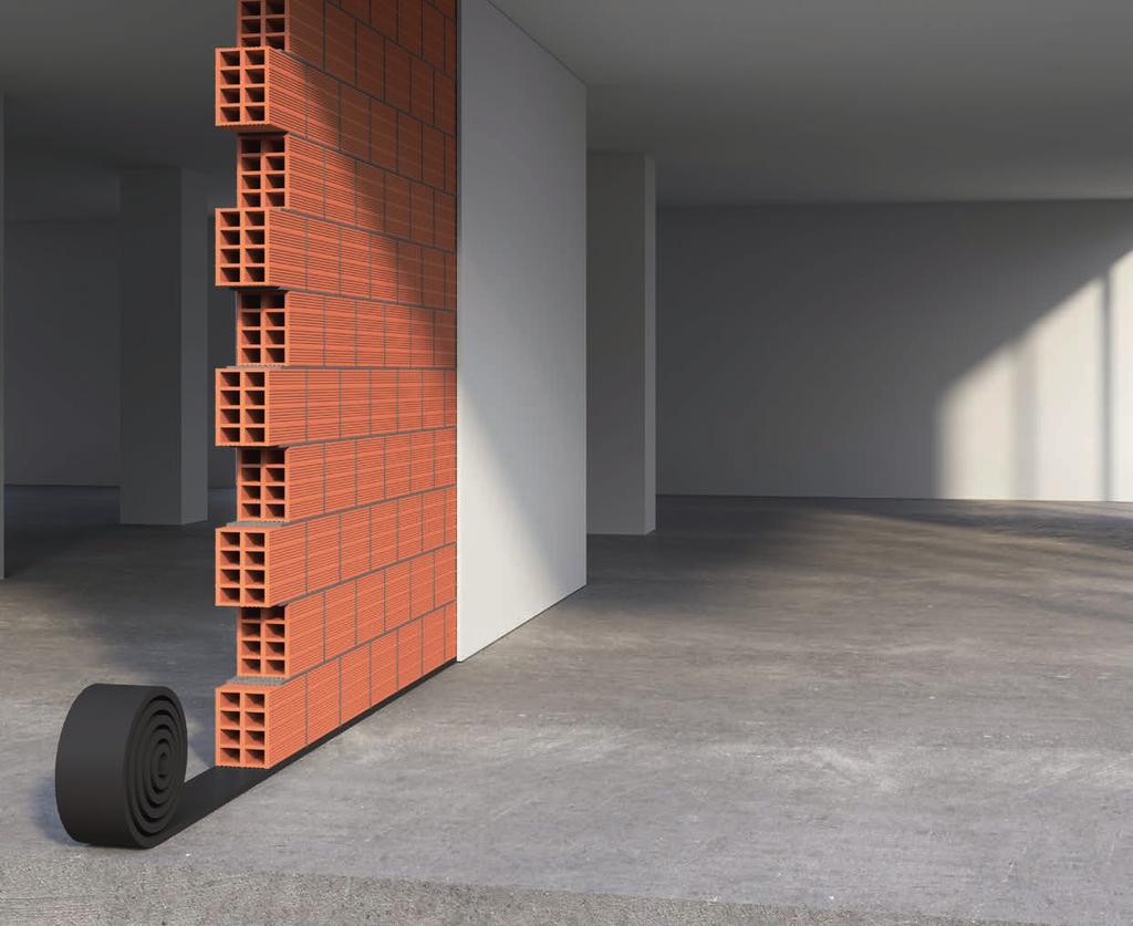
78 76

79 MS-RO Material Data Sheet CORK & RECYCLED RUBBER MS-R0 - a Wall Bearing material - is part of the Amorim Cork Composites range and it represents an excellent solution for acoustical and vibration issues. MS-R0 is manufactured from recycled rubber and granulate cork and it has been developed to effectively interrupt the transmission of footstep noise vertically through the masonry. If wall bearings are used consistently throughout a building, and other sound transmission vectors are eliminated, this can significantly improve the quality of living conditions. The product is suitable for acoustic insulation in loadbearing and non-load-bearing walls. LOAD RANGE WORKLOAD MAXIMUM LOAD 0,3-1,4* MPa (43,5-3* psi) 8 MPa (1160 psi)** E-MODULE Elastic Modulus [MPa] ELASTIC MODULUS [MPa] 30,0 25,0 15,0 10,0 5,0 0,0 0,00 0, 0,40 0,60 0,80 1,00 1,40 E(Static) 10mm E(Dyn) 10mm 5Hz E(Dyn) 10mm 10Hz E(Dyn) 10mm 40Hz E(Static) 5mm E(Dyn) 5mm 5Hz E(Dyn) 5mm 10Hz E(Dyn) 5mm 40Hz STATIC (1) 3,6-9 MPa (522, psi) DYNAMIC (2) 6,5-28,0 MPa (942, ,06 psi) _ (1) DIN (ADAPTED) - TANGENTIAL MODULUS (2) DIN (ADAPTED) - DEPENDING ON LOAD AND FREQUENCY * AT 25% DEFLECTION ** AT <50% DEFLECTION Compression Set (%) (1) <15 Tensile Strength (MPa) (2) >0,6 (>87psi) Elongation at break (%) (2) >15 Density (kg/m³) (3) 600 (40lb/ft³) Shore Hardness (Shore A) (4) Natural Frequency (Hz) for 10mm thickness 21,5* Natural Frequency (Hz) for 5mm thickness 26,5* Dynamic Stiffness [N/mm 3 ] DYNAMIC STIFFNESS [N/mm 3 ] 3,50 3,00 2,50 2,00 1,50 1,00 0,50 0,00 0,00 0, 0,40 0,60 0,80 1,00 1, 1,40 K(Stat) 10mm K(Dyn) 10mm 5Hz K(Dyn) 10mm 10Hz K(Dyn) 10mm 40Hz K(Stat) 5 mm K(Dyn) 5mm 5Hz K(Dyn) 5mm 10Hz K(Dyn) 5mm 40Hz (1) DIN MEASURED 30MIN AFTER DECOMPRESSION WITH 50% DEFORMATION / 23ºC AFTER 72H (2) DIN (3) ASTM D97 (4) ASTM D 2240 *AT 1,4MPa STRESS ADVANTAGES High resistance to compression Low dynamic stiffness Resistance to contact with liquids Sustainable and recyclable WALL BEARING 04 77
80 STANDARD DIMENSIONS Standard Dimensions* 10m x 5cm x 10mm or 5mm block flanking high load bearing capacity low termal conductibility 10m x 10cm x 10mm or 5mm 10m x 15cm x 10mm or 5mm 10m x cm x 10mm or 5mm stable creep behavior BENEFITS lasting elasticy * Other dimensions available. easy to cut PHYSICAL AND MECHANICAL PROPERTIES LOAD DEFLECTION 9,0 CREEP 0,7MPa (% OF START HEIGHT) 10% 8,0 7,0 8% 6,0 Load [MPa] 5,0 4,0 3,0 6% 4% 2,0 2% 1,0 0,0 0,0 0,5 1,0 1,5 2,0 2,5 3,0 3,5 4,0 4,5 5,0 Deflection [mm] 10mm Time [h] INSTALLATION Before the MS-R0 wall bearing is installed, check the floor for surface irregularities. If it is uneven (with projections, surface roughness or similar), apply a smooth mortar layer; After the surface layer has been allowed to dry, lay the wall bearing. Make sure that it projects by approx. 15mm on the side on which the wall is to be plastered; Sections of wall bearing are butt-jointed together, and the joint secured with adhesive tape for concrete. The data provided in this Material Data Sheet represents typical values. This information is not intended to be used as a purchasing specification and does not imply suitability for use in a specific application. Failure to select the proper product may result in either equipments damage or personal injury. Please contact Amorim Cork Composites regarding specific application recommendations. Amorim Cork Composites expressly disclaims all warranties, including any implied warranties or merchantability or of fitness for a particular purpose. Amorim Cork Composites is not liable for any indirect special, incidental, consequential, or punitive damages as a result of using the information listed in this MDS. Any of its material specification sheets, its products or any future use or re-use of them by any person or entity. For contractual purposes, please request our Product Specifications Sheet (PDA) ACC Feb 17 EN
81 MS-R1 Material Data Sheet RECYCLED RUBBER MS-R1 - a Wall Bearing material - is part of the Amorim Cork Composites range and it represents an excellent solution for acoustical and vibration issues. MS-R1 is manufactured from recycled rubber granulate and it has been developed to effectively interrupt the transmission of footstep noise vertically through the masonry. If wall bearings are used consistently throughout a building, and other sound transmission vectors are eliminated, this can significantly improve the quality of living conditions. The product is suitable for acoustic insulation in loadbearing and non-load-bearing walls. LOAD RANGE WORKLOAD MAXIMUM LOAD 0,2-0,8* MPa (29-116* psi) 8 MPa (1160 psi)** E-MODULE ELASTIC MODULUS [MPa],0 16,0 STATIC (1) DYNAMIC (2) 3,00-8,00 MPa ( psi) 5,50-18,0 MPa ( psi) _ (1) DIN (ADAPTED) - TANGENTIAL MODULUS (2) DIN (ADAPTED) - DEPENDING ON LOAD AND FREQUENCY * AT 25% DEFLECTION ** AT <50% DEFLECTION Elastic Modulus [MPa] 12,0 8,0 4,0 E(Static) 10mm E(Dyn) 10mm 5Hz E(Dyn) 10mm 10Hz Compression Set (%) (1) 4,3 Tensile Strength (MPa) (2) > 0,5 (73 psi) Elongation at break (%) (1) > 75 Density (kg/m³) (3) 750 (47lb/ft³) Shore Hardness (Shore A) (4 ) Dynamic Stiffness [N/mm 3 ] 0,0 0,00 0, 0,40 1,80 1,60 1,40 1, 1,00 0,80 0,60 0,40 0, DYNAMIC STIFFNESS [N/mm 3 ] 0,00 0, 0,40 0,60 0,80 0,60 0,80 E(Dyn) 10mm 40Hz K(Stat) 10mm K(Dyn) 10mm 5Hz K(Dyn) 10mm 10Hz K(Dyn) 10mm 40Hz Flammability (5) *B2 Natural Frequency (Hz) ** (1) DIN MEASURED 30MIN AFTER DECOMPRESSION WITH 50% DEFORMATION / 23ºC AFTER 72H (2) DIN (3) ASTM D297 (4) ASTM D2240 (5) DIN 4102 * B2 = NORMAL FLAMMABLE **AT 0,8MPa STRESS (10MM THICKNESS) ADVANTAGES High resistance to compression Low dynamic stiffness Resistance to contact with liquids Sustainable and recyclable WALL BEARING 04 79
82 STANDARD DIMENSIONS Standard Dimensions* 10m x 5cm x 10mm or 5mm block flanking high load bearing capacity low termal conductibility 10m x 10cm x 10mm or 5mm 10m x 15cm x 10mm or 5mm 10m x cm x 10mm or 5mm stable creep behavior BENEFITS lasting elasticy * Other dimensions available. easy to cut PHYSICAL AND MECHANICAL PROPERTIES LOAD DEFLECTION 9,0 CREEP 0,4MPA (% OF START HEIGHT) 10% 8,0 7,0 8% 6,0 5,0 4,0 3,0 2,0 1,0 0,00 0,0 0,5 1,0 1,5 2,0 2,5 3,0 3,5 4,0 4,5 5,0 Deflection [mm] 10mm 6% 4% 2% Time [h] INSTALLATION Before the MS-R1 wall bearing is installed, check the floor for surface irregularities. If it is uneven (with projections, surface roughness or similar), apply a smooth mortar layer; After the surface layer has been allowed to dry, lay the wall bearing. Make sure that it projects by approx. 15mm on the side on which the wall is to be plastered; Sections of wall bearing are butt-jointed together, and the joint secured with adhesive tape for concrete. The data provided in this Material Data Sheet represents typical values. This information is not intended to be used as a purchasing specification and does not imply suitability for use in a specific application. Failure to select the proper product may result in either equipments damage or personal injury. Please contact Amorim Cork Composites regarding specific application recommendations. Amorim Cork Composites expressly disclaims all warranties, including any implied warranties or merchantability or of fitness for a particular purpose. Amorim Cork Composites is not liable for any indirect special, incidental, consequential, or punitive damages as a result of using the information listed in this MDS. Any of its material specification sheets, its products or any future use or re-use of them by any person or entity. For contractual purposes, please request our Product Specifications Sheet (PDA) ACC Feb 17 EN

83 MS-R2 Material Data Sheet CORK & RECYCLE POLYURETHANE MS-R2 - a Wall Bearing material - is part of the Amorim Cork Composites range and it represents an excellent solution for acoustical and vibration issues. MS-R2 is manufactured from cork and recycled polyurethane granulate and it has been developed to effectively interrupt the transmission of footstep noise vertically through the masonry. If wall bearings are used consistently throughout a building, and other sound transmission vectors are eliminated, this can significantly improve the quality of living conditions. The product is suitable for acoustic insulation in non-loadbearing walls. LOAD RANGE WORKLOAD MAXIMUM LOAD 0,1-0,43* MPa (14,5-62,43* psi) 1,25 MPa (181,3 psi)** E-MODULE Elastic Modulus [MPa] ELASTIC MODULUS [MPa] 14,0 12,0 10,0 8,0 6,0 4,0 2,0 0,0 0,00 0,05 0,10 0,15 0, 0,25 0,30 0,35 0,40 0,45 E(Dyn) 10mm 40Hz E(Dyn) 10mm 10Hz E(Dyn) 5mm 4Hz E(Dyn) 10mm 5Hz E(Dyn) 5mm 10Hz E(Dyn) 5mm 5Hz E(Static) 5mm E(Static) 10mm STATIC (1) 1,38-2,30MPa (0,15-333,59 psi) DYNAMIC (2) 3,8-13,0 MPa (551, ,49 psi) (1) DIN (ADAPTED) - TANGENTIAL MODULUS (2) DIN (ADAPTED) - DEPENDING ON LOAD AND FREQUENCY * AT 25% DEFLECTION ** AT <50% DEFLECTION Compression Set (%) (1) 50% Tensile Strength (MPa) (2) >0,1 (>14,5psi) Elongation at break (%) (2) 46% Density (kg/m³) (3) 250 (15,6lb/ft3) Shore Hardness (Shore A) (4) Natural Frequency (Hz) for 10mm thickness 25** Natural Frequency (Hz) for 5mm thickness 31** Dynamic Stiffness [N/mm 3 ] DYNAMIC STIFFNESS [N/mm 3 ] 1,40 1, 1,00 0,80 0,60 0,40 0, 0,00 0,00 0,05 0,10 0,15 0, 0,25 0,30 0,35 0,40 0,45 K(Dyn) 5mm 5Hz K(Dyn) 5mm 10Hz K(Dyn) 5mm 5Hz K(Dyn) 10mm 40Hz K(Dyn) 10mm 10Hz K(Dyn) 10mm 5Hz K(Stat) 5mm K(Stat) 10mm (1) DIN MEASURED 30MIN AFTER DECOMPRESSION WITH 50% DEFORMATION / 23ºC AFTER 70H (2) DIN (3) ASTM D297 (4) ASTM D 2240 **AT 0,43MPa STRESS ADVANTAGES High resistance to compression Low dynamic stiffness Resistance to contact with liquids Sustainable and recyclable WALL BEARING 04 81

84 STANDARD DIMENSIONS Standard Dimensions* 10m x 5cm x 10mm or 5mm block flanking high load bearing capacity low termal conductibility 10m x 10cm x 10mm or 5mm 10m x 15cm x 10mm or 5mm 10m x cm x 10mm or 5mm stable creep behavior BENEFITS lasting elasticy * Other dimensions available. easy to cut PHYSICAL AND MECHANICAL PROPERTIES LOAD DEFLECTION 1.4 CREEP 0,215MPa (% OF START HEIGHT) 10% % Load [MPa] 0,8 0,6 0,4 0,2 6% 4% 2% 0,0 0,0 0,5 1,0 1,5 2,0 2,5 3,0 3,5 4,0 4,5 5,0 Deflection [mm] 10mm Time [h] INSTALLATION Before the MS-R2 wall bearing is installed, check the floor for surface irregularities. If it is uneven (with projections, surface roughness or similar), apply a smooth mortar layer; After the surface layer has been allowed to dry, lay the wall bearing. Make sure that it projects by approx. 15mm on the side on which the wall is to be plastered; Sections of wall bearing are butt-jointed together, and the joint secured with adhesive tape for concrete. The data provided in this Material Data Sheet represents typical values. This information is not intended to be used as a purchasing specification and does not imply suitability for use in a specific application. Failure to select the proper product may result in either equipments damage or personal injury. Please contact Amorim Cork Composites regarding specific application recommendations. Amorim Cork Composites expressly disclaims all warranties, including any implied warranties or merchantability or of fitness for a particular purpose. Amorim Cork Composites is not liable for any indirect special, incidental, consequential, or punitive damages as a result of using the information listed in this MDS. Any of its material specification sheets, its products or any future use or re-use of them by any person or entity. For contractual purposes, please request our Product Specifications Sheet (PDA) ACC Feb 17 EN
85 NOTES 83
86 NOTES 84
87

88 ACC JUN 17 EN EMEA and AROW AMORIM CORK COMPOSITES Rua de Meladas, P.O. Box Mozelos - VFR Portugal T F E. acc@amorim.com