Stretching NPSHA vs. NPSHR to the Limit
|
|
|
- Evan Hodges
- 5 years ago
- Views:
Transcription

1 Feedwater Systems Reliability Users Group (Jan 2017) Austin, TX Stretching NPSHA vs. NPSHR to the Limit Presenter: Art Washburn P.E.
2 DISCUSSION POINTS Two Rules to Get You Home and Plant Priorities Customer Challenge To Perform Inspections & Maintenance Online Manage In-Leakage to Accomplish Inspections by Creative Means Sump Pump and System NPSHR vs. NPSHA Source References
3 Two Rules:
4 Two Rules: Rule #1 Make Conservative Decisions
5 Two Rules: Rule #1 Make Conservative Decisions Rule #2 Maintain Design Control
6 Two Rules: Rule #1 Make Conservative Decisions Rule #2 Maintain Design Control Plant Priorities:
7 Two Rules: Rule #1 Make Conservative Decisions Rule #2 Maintain Design Control Plant Priorities: 1. Nuclear Safety
8 Two Rules: Rule #1 Make Conservative Decisions Rule #2 Maintain Design Control Plant Priorities: 1. Nuclear Safety 2. Legal Requirements
9 Two Rules: Rule #1 Make Conservative Decisions Rule #2 Maintain Design Control Plant Priorities: 1. Nuclear Safety 2. Legal Requirements 3. Efficiency
10 Customer Challenge to Perform Inspections & Maintenance Online - Inspect Circulating Water Inlet Piping, Safety Related - Cross Tie Valve Between Plants Leaks ~750 GPM - Dual Unit Outage Required to Allow Personnel Access to Inspect Piping, Water Box Valves
11 Creative Ideas Needed - Site Planning Dual Unit Outage, Estimated Cost Greater Than $10 Million - Maintenance Organization Identifies Creative Idea to Complete Inspections with 750 GPM In-Leakage - Provide Sump Pump: 1000 X FT of Head

12 Circulating Water Inlet Piping, Water Box, Condenser
13 Inlet Circulating Water Piping Access Point, 30 Manway
14 Sump Pump Predicted Performance Test Curve
15 Net Positive Suction Head Available vs. Required Energy acting on the inlet (suction) side of the pump include: 1. Atmospheric Pressure (positive) 2. Lift (negative) 3. Pump Impeller requirements (negative) 4. Friction losses (negative) In order for the pump to move the water, the Net Positive Suction Head Available (NPSHA) must be greater than the Net Positive Suction Head Required (NPSHR). NPSHA > NPSHR (FT absolute) Atmospheric Pressure > Lift + Impeller Requirement + Friction Losses
16 Net Positive Suction Head Available vs. Required The available suction head (NPSHA) comes from atmospheric pressure acting on the surface of the water. 1 Atmosphere ~ (14.7 PSIA)(2.31 FT/PSI)/(1.0) ~ 33.9 FT abs NPSHA = 33.9 FT abs WATER
17 Net Positive Suction Head Available vs. Required The amount of Lift is elevation differece between the surface of the water and the centerline of the pump impeller. Lift can be either positive or negative depending on the actual configuration in which the pump is running. Sump surface above the pump lift is positive Sump surface below the pump lift is negative Lift = 20.5 ft WATER
18 Net Positive Suction Head Available vs. Required The pump impeller requirements are a function of the flow rate of the individual pump. The higher the flow rate, the greater the NPSH requirement. The NPSH curve the the Oconee Sump Pump is shown below. At maximum expected flow (1000 GPM), NPSHR is approximated to be 8.6 FT abs.
19 Net Positive Suction Head Available vs. Required The friction losses in the pipe were an unknown for this pump. While significant data exists for friction losses in steel pipe, losses in PVC pipe and fittings is not readily available. Also, due to the size of the pipe (6 inch) the flow velocities (12 ft/sec) are much higher than recommended (5 ft/sec). Based on estimates for friction losses, we knew that we would be near the limit of NPSH at the 1,000 gpm flow rate. This is why the actual test was required to determine for certain that the sump pump would perform as required.
20 Net Positive Suction Head Available vs. Required SUMMARY: The final equation for NPSH is as follows: NPSHa > NPSHr Atmospheric Pressure > Lift + Impeller Requirement + Friction Losses 33.9 ft > 20.5 ft ft + Friction Losses 33.9 ft > 29.1 ft + Friction Losses Therefore Friction Losses must be less than 4.8 ft in order for the pump to perform its intended function. What we learned in the first test is that the friction losses in the suction line achieve 4.8 ft when the flow rate goes above approximately 950 gpm. Therefore, any flow rate below this will have sufficient NPSH for the pump to perform its intended function.
21 Test Pit: Maximum Attainable Flowrate at Duplicated Suction Condition
22 Sump Pump: Inadequate NPSHA Performance

23 Foot Valve Head Loss Curve: Simmons 8 Valve
24 Suction Piping: Friction Losses - 6 Sch. 80 Pipe: 1000 GPM, 12.5 FPS, Friction Loss (7.2 FT / 100 FT) / 100 = X / 20, X = 1.44 FT - Limits: - Steel Pipe, 8 12 FPS - PVC Pipe, 5 FPS max (Wear, Noise)
25 Discharge Piping: Friction Losses - 6 Sch. 80 Pipe: 1000 GPM, 12.5 FPS, Friction Loss (7.2 FT / 100 FT) - Unit 3: 7.2 / 100 = X / 500 FT, X = 32.4 FT - Unit 1: 7.2 / 100 = X / 1100 FT, X = 79.2 FT - Limits: - Steel Pipe, 8 12 FPS - PVC Pipe, 5 FPS max (Wear, Noise)
26 Sump Pump Predicted Performance Test Curve

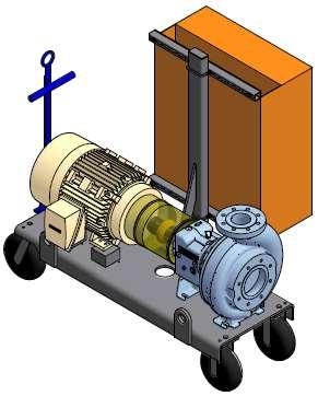
27 Sump Pump Skid Assembly

28 Sump Pump Skid Assembly - Finished
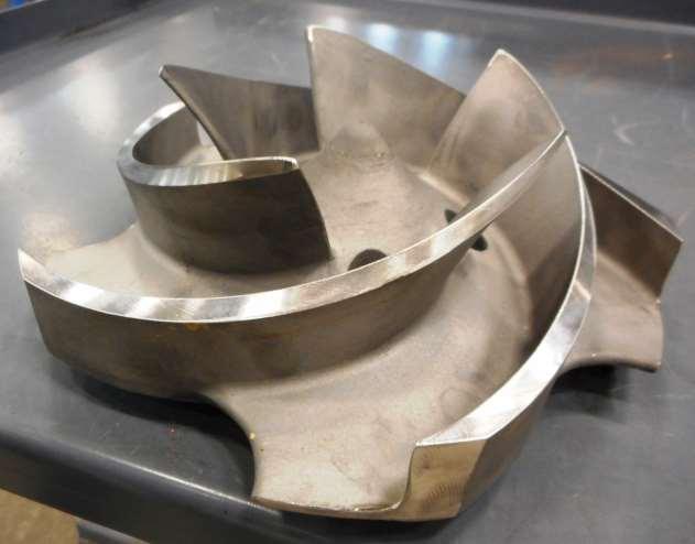
29 Impeller
, and Removal of Suction Piping System Valve Leather")
30 Sump Pump Foot Valve Assembly Sized a Vortex Breaker Plate Plate Diameter Still Fit Thru 30 Access Manway Added Drain Valve to Allow Quick Opening from Outside Pit, Emergent Draining of Water (250 lbs), and Removal of Suction Piping System Valve Leather Flapper

31 Suction Piping

32 Suction Piping Joints, Fittings, Zero Leakage

33 Suction Piping Joints, Fittings, Zero Leakage

34 Test Pit: Suction Piping Mock Up of Field Configuration

35 Test Pit: Suction Piping Mock Up of Field Configuration

36 Test Pit: Suction Piping Mock Up of Field Configuration
37 Test Pit: Maximum Attainable Flowrate at Duplicated Suction Condition
38 Sump Pump: Inadequate NPSHA Performance

39 Field Configuration: - Suction Pipe - Fill & Vent Connects - Manway Cover Positioned for Installation in an Emergency - Limited Access Thru 30 Manway

40 Field Installation: Discharge Piping

41 Unit 1: Pump Flowrate Achieved

42 Field Installation: 30 Manway Access

43 In-Leakage: Dumping Right on Top of Foot Valve

44 In-Leakage: View from Turbine Building Bottom Floor

45 In-Leakage: View from Turbine Building Bottom Floor
46 In-Leakage: Video from Turbine Building Bottom Floor

47 Oconee Unit 3: Sump Pump System Configuration
48 Oconee Unit 3 Inspections: Sump Pump Performance Highlights - Allowed for Inspections of Circulation Water Piping - Unwatering Circulating Water Inlet Piping: X Gallons - Discharge Piping Length of Run: 450 FT - Capacity: 750 GPM In-Leakage, 900 GPM Maximum - Discharge Piping 10 FT Sections: Zero Leakage - 6 Discharge Piping Material: PVC - Discharge Returned Water Back to Lake Keowee

49 Oconee Unit 1: Sump Pump System Configuration
50 Oconee Unit 1 Inspections: Sump Pump Performance Highlights - Allowed for Inspections of Circulation Water Piping, Water Box Valves, and an Amertap System Modification - Unwatering Circulating Water Inlet Piping: 3,542,000 Gallons - Discharge Piping Length of Run: 1,100 FT - Capacity: 400 GPM In-Leakage, 880 GPM Maximum Pumped - Discharge Piping 10 FT Sections: Zero Leakage - 6 Discharge Piping Material Changed from PVC to Aluminum. - Material Change Relieved Fire Watch Requirements, as the Piping is Routed Thru Operating Units (2 & 3). - Discharge Returned Water Back to Lake Keowee - Chemistry Department did not have to Manage 3.5 Million Gallons of Water Thru Chemical Treatment Ponds
51 Oconee Unit 1 Inspections: Pump Lost Prime 3 Times - Pump Prime was Lost One Time as a Result of Low Water Level - Water Wave Generating a Vortex - Scaffold Builder Bumped Dump Valve, Opening Valve
52 SOURCE REFERENCES: Centrifugal Pumps: Design & Application, Lobanoff and Ross (practical application) Centrifugal and Axial Flow Pumps, Stepanoff (theory) Centrifugal Pumps, Gülich Vertical Turbine, Mixed Flow & Propeller Pumps, Dicmus Centrifugal Pump Handbook, Sulzer Pump Handbook, Karassik Centrifugal Pump Clinic, Karassik Centrifugal Pumps Selection & Operation, Karassik Centrifugal Pumps, Karassik

53 Gene Cernan, Last Man on the Moon, Dead at 82 R.I.P.

54 THE (HAPPY) END QUESTIONS?