WAYNE COMMUNITY COLLEGE SECTION
|
|
|
- Rafe McLaughlin
- 5 years ago
- Views:
Transcription
1 WAYNE COMMUNITY COLLEGE SECTION LIST OF DRAWING SHEETS SECTION LIST OF DRAWING SHEETS 1.1 LIST OF DRAWINGS A. Drawings: Drawings consist of the Contract Drawings and other drawings listed on the Table of Contents page of the separately bound drawing set titled Wayne Country Community College District, Eastern Campus Foundation Rehabilitation, dated August 20, 2018 B. List of Drawings: Drawings consist of the following Contract Drawings and other drawings of type indicated: 1. Eastern Regional Center Construction document prepared by Rossetti associates / Architects Planners dated January 3, Exterior / Interior Building Stabilization prepared Hamilton Anderson Associates Inc. & L & A Structural Engineers, Inc. dated March 10, 2003 END OF DOCUMENT LIST OF DRAWING SHEETS
2 WAYNE COUNTY COMMUNITY COLLEGE SECTION: INDEX OF SPECIFICATIONS REQUIREMENTS AND CONDITIONS OF THE CONTRACT SECTION TITLE DIVISION 00 PROCUREMENT FORM & INFORMATION List Of Drawings Geotechnical Data Existing Condition Unit Prices DIVISION 01 GENERAL REQUIREMENTS Quality Requirements Allowances Payment Procedures Project Management and Coordination Construction Progress Documentation Quality Requirements Execution Requirements Cutting and Patching DIVISION 02 - Demolition Selective Demolition. DIVISION 03 CONCRETE Cast-In-Place Concrete DIVISION 04 MASONRY Unit Masonry DIVISION 06 WOODS AND PLASTICS Rough Carpentry DIVISION 7 THERMAL AND MOISTURE PROCTECTION Building Insulation Sheet Metal Flashing and Trim Joint Sealants DIVISION 08 DOORS AND WINDOWS Metal Doors and Frames Hollow Metal
3 WAYNE COUNTY COMMUNITY COLLEGE SECTION: INDEX OF SPECIFICATIONS DIVISION 09 FINISHES Gypsum Board Assemblies Paintings DIVISION 31 -SITE Site Clearing Earthwork Dewatering Drilled Piers and Shafts DIVISION 32- EXTERIOR IMPROVEMENT Landscaping Soil Boring Data
4 WAYNE COUNTY COMMUNITY COLLEGE SECTION EAST CAMPUS GEOTECHNICA DATA DOCUMENT GEOTECHNICAL DATA 1.1 GEOTECHNICAL DATA A. This Document with its referenced attachments is part of the Procurement and Contracting Requirements for Project. They provide Owner's information for Bidders' convenience and are intended to supplement rather than serve in lieu of Bidders' own investigations. They are made available for Bidders' convenience and information but are not a warranty of existing conditions. This Document and its attachments are not part of the Contract Documents. B. Soil-boring data for Project, procured by Femi Talabi Associates, Inc, dated April , is available for viewing as appended to this Document. C. A geotechnical investigation report for Project, prepared by Testing Engineers Inc, dated April 2, 2018, is available for viewing as appended to this Document. D. Related Requirements: 1. Document "Instructions to Bidders" for the Bidder's responsibilities for examination of Project site and existing conditions. 2. Document "Existing Condition Information" for information about existing conditions that is made available to bidders. END OF DOCUMENT GEOTECHNICAL DATA
5 WAYNE COUNTY COMMUNITY COLLEGE SECTION EAST CAMPUS UNIT PRICES DOCUMENT UNIT PRICES FORM 1.1 BID INFORMATION A. Bidder:. B. Prime Contractor: C. Project Name: WCCCD East Campus Structural Rehabilitation. D. Project Location: 5901 Conner Detroit Michigan E. Owner: Wayne County Community College District. F. Owner Project Number: G. Architect: Femi Talabi & Associates Inc. H. Architect Project Number: <Insert Architect Project number>. I. Construction Manager: <Insert name of Construction Manager>. 1.2 BID FORM SUPPLEMENT A. This form is required to be attached to the Bid Form. B. The undersigned Bidder proposes the amounts below be added to or deducted from the Contract Sum on performance and measurement of the individual items of Work and for adjustment of the quantity given in the Unit-Price Allowance for the actual measurement of individual items of the Work. 1.3 UNIT PRICES A. Unit-Price No. 1: Soil Excavation 1. Dollars ($ ) per Cu.Yd. B. Unit-Price No. 2: Caisson Permanent Steel Casings. 1. Dollars ($ ) per Lineal Ft. C. Unit-Price No. 3: Reinforcing Steel and Dowel, installed 1. Dollars ($ ) per Ib. D. Unit-Price No. 4: Remove and Replace Existing Slab on Grade 1. Dollars ($ ) per Cu. Yd. E. Unit-Price No. 5: Remove and Replace Precast Double Tee Flange UNIT PRICES FORM
6 WAYNE COUNTY COMMUNITY COLLEGE SECTION EAST CAMPUS UNIT PRICES 1. Dollars ($ ) per Sq FT. F. Unit-Price No. <Insert unit-price number>: <Insert unit-price item>. 1. Dollars ($ ) per unit. 1.4 SUBMISSION OF BID SUPPLEMENT A. Respectfully submitted this day of, B. Submitted By: (Insert name of bidding firm or corporation). C. Authorized Signature: (Handwritten signature). D. Signed By: (Type or print name). E. Title: (Owner/Partner/President/Vice President). END OF DOCUMENT UNIT PRICES FORM
7 WAYNE COUNTY COMMUNITY COLLEGE SECTION: QUALITY REQUIREMENTS SECTION QUALITY REQUIREMENTS PART 1 - GENERAL 1.1 SUMMARY A. This Section includes administrative and procedural requirements for quality assurance and quality control. B. Testing and inspecting services are required to verify compliance with requirements specified or indicated. These services do not relieve Contractor of responsibility for compliance with the Contract Document requirements. 1. Specified tests, inspections, and related actions do not limit Contractor's quality-control procedures that facilitate compliance with the Contract Document requirements. 2. Requirements for Contractor to provide quality-control services required by Engineer, Owner, or authorities having jurisdiction are not limited by provisions of this Section. 1.2 DEFINITIONS A. Quality-Assurance Services: Activities, actions, and procedures performed before and during execution of the Work to guard against defects and deficiencies and ensure that proposed construction complies with requirements. B. Quality-Control Services: Tests, inspections, procedures, and related actions during and after execution of the Work to evaluate that completed construction complies with requirements. Services do not include contract enforcement activities performed by Architect. C. Testing Agency: An entity engaged to perform specific tests, inspections, or both. Testing laboratory shall mean the same as testing agency. 1.3 SUBMITTALS A. Qualification Data: For testing agencies specified in "Quality Assurance" Article to demonstrate their capabilities and experience. Include proof of qualifications in the form of a recent report on the inspection of the testing agency by a recognized authority. B. Delegated-Design Submittal: In addition to Shop Drawings, Product Data, and other required submittals, submit a statement, signed and sealed by the responsible design professional, for each product and system specifically assigned to Contractor to be designed or certified by a design professional, indicating that the products and systems are in compliance with performance and design criteria indicated. Include list of codes, loads, and other factors used in performing these services. C. Permits, Licenses, and Certificates: For Owner's records, submit copies of permits, licenses, certifications, inspection reports, releases, jurisdictional settlements, notices, receipts for fee QUALITY REQUIREMENTS
8 WAYNE COUNTY COMMUNITY COLLEGE SECTION: QUALITY REQUIREMENTS payments, judgments, correspondence, records, and similar documents, established for compliance with standards and regulations bearing on performance of the Work. 1.4 QUALITY ASSURANCE A. Fabricator Qualifications: A firm experienced in producing products similar to those indicated for this Project and with a record of successful in-service performance, as well as sufficient production capacity to produce required units. B. Factory-Authorized Service Representative Qualifications: An authorized representative of manufacturer who is trained and approved by manufacturer to inspect installation of manufacturer's products that are similar in material, design, and extent to those indicated for this Project. C. Installer Qualifications: A firm or individual experienced in installing, erecting, or assembling work similar in material, design, and extent to that indicated for this Project, whose work has resulted in construction with a record of successful in-service performance. D. Manufacturer Qualifications: A firm experienced in manufacturing products or systems similar to those indicated for this Project and with a record of successful in-service performance. E. Professional Engineer Qualifications: A professional engineer who is legally qualified to practice in jurisdiction where Project is located and who is experienced in providing engineering services of the kind indicated. Engineering services are defined as those performed for installations of the system, assembly, or product that are similar to those indicated for this Project in material, design, and extent. F. Retain paragraph and subparagraph below if other Specification Sections assign certain items of work to preselected contractors (specialists). Revise to suit Project. See Evaluations about naming parties other than Owner and Contractor in Specifications.. G. Testing Agency Qualifications: An agency with the experience and capability to conduct testing and inspecting indicated, as documented by ASTM E 548, and that specializes in types of tests and inspections to be performed. 1.5 UQALITY CONTROL A. Contractor Responsibilities: Unless otherwise indicated, provide quality-control services specified and required by authorities having jurisdiction. 1. Where services are indicated as Contractor's responsibility, engage a qualified testing agency to perform these quality-control services. 2. Where quality-control services are indicated as Contractor's responsibility, submit a certified written report, in duplicate, of each quality-control service. QUALITY REQUIREMENTS
9 WAYNE COUNTY COMMUNITY COLLEGE SECTION: QUALITY REQUIREMENTS B. Manufacturer's Field Services: Where indicated, engage a factory-authorized service representative to inspect field-assembled components and equipment installation, including service connections. Report results in writing. C. Coordination: Coordinate sequence of activities to accommodate required quality-assurance and quality-control services with a minimum of delay and to avoid necessity of removing and replacing construction to accommodate testing and inspecting. 1. Schedule times for tests, inspections, obtaining samples, and similar activities. PART 2 - PRODUCTS (Not Used) PART 3 - EXECUTION 3.1 REPAIR AND PROTECTION A. General: On completion of testing, inspecting, sample taking, and similar services, repair damaged construction and restore substrates and finishes. 1. Provide materials and comply with installation requirements specified in other Sections of these Specifications. Restore patched areas and extend restoration into adjoining areas in a manner that eliminates evidence of patching. 2. Comply with the Contract Document requirements for Division 1 Section "Cutting and Patching." B. Protect construction exposed by or for quality-control service activities. C. Repair and protection are Contractor's responsibility, regardless of the assignment of responsibility for quality-control services. END OF SECTION QUALITY REQUIREMENTS
10 WAYNE COUNTY COMMUNITY COLLEGE SECTION: ALLOWANCES SECTION ALLOWANCES PART 1 - GENERAL 1.1 RELATED DOCUMENTS A. Drawings and general provisions of the Contract, including General and Supplementary Conditions and other Division 1 Specification Sections, apply to this Section. 1.2 SUMMARY A. This Section includes administrative and procedural requirements governing allowances. 1. Certain materials and equipment are specified in the Contract Documents by allowances. In some cases, these allowances include installation. Allowances have been established in lieu of additional requirements and to defer selection of actual materials and equipment to a later date when additional information is available for evaluation. If necessary, additional requirements will be issued by Change Order.. B. Types of allowances include the following: 1. Contingency allowances C. Related Sections include the following Division 1 Sections below contain requirements that relate directly to allowances. 1. Division 1 Section "Unit Prices" for procedures for using unit prices. 2. Division 1 Section "Quality Requirements" for procedures governing the use of allowances for testing and inspecting. 1.3 SELECTION AND PURCHASE A. At the earliest practical date after award of the Contract, advise Architect of the date when final selection and purchase of each product or system described by an allowance must be completed to avoid delaying the Work. 1.4 SUBMITTALS A. Submit proposals for purchase of products or systems included in allowances, in the form specified for Change Orders. B. Submit invoices or delivery slips to show actual quantities of materials delivered to the site for use in fulfillment of each allowance. ALLOWANCES
11 WAYNE COUNTY COMMUNITY COLLEGE SECTION: ALLOWANCES 1.5 CONTINGENCY ALLOWANCES A. Use the contingency allowance only as directed by Engineer for Owner's purposes and only by Change Orders that indicate amounts to be charged to the allowance. B. Change Orders authorizing use of funds from the contingency allowance will include Contractor's related costs and reasonable overhead and profit margins. C. At Project closeout, credit unused amounts remaining in the contingency allowance to Owner by Change Order. PART 2 - PRODUCTS (Not Used) PART 3 - EXECUTION 3.1 EXAMINATION A. Examine products covered by an allowance promptly on delivery for damage or defects. Return damaged or defective products to manufacturer for replacement. 3.2 PREPARATION A. Coordinate materials and their installation for each allowance with related materials and installations to ensure that each allowance item is completely integrated and interfaced with related work. 3.3 SCHEDULE OF ALLOWANCES A. Allowance No. <Insert Number>: Include <Insert allowance description> as specified in Division <Insert Division number> Section "<Insert Section title>" [and as shown on Drawings]. END OF SECTION ALLOWANCES
12 WANYE COUNTY COMMUNITY COLLEGE SECTION: PAYMENT PROCEDURES SECTION PAYMENT PROCEDURES PART 1 - GENERAL 1.1 RELATED DOCUMENTS A. Drawings and general provisions of the Contract, including General and Supplementary Conditions and other Division 01 Specification Sections, apply to this Section. 1.2 SUMMARY A. This Section specifies administrative and procedural requirements necessary to prepare and process Applications for Payment. B. Related Sections include the following:. 1. Division 01 Section "Unit Prices" for administrative requirements governing use of unit prices.. 2. Division 01 Section "Construction Progress Documentation" for administrative requirements governing preparation and submittal of Contractor's Construction Schedule and Submittals Schedule. 1.3 DEFINITIONS A. Schedule of Values: A statement furnished by Contractor allocating portions of the Contract Sum to various portions of the Work and used as the basis for reviewing Contractor's Applications for Payment. 1.4 SCHEDULE OF VALUES A. Coordination: Coordinate preparation of the Schedule of Values with preparation of Contractor's Construction Schedule. 1. Correlate line items in the Schedule of Values with other required administrative forms and schedules, including the following: a. Application for Payment forms with Continuation Sheets. b. Submittals Schedule. 2. Submit the Schedule of Values to Engineer [through Construction Manager] at earliest possible date but no later than [seven] days before the date scheduled for submittal of initial Applications for Payment. PAYMENT PROCEDURES
13 WANYE COUNTY COMMUNITY COLLEGE SECTION: PAYMENT PROCEDURES B. Format and Content: Use the Project Manual table of contents as a guide to establish line items for the Schedule of Values. Provide at least one line item for each Specification Section. 1. Identification: Include the following Project identification on the Schedule of Values: a. Project name and location. b. Name of Engineer. c. Engineer's project number. d. Contractor's name and address. e. Date of submittal. 2. Arrange the Schedule of Values in tabular form with separate columns to indicate the following for each item listed: a. Related Specification Section or Division. b. Description of the Work. c. Name of subcontractor. d. Name of manufacturer or fabricator. e. Name of supplier. f. Change Orders (numbers) that affect value. g. Dollar value. 1) Percentage of the Contract Sum to nearest one-hundredth percent, adjusted to total 100 percent. 3. Provide a breakdown of the Contract Sum in enough detail to facilitate continued evaluation of Applications for Payment and progress reports. Coordinate with the Project Manual table of contents. Provide several line items for principal subcontract amounts, where appropriate. 4. Round amounts to nearest whole dollar; total shall equal the Contract Sum. 5. Provide a separate line item in the Schedule of Values for each part of the Work where Applications for Payment may include materials or equipment purchased or fabricated and stored, but not yet installed. a. Differentiate between items stored on-site and items stored off-site. Include evidence of insurance or bonded warehousing if required. 6. Provide separate line items in the Schedule of Values for initial cost of materials, for each subsequent stage of completion, and for total installed value of that part of the Work. 7. Allowances: Provide a separate line item in the Schedule of Values for each allowance. Show line-item value of unit-cost allowances, as a product of the unit cost, multiplied by measured quantity. Use information indicated in the Contract Documents to determine quantities. 8. Each item in the Schedule of Values and Applications for Payment shall be complete. Include total cost and proportionate share of general overhead and profit for each item. 9. Schedule Updating: Update and resubmit the Schedule of Values before the next Applications for Payment when Change Orders or Construction Change Directives result in a change in the Contract Sum. PAYMENT PROCEDURES
14 WANYE COUNTY COMMUNITY COLLEGE SECTION: PAYMENT PROCEDURES 1.5 APPLICATIONS FOR PAYMENT A. Each Application for Payment shall be consistent with previous applications and payments as certified by Engineer, Construction Manager and paid for by Owner. 1. Initial Application for Payment, Application for Payment at time of Substantial Completion, and final Application for Payment involve additional requirements. B. Payment Application Times: The date for each progress payment is indicated in the Agreement between Owner and Contractor. The period of construction Work covered by each Application for Payment is the period indicated in the Agreement. C. Payment Application Times: The date for each progress payment is the [15th] day of each month. The period covered by each Application for Payment starts on the day following the end of the preceding period and ends [15] days before the date for each progress payment. D. Payment Application Forms: Use [AIA Document G702 and AIA Document G703 Continuation Sheets as form for Applications for Payment. E. Payment Application Forms: Use forms provided by Owner for Applications for Payment. Sample copies are included at end of this Section. F. Application Preparation: Complete every entry on form. Notarize and execute by a person authorized to sign legal documents on behalf of Contractor. Construction Manager will return incomplete applications without action. 1. Entries shall match data on the Schedule of Values and Contractor's Construction Schedule. Use updated schedules if revisions were made. 2. Include amounts of Change Orders and Construction Change Directives issued before last day of construction period covered by application. G. Transmittal: Submit [3] signed and notarized original copies of each Application for Payment to Construction Manager by a method ensuring receipt within 24 hours. One copy shall include waivers of lien and similar attachments if required. 1. Transmit each copy with a transmittal form listing attachments and recording appropriate information about application. H. Waivers of Mechanic's Lien: With each Application for Payment, submit waivers of mechanic's lien from every entity who is lawfully entitled to file a mechanic's lien arising out of the Contract and related to the Work covered by the payment. I. Waivers of Mechanic's Lien: With each Application for Payment, submit waivers of mechanic's liens from subcontractors, sub-subcontractors, and suppliers for construction period covered by the previous application.. 1. When an application shows completion of an item, submit final or full waivers. 2. Owner reserves the right to designate which entities involved in the Work must submit waivers. PAYMENT PROCEDURES
15 WANYE COUNTY COMMUNITY COLLEGE SECTION: PAYMENT PROCEDURES 3. Waiver Delays: Submit each Application for Payment with Contractor's waiver of mechanic's lien for construction period covered by the application. a. Submit final Application for Payment with or preceded by final waivers from every entity involved with performance of the Work covered by the application who is lawfully entitled to a lien. 4. Waiver Forms: Submit waivers of lien on forms, executed in a manner acceptable to Owner. J. Initial Application for Payment: Administrative actions and submittals that must precede or coincide with submittal of first Application for Payment include the following: 1. List of subcontractors. 2. Schedule of Values. 3. Contractor's Construction Schedule (preliminary if not final). 4. Products list. 5. Schedule of unit prices. 6. Submittals Schedule (preliminary if not final). 7. List of Contractor's staff assignments. 8. List of Contractor's principal consultants. 9. Copies of building permits. 10. Copies of authorizations and licenses from authorities having jurisdiction for performance of the Work. 11. Initial progress report. 12. Report of preconstruction conference. 13. Certificates of insurance and insurance policies. 14. Performance and payment bonds. 15. Data needed to acquire Owner's insurance. 16. Initial settlement survey and damage report if required. K. Application for Payment at Substantial Completion: After issuing the Certificate of Substantial Completion, submit an Application for Payment showing 100 percent completion for portion of the Work claimed as substantially complete. 1. Include documentation supporting claim that the Work is substantially complete and a statement showing an accounting of changes to the Contract Sum. 2. This application shall reflect Certificates of Partial Substantial Completion issued previously for Owner occupancy of designated portions of the Work. L. Final Payment Application: Submit final Application for Payment with releases and supporting documentation not previously submitted and accepted, including, but not limited, to the following: 1. Evidence of completion of Project closeout requirements. 2. Insurance certificates for products and completed operations where required and proof that taxes, fees, and similar obligations were paid. 3. Updated final statement, accounting for final changes to the Contract Sum. 4. AIA Document G706, "Contractor's Affidavit of Payment of Debts and Claims." 5. AIA Document G706A, "Contractor's Affidavit of Release of Liens." 6. AIA Document G707, "Consent of Surety to Final Payment." PAYMENT PROCEDURES
16 WANYE COUNTY COMMUNITY COLLEGE SECTION: PAYMENT PROCEDURES 7. Evidence that claims have been settled. 8. Final, liquidated damages settlement statement. PART 2 - PRODUCTS (Not Used) PART 3 - EXECUTION (Not Used) END OF SECTION PAYMENT PROCEDURES
17 WAYNE COUNTY COMMUNITY SECTION: PROJECT MANAGEMENT AND COORDINATION SECTION PROJECT MANAGEMENT AND COORDINATION PART 1 - GENERAL 1.1 SUMMARY A. This Section includes administrative provisions for coordinating construction operations on Project including, but not limited to, the following: 1. General Project coordination procedures. 2. Coordination Drawings. 3. Project meetings. B. See Division 1 Section "Execution Requirements" for procedures for coordinating general installation and field-engineering services, including establishment of benchmarks and control points. 1.2 COORDINATION A. Coordination: Coordinate construction operations included in various Sections of the Specifications to ensure efficient and orderly installation of each part of the Work. Coordinate construction operations, included in different Sections, that depend on each other for proper installation, connection, and operation. 1. Schedule construction operations in sequence required to obtain the best results where installation of one part of the Work depends on installation of other components, before or after its own installation. 2. Coordinate installation of different components with other contractors to ensure maximum accessibility for required maintenance, service, and repair. 3. Make adequate provisions to accommodate items scheduled for later installation. B. Administrative Procedures: Coordinate scheduling and timing of required administrative procedures with other construction activities and activities of other contractors to avoid conflicts and to ensure orderly progress of the Work. Such administrative activities include, but are not limited to, the following: 1. Preparation of Contractor's Construction Schedule. 2. Preparation of the Schedule of Values. 3. Installation and removal of temporary facilities and controls. 4. Delivery and processing of submittals. 5. Progress meetings. 6. Preinstallation conferences. 7. Project closeout activities.. PROJECT MANAGEMENT AND COORDINATION
18 WAYNE COUNTY COMMUNITY SECTION: PROJECT MANAGEMENT AND COORDINATION 1.3 PROJECT MEETINGS A. General: Schedule and conduct meetings and conferences at Engineer s office. 1. Attendees: Inform participants and others involved, and individuals whose presence is required, of date and time of each meeting. Notify Owner and Architect of scheduled meeting dates and times. 2. Agenda: Prepare the meeting agenda. Distribute the agenda to all invited attendees. 3. Minutes: Record significant discussions and agreements achieved. Distribute the meeting minutes to everyone concerned, including Owner and Engineer and Construction Manager, within [3] days of the meeting. B. Preconstruction Conference: Schedule a preconstruction conference before starting construction, at a time convenient to Owner and Engineer, but no later than [15] days after execution of the Agreement. Hold the conference at Project site or another convenient location. Conduct the meeting to review responsibilities and personnel assignments. 1. Attendees: Authorized representatives of Owner, Engineer, and Construction Manager; Contractor and its superintendent; major subcontractors; manufacturers; suppliers; and other concerned parties shall attend the conference. All participants at the conference shall be familiar with Project and authorized to conclude matters relating to the Work. 2. Agenda: Discuss items of significance that could affect progress, including the following: a. Tentative construction schedule. b. Phasing. c. Critical work sequencing. d. Designation of responsible personnel. e. Procedures for processing field decisions and Change Orders. f. Procedures for processing Applications for Payment. g. Distribution of the Contract Documents. h. Submittal procedures. i. Preparation of Record Documents. j. Use of the premises. k. Responsibility for temporary facilities and controls. l. Parking availability. m. Office, work, and storage areas. n. Equipment deliveries and priorities. o. First aid. p. Security. q. Progress cleaning. r. Working hours. C. Preinstallation Conferences: Conduct a preinstallation conference at Project site before each construction activity that requires coordination with other construction. 1. Attendees: Installer and representatives of manufacturers and fabricators involved in or affected by the installation and its coordination or integration with other materials and installations that have preceded or will follow, shall attend the meeting. Advise Engineer and Construction Manager of scheduled meeting dates. PROJECT MANAGEMENT AND COORDINATION
19 WAYNE COUNTY COMMUNITY SECTION: PROJECT MANAGEMENT AND COORDINATION 2. Agenda: Review progress of other construction activities and preparations for the particular activity under consideration, including requirements for the following: a. Contract Documents. b. Options. c. Related Change Orders. d. Purchases. e. Deliveries. f. Submittals. g. Review of mockups. h. Possible conflicts. i. Compatibility problems. j. Time schedules. k. Weather limitations. l. Manufacturer's written recommendations. m. Warranty requirements. n. Compatibility of materials. o. Acceptability of substrates. p. Temporary facilities and controls. q. Space and access limitations. r. Regulations of authorities having jurisdiction. s. Testing and inspecting requirements. t. Required performance results. u. Protection of construction and personnel. 3. Record significant conference discussions, agreements, and disagreements. 4. Do not proceed with installation if the conference cannot be successfully concluded. Initiate whatever actions are necessary to resolve impediments to performance of the Work and reconvene the conference at earliest feasible date. D. Progress Meetings: Conduct progress meetings at [biweekly] intervals. Coordinate dates of meetings with preparation of payment requests. 1. Attendees: In addition to representatives of Owner, Engineer, Construction Manager contractor, subcontractor and supplier. 2. Agenda: Review and correct or approve minutes of previous progress meeting. Review other items of significance that could affect progress. Include topics for discussion as appropriate to status of Project. a. Contractor's Construction Schedule: Review progress since the last meeting. Determine whether each activity is on time, ahead of schedule, or behind schedule, in relation to Contractor's Construction Schedule. Determine how construction behind schedule will be expedited; secure commitments from parties involved to do so. Discuss whether schedule revisions are required to ensure that current and subsequent activities will be completed within the Contract Time. b. Review present and future needs of each entity present, including the following: 1) Interface requirements. 2) Sequence of operations. 3) Status of submittals. 4) Deliveries. PROJECT MANAGEMENT AND COORDINATION
20 WAYNE COUNTY COMMUNITY SECTION: PROJECT MANAGEMENT AND COORDINATION 5) Off-site fabrication. 6) Access. 7) Site utilization. 8) Temporary facilities and controls. 9) Work hours. 10) Hazards and risks. 11) Progress cleaning. 12) Quality and work standards. 13) Change Orders. 14) Documentation of information for payment requests. 3. Reporting: Distribute minutes of the meeting to each party present and to parties who should have been present. Include a brief summary, in narrative form, of progress since the previous meeting and report. a. Schedule Updating: Revise Contractor's Construction Schedule after each progress meeting where revisions to the schedule have been made or recognized. Issue revised schedule concurrently with the report of each meeting. PART 2 - PRODUCTS (Not Used) PART 3 - EXECUTION (Not Used) END OF SECTION PROJECT MANAGEMENT AND COORDINATION
21 WAYNE COUNTY COMMUNITY COLLEGE SECTION: CONSTRUCTION PROGRESS DOCUMENTATION SECTION CONSTRUCTION PROGRESS DOCUMENTATION PART 1 - GENERAL 1.1 SUMMARY A. This Section includes administrative and procedural requirements for documenting the progress of construction during performance of the Work, including the following: 1. Contractor's Construction Schedule. 2. Submittals Schedule. 3. Daily construction reports. 4. Field condition reports.. B. See Division 1 Section "Payment Procedures" for submitting the Schedule of Values. 1.2 SUBMITTALS A. Submittals Schedule: Submit [three] copies of schedule. Arrange the following information in a tabular format: 1. Scheduled date for first submittal. 2. Specification Section number and title. 3. Submittal category (action or informational). 4. Name of subcontractor. 5. Description of the Work covered. 6. Scheduled date for Engineeer's final release or approval. B. Contractor's Construction Schedule: Submit [three] printed copies of initial schedule, one a reproducible print and one a blue- or black-line print, large enough to show entire schedule for entire construction period. C. CPM Reports: Concurrent with CPM schedule, submit [three] printed copies of each of the following computer-generated reports. Format for each activity in reports shall contain activity number, activity description, original duration, remaining duration, early start date, early finish date, late start date, late finish date, and total float. 1. Activity Report: List of all activities sorted by activity number and then early start date, or actual start date if known. 2. Logic Report: List of preceding and succeeding activities for all activities, sorted in ascending order by activity number and then early start date, or actual start date if known. 3. Total Float Report: List of all activities sorted in ascending order of total float. D. Daily Construction Reports: Submit [three] copies at [weekly] intervals. E. Field Condition Reports: Submit [three] copies at time of discovery of differing conditions. CONSTRUCTION PROGRESS DOCUMENTATION
22 WAYNE COUNTY COMMUNITY COLLEGE SECTION: CONSTRUCTION PROGRESS DOCUMENTATION 1.3 COORDINATION A. Coordinate preparation and processing of schedules and reports with performance of construction activities and with scheduling and reporting of separate contractors. B. Coordinate Contractor's Construction Schedule with the Schedule of Values, list of subcontracts, Submittals Schedule, progress reports, payment requests, and other required schedules and reports. 1. Secure time commitments for performing critical elements of the Work from parties involved. 2. Coordinate each construction activity in the network with other activities and schedule them in proper sequence. C. Auxiliary Services: Cooperate with photographer and provide auxiliary services requested, including access to Project site and use of temporary facilities including temporary lighting. PART 2 - PRODUCTS 2.1 SUBMITTALS SCHEDULE A. Preparation: Submit a schedule of submittals, arranged in chronological order by dates required by construction schedule. Include time required for review, resubmittal, ordering, manufacturing, fabrication, and delivery when establishing dates. 1. Coordinate Submittals Schedule with list of subcontracts, the Schedule of Values, and Contractor's Construction Schedule. 2. Submit concurrently with the first complete submittal of Contractor's Construction Schedule. 2.2 CONTRACTOR'S CONSTRUCTION SCHEDULE, GENERAL A. Time Frame: Extend schedule from date established for [the Notice of Award] to date of ] [Final] Completion. 1. Contract completion date shall not be changed by submission of a schedule that shows an early completion date, unless specifically authorized by Change Order. 2. Submittal Review Time: Include review and resubmittal times indicated in Division 1 Section "Submittal Procedures" in schedule. Coordinate submittal review times in Contractor's Construction Schedule with Submittals Schedule. 3. Substantial Completion: Indicate completion in advance of date established for Substantial Completion, and allow time for Engineer's administrative procedures necessary for certification of Substantial Completion. B. Constraints: Include constraints and work restrictions indicated in the Contract Documents and as follows in schedule, and show how the sequence of the Work is affected. 1. Phasing: Arrange list of activities on schedule by phase. CONSTRUCTION PROGRESS DOCUMENTATION
23 WAYNE COUNTY COMMUNITY COLLEGE SECTION: CONSTRUCTION PROGRESS DOCUMENTATION 2. Work Stages: Indicate important stages of construction for each major portion of the Work. C. Milestones: Include milestones indicated in the Contract Documents in schedule, including, but not limited to, the Notice to Proceed, Substantial Completion, and Final Completion. 2.3 CONTRACTOR'S CONSTRUCTION SCHEDULE (CPM SCHEDULE) A. General: Prepare network diagrams using AON (activity-on-node) format. B. Preliminary Network Diagram: Submit diagram within [14] days of date established for [the Notice to Proceed. C. CPM Schedule: Prepare Contractor's Construction Schedule using a CPM network analysis diagram. D. CPM Schedule Preparation: Prepare a list of all activities required to complete the Work. Using the preliminary network diagram, prepare a skeleton network to identify probable critical paths. 1. Activities: Indicate the estimated time duration, sequence requirements, and relationship of each activity in relation to other activities. Include estimated time frames for the following: a. Preparation and processing of submittals. b. Purchase of materials. c. Delivery. d. Fabrication. e. Installation. E. Schedule Updating: Making revisions to schedule, as required and submit to Engineer following: 2.4 REPORTS A. Daily Construction Reports: Prepare a daily construction report recording events at Project site, including the following: 1. List of subcontractors. 2. High and low temperatures and general weather conditions. 3. Accidents. 4. Stoppages, delays, shortages, and losses. 5. Meter readings and similar recordings. 6. Orders and requests of authorities having jurisdiction. 7. Services connected and disconnected. 8. Equipment or system tests and startups. CONSTRUCTION PROGRESS DOCUMENTATION
24 WAYNE COUNTY COMMUNITY COLLEGE SECTION: CONSTRUCTION PROGRESS DOCUMENTATION B. Field Condition Reports: Immediately on discovery of a difference between field conditions and the Contract Documents, prepare a detailed report. Submit with a request for information [on CSI Form 13.2A] [on sample form at end of Section]. Include a detailed description of the differing conditions, together with recommendations for changing the Contract Documents. PART 3 - EXECUTION 3.1 CONTRACTOR'S CONSTRUCTION SCHEDULE A. Contractor's Construction Schedule Updating: At [monthly] intervals, update schedule to reflect actual construction progress and activities. Issue schedule [one week] before each regularly scheduled progress meeting. 1. Revise schedule immediately after each meeting or other activity where revisions have been recognized or made. Issue updated schedule concurrently with the report of each such meeting. B. Distribution: Distribute copies of approved schedule to Engineer, Owner, and inspecting agencies, and other parties identified by Contractor with a need-to-know schedule responsibility. END OF SECTION CONSTRUCTION PROGRESS DOCUMENTATION
25 WAYNE COUNTY COMMUNITY SECTION: EXECUTION REQUIREMENTS SECTION EXECUTION REQUIREMENTS PART 1 - GENERAL 1.1 SUMMARY A. This Section includes general procedural requirements governing execution of the Work including, but not limited to, the following: 1. Construction layout. 2. Field engineering and surveying. 3. General installation of products. 4. Progress cleaning. 5. Starting and adjusting. 6. Protection of installed construction. 7. Correction of the Work. B. See Division 1 Section "Closeout Procedures" for submitting final property survey with Project Record Documents, recording of Owner-accepted deviations from indicated lines and levels, and final cleaning. PART 2 - PRODUCTS (Not Used) PART 3 - EXECUTION 3.1 EXAMINATION A. Existing Conditions: The existence and location of site improvements, utilities, and other construction indicated as existing are not guaranteed. Before beginning work, investigate and verify the existence and location of mechanical and electrical systems and other construction affecting the Work. 1. Before construction, verify the location and points of connection of utility services. B. Existing Utilities: The existence and location of underground and other utilities and construction indicated as existing are not guaranteed. Before beginning sitework, investigate and verify the existence and location of underground utilities and other construction affecting the Work. 3.2 CONSTRUCTION LAYOUT A. Verification: Before proceeding to lay out the Work, verify layout information shown on Drawings. If discrepancies are discovered, notify Engineer promptly. EXECUTION REQUIREMENTS
26 WAYNE COUNTY COMMUNITY SECTION: EXECUTION REQUIREMENTS B. Site Improvements: Locate and lay out site improvements, including pavements, grading, fill and topsoil placement, utility slopes, and invert elevations. C. Record Log: Maintain a log of layout control work. Record deviations from required lines and levels. Include beginning and ending dates and times of surveys, weather conditions, name and duty of each survey party member, and types of instruments and tapes used. Make the log available for reference by Engineer. 3.3 FIELD ENGINEERING A. Reference Points: Locate existing permanent benchmarks, control points, and similar reference points before installation of bus shelter. 3.4 INSTALLATION A. General: Locate the Work and components of the Work accurately, in correct alignment and elevation, as indicated. B. Comply with manufacturer's written instructions and recommendations for installing products in applications indicated. C. Install products at the time and under conditions that will ensure the best possible results. Maintain conditions required for product performance until Substantial Completion. D. Conduct construction operations so no part of the Work is subjected to damaging operations or loading in excess of that expected during normal conditions of occupancy. E. Anchors and Fasteners: Provide anchors and fasteners as required to anchor each component securely in place, accurately located and aligned with other portions of the Work PROGRESS CLEANING A. General: Clean Project site and work areas daily, including common areas. Coordinate progress cleaning for joint-use areas where more than one installer has worked. Enforce requirements strictly. Dispose of materials lawfully. 1. Do not hold materials more than 7 days during normal weather or 3 days if the temperature is expected to rise above 80 deg F (27 deg C). B. Site: Maintain Project site free of waste materials and debris. C. Work Areas: Clean areas where work is in progress to the level of cleanliness necessary for proper execution of the Work.. 1. Where dust would impair proper execution of the Work, broom-clean or vacuum the entire work area, as appropriate. EXECUTION REQUIREMENTS
27 WAYNE COUNTY COMMUNITY SECTION: EXECUTION REQUIREMENTS D. Installed Work: Keep installed work clean. Clean installed surfaces according to written instructions of manufacturer or fabricator of product installed, using only cleaning materials specifically recommended. If specific cleaning materials are not recommended, use cleaning materials that are not hazardous to health or property and that will not damage exposed surfaces. E. Concealed Spaces: Remove debris from concealed spaces before enclosing the space. F. Waste Disposal: Burying or burning waste materials on-site will not be permitted. Washing waste materials down sewers or into waterways will not be permitted. G. During handling and installation, clean and protect construction in progress and adjoining materials already in place. Apply protective covering where required to ensure protection from damage or deterioration at Substantial Completion. H. Clean and provide maintenance on completed construction as frequently as necessary through the remainder of the construction period. Adjust and lubricate operable components to ensure operability without damaging effects. I. Limiting Exposures: Supervise construction operations to assure that no part of the construction, completed or in progress, is subject to harmful, dangerous, damaging, or otherwise deleterious exposure during the construction period. 3.6 STARTING AND ADJUSTING A. Start equipment and operating components to confirm proper operation. Remove malfunctioning units, replace with new units, and retest. B. Adjust operating components for proper operation without binding. Adjust equipment for proper operation. C. Test each piece of equipment to verify proper operation. Test and adjust controls and safeties. Replace damaged and malfunctioning controls and equipment. 3.7 PROTECTION OF INSTALLED CONSTRUCTION A. Provide final protection and maintain conditions that ensure installed Work is without damage or deterioration at time of Substantial Completion. B. Comply with manufacturer's written instructions for temperature and relative humidity. 3.8 CORRECTION OF THE WORK A. Repair or remove and replace defective construction. Restore damaged substrates and finishes. Comply with requirements in Division 1 Section "Cutting and Patching." 1. Repairing includes replacing defective parts, refinishing damaged surfaces, touching up with matching materials, and properly adjusting operating equipment. B. Restore permanent facilities used during construction to their specified condition. EXECUTION REQUIREMENTS
28 WAYNE COUNTY COMMUNITY SECTION: EXECUTION REQUIREMENTS C. Remove and replace damaged surfaces that are exposed to view if surfaces cannot be repaired without visible evidence of repair. D. Repair components that do not operate properly. Remove and replace operating components that cannot be repaired. E. Remove and replace chipped, scratched, and broken glass or reflective surfaces. END OF SECTION EXECUTION REQUIREMENTS
29 WAYNE COUNTY COMMUNITY COLLEGE SECTION: CUTTING AND PATCHING SECTION CUTTING AND PATCHING PART 1 - GENERAL 1.1 SUMMARY A. This Section includes procedural requirements for cutting and patching. B. construction. 1.2 QUALITY ASSURANCE A. Visual Requirements: Do not cut and patch construction in a manner that results in visual evidence of cutting and patching.. Remove and replace construction that has been cut and patched in a visually unsatisfactory manner. 1.3 WARRANTY A. Existing Warranties: Remove, replace, patch, and repair materials and surfaces cut or damaged during cutting and patching operations, by methods and with materials so as not to void existing warranties. PART 2 - PRODUCTS 2.1 MATERIALS A. General: Comply with requirements specified in other Sections of these Specifications. B. Existing Materials: Use materials identical to existing materials. For exposed surfaces, use materials that visually match existing adjacent surfaces to the fullest extent possible. 1. If identical materials are unavailable or cannot be used, use materials that, when installed, will match the visual and functional performance of existing materials. PART 3 - EXECUTION 3.1 EXAMINATION A. Examine surfaces to be cut and patched and conditions under which cutting and patching are to be performed. 1. Compatibility: Before patching, verify compatibility with and suitability of substrates, including compatibility with existing finishes or primers. 2. Proceed with installation only after unsafe or unsatisfactory conditions have been corrected. 3.2 PREPARATION CUTTING AND PATCHING
30 WAYNE COUNTY COMMUNITY COLLEGE SECTION: CUTTING AND PATCHING A. Protection: Protect existing construction during cutting and patching to prevent damage. Provide protection from adverse weather conditions for portions of Project that might be exposed during cutting and patching operations. B. Adjoining Areas: Avoid interference with use of adjoining areas or interruption of free passage to adjoining areas. 3.3 PERFORMANCE A. General: Employ skilled workers to perform cutting and patching. Proceed with cutting and patching at the earliest feasible time, and complete without delay. 1. Cut existing construction to provide for installation of other components or performance of other construction, and subsequently patch as required to restore surfaces to their original condition. B. Cutting: Cut existing construction by sawing, drilling, breaking, chipping, grinding, and similar operations, including excavation, using methods least likely to damage elements retained or adjoining construction. If possible, review proposed procedures with original Installer; comply with original Installer's written recommendations. 1. In general, use hand or small power tools designed for sawing and grinding, not hammering and chopping. Cut holes and slots as small as possible, neatly to size required, and with minimum disturbance of adjacent surfaces. Temporarily cover openings when not in use. 2. Existing Finished Surfaces: Cut or drill from the exposed or finished side into concealed surfaces. 3. [Concrete]: Cut using a cutting machine, such as an abrasive saw or a diamond-core drill. 4. Excavating and Backfilling: Comply with requirements in applicable Division 2 Sections where required by cutting and patching operations. 5. Proceed with patching after construction operations requiring cutting are complete. C. Patching: Patch construction by filling, repairing, refinishing, closing up, and similar operations following performance of other Work. Patch with durable seams that are as invisible as possible. Provide materials and comply with installation requirements specified in other Sections of these Specifications. 1. Inspection: Where feasible, test and inspect patched areas after completion to demonstrate integrity of installation. 2. Exposed Finishes: Restore exposed finishes of patched areas and extend finish restoration into retained adjoining construction in a manner that will eliminate evidence of patching and refinishing. END OF SECTION CUTTING AND PATCHING
31 WAYNE COUNTY COMMUNITY COLLEGE SECTION: SELECTIVE DEMOLITION SECTION SELECTIVE DEMOLITION PART 1 - GENERAL 1.1 SUMMARY A. This Section includes demolition and removal of the following: 1. Selected portions of a building or structure. 2. Selected site elements. 3. Repair procedures for selective demolition operations. B. See Division 2 Section "Site Clearing" for site clearing and removal of above- and below-grade improvements. C. See Division 15 Sections for demolishing, cutting, patching, or relocating mechanical items. D. See Division 16 Sections for demolishing, cutting, patching, or relocating electrical items. 1.2 DEFINITIONS A. Remove: Detach items from existing construction and legally dispose of them off-site, unless indicated to be removed and salvaged or removed and reinstalled. B. Remove and Salvage: Detach items from existing construction and deliver them to Owner [ready for reuse]. C. Remove and Reinstall: Detach items from existing construction, prepare them for reuse, and reinstall them where indicated. D. Existing to Remain: Existing items of construction that are not to be removed and that are not otherwise indicated to be removed, removed and salvaged, or removed and reinstalled. 1.3 MATERIALS OWNERSHIP A. Except for items or materials indicated to be reused, salvaged, reinstalled, or otherwise indicated to remain Owner's property, demolished materials shall become Contractor's property and shall be removed from Project site. 1.4 SUBMITTALS A. Proposed Control Measures: Submit statement or drawing that indicates the measures proposed for use, proposed locations, and proposed time frame for their operation. Identify options if proposed measures are later determined to be inadequate. Include measures for the following: 1. Dust control. 2. Noise control. SELECTIVE DEMOLITION
32 WAYNE COUNTY COMMUNITY COLLEGE SECTION: SELECTIVE DEMOLITION B. Schedule of Selective Demolition Activities: Indicate detailed sequence of selective demolition and removal work, with starting and ending dates for each activity, interruption of utility services, use of elevator and stairs, and locations of temporary partitions and means of egress. C. Predemolition Photographs or Videotape: Show existing conditions of adjoining construction and site improvements that might be misconstrued as damage caused by selective demolition operations. Submit before Work begins. D. Landfill Records: Indicate receipt and acceptance of hazardous wastes by a landfill facility licensed to accept hazardous wastes. 1.5 QUALITY ASSURANCE A. Demolition Firm Qualifications: An experienced firm that has specialized in demolition work similar in material and extent to that indicated for this Project. B. Regulatory Requirements: Comply with governing EPA notification regulations before beginning selective demolition. Comply with hauling and disposal regulations of authorities having jurisdiction. C. Standards: Comply with ANSI A10.6 and NFPA 241. D. Predemolition Conference: Conduct conference [at Project site] <Insert location>. 1.6 PROJECT CONDITIONS A. Owner will occupy portions of building immediately adjacent to selective demolition area. Conduct selective demolition so Owner's operations will not be disrupted. Provide not less than [72] <Insert number> hours' notice to Owner of activities that will affect Owner's operations. B. Maintain access to existing walkways, corridors, and other adjacent occupied or used facilities. 1. Do not close or obstruct walkways, corridors, or other occupied or used facilities without written permission from authorities having jurisdiction. C. Owner assumes no responsibility for condition of areas to be selectively demolished. 1. Conditions existing at time of inspection for bidding purpose will be maintained by Owner as far as practical. D. Hazardous Materials: It is not expected that hazardous materials will be encountered in the Work. 1. Hazardous materials will be removed by Owner before start of the Work. 2. If materials suspected of containing hazardous materials are encountered, do not disturb; immediately notify Architect and Owner. Hazardous materials will be removed by Owner under a separate contract. E. Hazardous Materials: Hazardous materials are present in building to be selectively demolished. A report on the presence of hazardous materials is on file for review and use. Examine report to become aware of locations where hazardous materials are present. 1. Hazardous material remediation is specified elsewhere in the Contract Documents. 2. Do not disturb hazardous materials or items suspected of containing hazardous materials except under procedures specified elsewhere in the Contract Documents. SELECTIVE DEMOLITION
33 WAYNE COUNTY COMMUNITY COLLEGE SECTION: SELECTIVE DEMOLITION 3. Owner will provide material safety data sheets for materials that are known to be present in buildings and structures to be demolished because of building operations or processes performed there. F. Storage or sale of removed items or materials on-site will not be permitted. G. Utility Service: Maintain existing utilities indicated to remain in service and protect them against damage during selective demolition operations. 1. Maintain fire-protection facilities in service during selective demolition operations. 1.7 WARRANTY A. Existing Warranties: Remove, replace, patch, and repair materials and surfaces cut or damaged during selective demolition, by methods and with materials so as not to void existing warranties. 1. If possible, retain original Installer or fabricator to patch the exposed Work listed below that is damaged during selective demolition. If it is impossible to engage original Installer or fabricator, engage another recognized experienced and specialized firm. a. <Insert other type of exposed construction.> PART 2 - PRODUCTS 2.1 REPAIR MATERIALS A. Use repair materials identical to existing materials. 1. If identical materials are unavailable or cannot be used for exposed surfaces, use materials that visually match existing adjacent surfaces to the fullest extent possible. 2. Use materials whose installed performance equals or surpasses that of existing materials. PART 3 - EXECUTION 3.1 EXAMINATION A. Verify that utilities have been disconnected and capped. B. Survey existing conditions and correlate with requirements indicated to determine extent of selective demolition required. C. Inventory and record the condition of items to be removed and reinstalled and items to be removed and salvaged. D. When unanticipated mechanical, electrical, or structural elements that conflict with intended function or design are encountered, investigate and measure the nature and extent of conflict. Promptly submit a written report to Architect. SELECTIVE DEMOLITION
34 WAYNE COUNTY COMMUNITY COLLEGE SECTION: SELECTIVE DEMOLITION E. Engage a professional engineer to survey condition of building to determine whether removing any element might result in structural deficiency or unplanned collapse of any portion of structure or adjacent structures during selective demolition operations. 3.2 UTILITY SERVICES A. Existing Utilities: Maintain services indicated to remain and protect them against damage during selective demolition operations. B. Do not interrupt existing utilities serving occupied or operating facilities unless authorized in writing by Owner and authorities having jurisdiction. Provide temporary services during interruptions to existing utilities, as acceptable to Owner and to authorities having jurisdiction. 1. Provide at least [72] <Insert number> hours' notice to Owner if shutdown of service is required during changeover. C. Utility Requirements: Locate, identify, disconnect, and seal or cap off indicated utilities serving areas to be selectively demolished. 1. Arrange to shut off indicated utilities with utility companies. 2. If utility services are required to be removed, relocated, or abandoned, provide temporary utilities before proceeding with selective demolition that bypass area of selective demolition and that maintain continuity of service to other parts of building. 3. Cut off pipe or conduit in walls or partitions to be removed. Cap, valve, or plug and seal remaining portion of pipe or conduit after bypassing. D. Utility Requirements: Refer to Division 23 and 26 Sections for shutting off, disconnecting, removing, and sealing or capping utilities. Do not start selective demolition work until utility disconnecting and sealing have been completed and verified in writing. 3.3 PREPARATION A. Site Access and Temporary Controls: Conduct selective demolition and debris-removal operations to ensure minimum interference with roads, streets, walks, walkways, and other adjacent occupied and used facilities. 1. Do not close or obstruct streets, walks, walkways, or other adjacent occupied or used facilities without permission from [Owner] [building manager] and authorities having jurisdiction. Provide alternate routes around closed or obstructed traffic ways if required by governing regulations. 2. Erect temporary protection, such as walks, fences, railings, canopies, and covered passageways, where required by authorities having jurisdiction. 3. Protect existing site improvements, appurtenances, and landscaping to remain. B. Temporary Facilities: Provide temporary barricades and other protection required to prevent injury to people and damage to adjacent buildings and facilities to remain. C. Temporary Enclosures: Provide temporary enclosures for protection of existing building and construction, in progress and completed, from exposure, foul weather, other construction operations, and similar activities. Provide temporary weathertight enclosure for building exterior. D. Temporary Partitions: Erect and maintain dustproof partitions and temporary enclosures to limit dust and dirt migration and to separate areas from fumes and noise. SELECTIVE DEMOLITION
35 WAYNE COUNTY COMMUNITY COLLEGE SECTION: SELECTIVE DEMOLITION E. Temporary Shoring: Provide and maintain [interior] [and] [exterior] shoring, bracing, or structural support to preserve stability and prevent movement, settlement, or collapse of construction to remain, and to prevent unexpected or uncontrolled movement or collapse of construction being demolished. 3.4 POLLUTION CONTROLS A. Dust Control: Use water mist, temporary enclosures, and other suitable methods to limit spread of dust and dirt. Comply with governing environmental-protection regulations. 1. Wet mop floors to eliminate trackable dirt and wipe down walls and doors of demolition enclosure. Vacuum carpeted areas. B. Disposal: Remove and transport debris in a manner that will prevent spillage on adjacent surfaces and areas. 1. Remove debris from elevated portions of building by chute, hoist, or other device that will convey debris to grade level in a controlled descent. C. Cleaning: Clean adjacent structures and improvements of dust, dirt, and debris caused by selective demolition operations. Return adjacent areas to condition existing before selective demolition operations began. 3.5 SELECTIVE DEMOLITION A. General: Demolish and remove existing construction only to the extent required by new construction and as indicated. Use methods required to complete the Work within limitations of governing regulations. 1. Neatly cut openings and holes plumb, square, and true to dimensions required. Use cutting methods least likely to damage construction to remain or adjoining construction. 2. Cut or drill from the exposed or finished side into concealed surfaces to avoid marring existing finished surfaces. 3. Do not use cutting torches until work area is cleared of flammable materials. At concealed spaces, such as duct and pipe interiors, verify condition and contents of hidden space before starting flame-cutting operations. Maintain [fire watch and] portable fire-suppression devices during flame-cutting operations. 4. Locate selective demolition equipment and remove debris and materials so as not to impose excessive loads on supporting walls, floors, or framing. B. Existing Facilities: Comply with building manager's requirements for using and protecting elevators, stairs, walkways, loading docks, building entries, and other building facilities during selective demolition operations. C. Removed and Salvaged Items: 1. Clean salvaged items. 2. Pack or crate items after cleaning. Identify contents of containers. 3. Store items in a secure area until delivery to Owner. 4. Transport items to Owner's storage area [on-site] [off-site] [designated by Owner] [indicated on Drawings]. 5. Protect items from damage during transport and storage. D. Removed and Reinstalled Items: SELECTIVE DEMOLITION
36 WAYNE COUNTY COMMUNITY COLLEGE SECTION: SELECTIVE DEMOLITION 1. Clean and repair items to functional condition adequate for intended reuse. Paint equipment to match new equipment. 2. Pack or crate items after cleaning and repairing. Identify contents of containers. 3. Protect items from damage during transport and storage. 4. Reinstall items in locations indicated. Comply with installation requirements for new materials and equipment. Provide connections, supports, and miscellaneous materials necessary to make item functional for use indicated. E. Existing Items to Remain: Protect construction indicated to remain against damage and soiling during selective demolition. When permitted by Architect, items may be removed to a suitable, protected storage location during selective demolition [and cleaned] and reinstalled in their original locations after selective demolition operations are complete. 3.6 PATCHING AND REPAIRS A. General: Promptly repair damage to adjacent construction caused by selective demolition operations. B. Patching: Comply with Division 1 Section "Cutting and Patching." C. Repairs: Where repairs to existing surfaces are required, patch to produce surfaces suitable for new materials. 1. Completely fill holes and depressions in existing masonry walls that are to remain with an approved masonry patching material applied according to manufacturer's written recommendations. D. Finishes: Restore exposed finishes of patched areas and extend restoration into adjoining construction in a manner that eliminates evidence of patching and refinishing. E. Floors and Walls: Where walls or partitions that are demolished extend one finished area into another, patch and repair floor and wall surfaces in the new space. Provide an even surface of uniform finish color, texture, and appearance. Remove existing floor and wall coverings and replace with new materials, if necessary, to achieve uniform color and appearance. F. Ceilings: Patch, repair, or rehang existing ceilings as necessary to provide an even-plane surface of uniform appearance. 3.7 DISPOSAL OF DEMOLISHED MATERIALS A. General: Promptly dispose of demolished materials. Do not allow demolished materials to accumulate on-site. B. Burning: Do not burn demolished materials. C. Disposal: Transport demolished materials off Owner's property and legally dispose of them. END OF SECTION SELECTIVE DEMOLITION
37 WAYNE COUNTY COMMUNITY COLLEGE SECTION NO EAST CAMPUS CAST-IN-PLACE CONCRETE SECTION CAST-IN-PLACE CONCRETE PART 1 - GENERAL 1.1 RELATED DOCUMENTS A. Drawings and general provisions of the Contract, including General and Supplementary Conditions and Division 01 Specification Sections, apply to this Section. 1.2 SUMMARY A. This Section specifies cast-in place concrete, including formwork, reinforcing, mix design, placement procedures, and finishes. B. Cast-in-place concrete includes the following: 1. Foundations and footings. 2. Slabs-on-grade.. 3. Foundation walls. 4. Equipment pads and bases. C. Related Sections: The following Sections contain requirements that relate to this Section: 2. Division 05 Section "Steel Deck" for steel deck construction. 1.3 SUBMITTALS A. General: Submit the following according to Conditions of the Contract and Division 1 Specification Sections. B. Product data for proprietary materials and items, including reinforcement and forming accessories, admixtures, patching compounds, waterstops, joint systems, curing compounds, dry-shake finish materials, and others if requested by Architect. C. Shop drawings for reinforcement detailing fabricating, bending, and placing concrete reinforcement. Comply with ACI 315 "Manual of Standard Practice for Detailing Reinforced Concrete Structures" showing bar schedules, stirrup spacing, bent bar diagrams, and arrangement of concrete reinforcement. Include special reinforcing required for openings through concrete structures. D. Laboratory test reports for concrete materials and mix design test. Material certificates in lieu of material laboratory test reports when permitted by Architect. Material certificates shall be signed by manufacturer and Contractor, certifying that each material item complies with or exceeds specified requirements. Provide certification from admixture manufacturers that chloride content complies with specification requirements. E. Minutes of preinstallation conference. 1.4 QUALITY ASSURANCE A. Codes and Standards: Comply with provisions of the following codes, specifications, and standards, except where more stringent requirements are shown or specified: 1. American Concrete Institute (ACI) 301, "Specifications for Structural Concrete for Buildings." 2. ACI 318, "Building Code Requirements for Reinforced Concrete." 3. Concrete Reinforcing Steel Institute (CRSI) "Manual of Standard Practice." CAST-IN-PLACE CONCRETE
38 WAYNE COUNTY COMMUNITY COLLEGE SECTION NO EAST CAMPUS CAST-IN-PLACE CONCRETE B. Concrete Testing Service: Engage a testing agency acceptable to Architect to perform material evaluation tests and to design concrete mixes. C. Materials and installed work may require testing and retesting at any time during progress of Work. Tests, including retesting of rejected materials for installed Work, shall be done at Contractor's expense. D. Preinstallation Conference: Conduct conference at Project site to comply with requirements of Division 1 Section "Project Meetings" and the following: 1. At least 35 days prior to submitting design mixes, conduct a meeting to review detailed requirements for preparing concrete design mixes and to determine procedures for satisfactory concrete operations. Review requirements for submittals, status of coordinating work, and availability of materials. Establish preliminary work progress schedule and procedures for materials inspection, testing, and certifications. Require representatives of each entity directly concerned with cast-in-place concrete to attend conference, including, but not limited to, the following: a. Contractor's superintendent. b. Agency responsible for concrete design mixes. c. Agency responsible for field quality control. d. Ready-mix concrete producer. e. Concrete subcontractor. f. Primary admixture manufacturers. PART 2 - PRODUCTS 2.1 FORM MATERIALS A. Forms for Exposed Finish Concrete: Plywood, metal, metal-framed plywood faced, or other acceptable panel-type materials to provide continuous, straight, smooth, exposed surfaces. Furnish in largest practicable sizes to minimize number of joints and to conform to joint system shown on drawings. 1. Use overlaid plywood complying with U.S. Product Standard PS-1 "A-C or B-B High Density Overlaid Concrete Form," Class I. 2. Use plywood complying with U.S. Product Standard PS-1 "B-B (Concrete Form) Plywood," Class I, Exterior Grade or better, mill-oiled and edge-sealed, with each piece bearing legible inspection trademark. B. Forms for Unexposed Finish Concrete: Plywood, lumber, metal, or another acceptable material. Provide lumber dressed on at least two edges and one side for tight fit. C. Form Release Agent: Provide commercial formulation form release agent with a maximum of 350 g/l volatile organic compounds (VOCs) that will not bond with, stain, or adversely affect concrete surfaces and will not impair subsequent treatments of concrete surfaces. D. Form Ties: Factory-fabricated, adjustable-length, removable or snap-off metal form ties designed to prevent form deflection and to prevent spalling of concrete upon removal. Provide units that will leave no metal closer than 1-1/2 inches (38 mm) to the plane of the exposed concrete surface. 1. Provide ties that, when removed, will leave holes not larger than 1 inch (25 mm) in diameter in the concrete surface. 2.2 REINFORCING MATERIALS A. Reinforcing Bars: ASTM A 615 Grade 60 (ASTM A 615M Grade 400), deformed. B. Welded Wire Fabric: ASTM A 185, welded steel wire fabric. CAST-IN-PLACE CONCRETE
39 WAYNE COUNTY COMMUNITY COLLEGE SECTION NO EAST CAMPUS CAST-IN-PLACE CONCRETE C. Supports for Reinforcement: Bolsters, chairs, spacers, and other devices for spacing, supporting, and fastening reinforcing bars and welded wire fabric in place. Use wire bar-type supports complying with CRSI specifications. 1. For slabs-on-grade, use supports with sand plates or horizontal runners where base material will not support chair legs. 2. For exposed-to-view concrete surfaces where legs of supports are in contact with forms, provide supports with legs that are protected by plastic (CRSI, Class 1) or stainless steel (CRSI, Class 2). 2.3 CONCRETE MATERIALS A. Portland Cement: ASTM C 150, Type I. 1. Use one brand of cement throughout Project unless otherwise acceptable to Architect. B. Fly Ash: ASTM C 618, Type F. C. Normal-Weight Aggregates: ASTM C 33 and as specified. Provide aggregates from a single source for exposed concrete. 1. For exposed exterior surfaces, do not use fine or coarse aggregates that contain substances that cause spalling. 2. Local aggregates not complying with ASTM C 33 that have been shown to produce concrete of adequate strength and durability by special tests or actual service may be used when acceptable to Architect. D. Water: Potable. E. Fiber Reinforcement: Polypropylene fibers engineered and designed for secondary reinforcement of concrete slabs, complying with ASTM C 1116, Type III, not less than 3/4 inch long. 1. Available Products: Subject to compliance with requirements, products that may be incorporated in the Work include, but are not limited to, the following: 2. Products: Subject to compliance with requirements, provide one of the following: a. Gilco Fibers, Cormix Construction Chemicals. b. Durafiber, Durafiber Corp. c. Fiberstrand 100, Euclid Chemical Co. d. Fibermesh, Fibermesh Co., Div. Synthetic Industries, Inc. e. Forta, Forta Corp. f. Grace Fibers, W.R. Grace & Co. g. Polystrand, Metalcrete Industries F. Admixtures, General: Provide concrete admixtures that contain not more than 0.1 percent chloride ions. G. Air-Entraining Admixture: ASTM C 260, certified by manufacturer to be compatible with other required admixtures. 1. Available Products: Subject to compliance with requirements, products that may be incorporated in the Work include, but are not limited to, the following: 2. Products: Subject to compliance with requirements, provide one of the following: a. Air-Tite, Cormix Construction Chemicals. b. Air-Mix or Perma-Air, Euclid Chemical Co. c. Darex AEA or Daravair, W.R. Grace & Co. d. MB-VR or Micro-Air, Master Builders, Inc. e. Sealtight AEA, W.R. Meadows, Inc. CAST-IN-PLACE CONCRETE
40 WAYNE COUNTY COMMUNITY COLLEGE SECTION NO EAST CAMPUS CAST-IN-PLACE CONCRETE f. Sika AER, Sika Corp. H. Water-Reducing Admixture: ASTM C 494, Type A. 1. Available Products: Subject to compliance with requirements, products that may be incorporated in the Work include, but are not limited to, the following: 2. Products: Subject to compliance with requirements, provide one of the following: a. Chemtard, ChemMasters Corp. b. PSI N, Cormix Construction Chemicals. c. Eucon WR-75, Euclid Chemical Co. d. WRDA, W.R. Grace & Co. e. Pozzolith Normal or Polyheed, Master Builders, Inc. f. Metco W.R., Metalcrete Industries. g. Prokrete-N, Prokrete Industries. h. Plastocrete 161, Sika Corp. I. High-Range Water-Reducing Admixture: ASTM C 494, Type F or Type G. 1. Available Products: Subject to compliance with requirements, products that may be incorporated in the Work include, but are not limited to, the following: 2. Products: Subject to compliance with requirements, provide one of the following: a. Super P, Anti-Hydro Co., Inc. b. Cormix 200, Cormix Construction Chemicals. c. Eucon 37, Euclid Chemical Co. d. WRDA 19 or Daracem, W.R. Grace & Co. e. Rheobuild or Polyheed, Master Builders, Inc. f. Superslump, Metalcrete Industries. g. PSPL, Prokrete Industries. h. Sikament 300, Sika Corp. J. Water-Reducing, Accelerating Admixture: ASTM C 494, Type E. 1. Available Products: Subject to compliance with requirements, products that may be incorporated in the Work include, but are not limited to, the following: 2. Products: Subject to compliance with requirements, provide one of the following: a. Q-Set, Conspec Marketing & Manufacturing Co. b. Lubricon NCA, Cormix Construction Chemicals. c. Accelguard 80, Euclid Chemical Co. d. Daraset, W.R. Grace & Co. e. Pozzutec 20, Master Builders, Inc. f. Accel-Set, Metalcrete Industries. K. Water-Reducing, Retarding Admixture: ASTM C 494, Type D. 1. Available Products: Subject to compliance with requirements, products that may be incorporated in the Work include, but are not limited to, the following: 2. Products: Subject to compliance with requirements, provide one of the following: a. PSI-R Plus, Cormix Construction Chemicals. b. Eucon Retarder 75, Euclid Chemical Co. c. Daratard-17, W.R. Grace & Co. d. Pozzolith R, Master Builders, Inc. e. Protard, Prokrete Industries. f. Plastiment, Sika Corporation. 2.4 RELATED MATERIALS CAST-IN-PLACE CONCRETE
41 WAYNE COUNTY COMMUNITY COLLEGE SECTION NO EAST CAMPUS CAST-IN-PLACE CONCRETE A. Reglets: Where sheet flashing or bituminous membranes are terminated in reglets, provide reglets of not less than inch- (0.46-mm-) thick galvanized sheet steel. Fill reglet or cover face opening to prevent intrusion of concrete or debris. B. Dovetail Anchor Slots: Hot-dip galvanized sheet steel, not less than inch thick (0.76 mm) with bent tab anchors. Fill slot with temporary filler or cover face opening to prevent intrusion of concrete or debris. C. Waterstops: Provide flat, dumbbell-type or centerbulb-type waterstops at construction joints and other joints as indicated. Size to suit joints. D. Rubber Waterstops: Corps of Engineers CRD-C Available Manufacturers: Subject to compliance with requirements, manufacturers offering products that may be incorporated in the Work include, but are not limited to, the following: 2. Manufacturers: Subject to compliance with requirements, provide products of one of the following: a. The Burke Co. b. Progress Unlimited. c. Williams Products, Inc. E. Polyvinyl Chloride Waterstops: Corps of Engineers CRD-C Available Manufacturers: Subject to compliance with requirements, manufacturers offering products that may be incorporated in the Work include, but are not limited to, the following: 2. Manufacturers: Subject to compliance with requirements, provide products of one of the following: a. The Burke Co. b. Greenstreak Plastic Products Co. c. W.R. Meadows, Inc. d. Progress Unlimited. e. Schlegel Corp. f. Vinylex Corp. F. Sand Cushion: Clean, manufactured or natural sand. G. Vapor Retarder: Provide vapor retarder that is resistant to deterioration when tested according to ASTM E 154, as follows: 1. Polyethylene sheet not less than 8 mils (0.2 mm) thick. 2. Water-resistant barrier consisting of heavy kraft papers laminated together with glass-fiber reinforcement and overcoated with black polyethylene on each side. a. Product: Subject to compliance with requirements, provide Moistop by Fortifiber Corporation. H. Vapor Barrier: Premolded seven-ply membrane consisting of reinforced core and carrier sheet with fortified bitumen layers, protective weathercoating, and plastic antistick sheet. Water vapor transmission rate of 1 perm when tested according to ASTM E 96, Method B. Provide manufacturer's recommended mastics and gusset tape. 1. Product: Subject to compliance with requirements, provide Sealtight Premoulded Membrane by W.R. Meadows, Inc. I. Nonslip Aggregate Finish: Provide fused aluminum oxide granules or crushed emery as the abrasive aggregate for a nonslip finish, with emery aggregate containing not less than 50 percent aluminum oxide and not less than 25 percent ferric oxide. Use material that is factory-graded, packaged, rustproof, nonglazing, and unaffected by freezing, moisture, and cleaning materials. J. Absorptive Cover: Burlap cloth made from jute or kenaf, weighing approximately 9 oz./sq. yd. (305 g/sq. m), complying with AASHTO M 182, Class 2. K. Moisture-Retaining Cover: One of the following, complying with ASTM C 171. CAST-IN-PLACE CONCRETE
42 WAYNE COUNTY COMMUNITY COLLEGE SECTION NO EAST CAMPUS CAST-IN-PLACE CONCRETE 1. Waterproof paper. 2. Polyethylene film.. Liquid Membrane-Forming Curing Compound: Liquid-type membrane-forming curing compound complying with ASTM C 309, Type I, Class A. Moisture loss not more than 0.55 kg/sq. m when applied at 200 sq. ft./gal (4.9 sq. m/l). 1. Available Products: Subject to compliance with requirements, products that may be incorporated in the Work include, but are not limited to, the following: 2. Products: Subject to compliance with requirements, provide one of the following: a. A-H 3 Way Sealer, Anti-Hydro Co., Inc. b. Spartan-Cote, The Burke Co. c. Conspec #1, Conspec Marketing & Mfg. Co. d. Sealco 309, Cormix Construction Chemicals. e. Day-Chem Cure and Seal, Dayton Superior Corp. f. Eucocure, Euclid Chemical Co. g. Horn Clear Seal, A.C. Horn, Inc. h. L&M Cure R, L&M Construction Chemicals, Inc. i. Masterkure, Master Builders, Inc. j. CS-309, W.R. Meadows, Inc. k. Seal N Kure, Metalcrete Industries. l. Kure-N-Seal, Sonneborn-Chemrex. m. Stontop CS2, Stonhard, Inc. M. Water-Based Acrylic Membrane Curing Compound: ASTM C 309, Type I, Class B. 1. Provide material that has a maximum volatile organic compound (VOC) rating of 350 g/l. 2. Available Products: Subject to compliance with requirements, products that may be incorporated in the Work include, but are not limited to, the following: 3. Products: Subject to compliance with requirements, provide one of the following: a. Highseal, Conspec Marketing and Mfg. Co. b. Sealco - VOC, Cormix Construction Chemicals. c. Safe Cure and Seal, Dayton Superior Corp. d. Aqua-Cure, Euclid Chemical Co. e. Dress & Seal WB, L&M Construction Chemicals, Inc. f. Masterkure 100W, Master Builders, Inc. g. Vocomp-20, W.R. Meadows, Inc. h. Metcure, Metalcrete Industries. i. Stontop CS1, Stonhard, Inc. N. Evaporation Control: Monomolecular film-forming compound applied to exposed concrete slab surfaces for temporary protection from rapid moisture loss. 1. Available Products: Subject to compliance with requirements, products that may be incorporated in the Work include, but are not limited to, the following: 2. Products: Subject to compliance with requirements, provide one of the following: a. Aquafilm, Conspec Marketing and Mfg. Co. b. Eucobar, Euclid Chemical Co. c. E-Con, L&M Construction Chemicals, Inc. d. Confilm, Master Builders, Inc. e. Waterhold, Metalcrete Industries. O. Bonding Agent: Polyvinyl acetate or acrylic base. 1. Available Products: Subject to compliance with requirements, products that may be incorporated in the Work include, but are not limited to, the following: 2. Products: Subject to compliance with requirements, provide one of the following: a. Polyvinyl Acetate (Interior Only): CAST-IN-PLACE CONCRETE
43 WAYNE COUNTY COMMUNITY COLLEGE SECTION NO EAST CAMPUS CAST-IN-PLACE CONCRETE 1) Superior Concrete Bonder, Dayton Superior Corp. 2) Euco Weld, Euclid Chemical Co. 3) Weld-Crete, Larsen Products Corp. 4) Everweld, L&M Construction Chemicals, Inc. 5) Herculox, Metalcrete Industries. 6) Ready Bond, Symons Corp. b. Acrylic or Styrene Butadiene: 1) Acrylic Bondcrete, The Burke Co. 2) Strongbond, Conspec Marketing and Mfg. Co. 3) Day-Chem Ad Bond, Dayton Superior Corp. 4) SBR Latex, Euclid Chemical Co. 5) Daraweld C, W.R. Grace & Co. 6) Hornweld, A.C. Horn, Inc. 7) Everbond, L&M Construction Chemicals, Inc. 8) Acryl-Set, Master Builders Inc. 9) Intralok, W.R. Meadows, Inc. 10) Acrylpave, Metalcrete Industries. 11) Sonocrete, Sonneborn-Chemrex. 12) Stonlock LB2, Stonhard, Inc. 13) Strong Bond, Symons Corp. P. Epoxy Adhesive: ASTM C 881, two-component material suitable for use on dry or damp surfaces. Provide material type, grade, and class to suit Project requirements. 1. Available Products: Subject to compliance with requirements, products that may be incorporated in the Work include, but are not limited to, the following: 2. Products: Subject to compliance with requirements, provide one of the following: a. Burke Epoxy M.V., The Burke Co. b. Spec-Bond 100, Conspec Marketing and Mfg. Co. c. Resi-Bond (J-58), Dayton Superior. d. Euco Epoxy System #452 or #620, Euclid Chemical Co. e. Epoxtite Binder 2390, A.C. Horn, Inc. f. Epabond, L&M Construction Chemicals, Inc. g. Concresive Standard Liquid, Master Builders, Inc. h. Rezi-Weld 1000, W.R. Meadows, Inc. i. Metco Hi-Mod Epoxy, Metalcrete Industries. j. Sikadur 32 Hi-Mod, Sika Corp. k. Stonset LV5, Stonhard, Inc. l. R-600 Series, Symons Corp. 2.5 PROPORTIONING AND DESIGNING MIXES A. Prepare design mixes for each type and strength of concrete by either laboratory trial batch or field experience methods as specified in ACI 301. For the trial batch method, use an independent testing agency acceptable to Architect for preparing and reporting proposed mix designs. 1. Do not use the same testing agency for field quality control testing. 2. Limit use of fly ash to not exceed 25 percent of cement content by weight. B. Submit written reports to Architect of each proposed mix for each class of concrete at least 15 days prior to start of Work. Do not begin concrete production until proposed mix designs have been reviewed by Architect. C. Design mixes to provide normal weight concrete with the following properties as indicated on drawings and schedules: CAST-IN-PLACE CONCRETE
44 WAYNE COUNTY COMMUNITY COLLEGE SECTION NO EAST CAMPUS CAST-IN-PLACE CONCRETE psi (27.6 MPa), 28-day compressive strength; water-cement ratio, 0.44 maximum (non-airentrained), 0.35 maximum (air-entrained) psi (20.7 MPa), 28-day compressive strength; water-cement ratio, 0.58 maximum (non-airentrained), 0.46 maximum (air-entrained). D. Water-Cement Ratio: Provide concrete for following conditions with maximum water-cement (W/C) ratios as follows: 1. Subjected to freezing and thawing: W/C Subjected to deicers/watertight: W/C Subjected to brackish water, salt spray, or deicers: W/C E. Slump Limits: Proportion and design mixes to result in concrete slump at point of placement as follows: 1. Ramps, slabs, and sloping surfaces: Not more than 3 inches (75 mm). 2. Reinforced foundation systems: Not less than 1 inch (25 mm) and not more than 3 inches (75 mm). F. Lightweight Structural Concrete: Lightweight aggregate and concrete shall conform to ASTM C 330. Proportion mix to produce concrete with a minimum compressive strength of 3000 psi (20.7) at 28 days and a calculated equilibrium unit weight of 110 pcf (1762 kg/cu. m) plus or minus 3 pcf (48.1 kg/cu. m) as determined by ASTM C 567. Concrete slump at the point of placement shall be the minimum necessary for efficient mixing, placing, and finishing. Maximum slump shall be 6 inches (150 mm) for pumped concrete and 5 inches (125 mm) elsewhere. Air entrain concrete exposed to weather according to ACI 301 requirements. G. Adjustment to Concrete Mixes: Mix design adjustments may be requested by Contractor when characteristics of materials, job conditions, weather, test results, or other circumstances warrant, as accepted by Architect. Laboratory test data for revised mix design and strength results must be submitted to and accepted by Architect before using in Work. H. Fiber Reinforcement: Add at manufacturer's recommended rate but not less than 1.5 lb/cu. yd. (0.9 kg/cu. m). 2.6 ADMIXTURES A. Use water-reducing admixture or high-range water-reducing admixture (superplasticizer) in concrete, as required, for placement and workability. B. Use accelerating admixture in concrete slabs placed at ambient temperatures below 50 deg F (10 deg C). C. Use air-entraining admixture in exterior exposed concrete unless otherwise indicated. Add air-entraining admixture at manufacturer's prescribed rate to result in concrete at point of placement having total air content with a tolerance of plus or minus 1-1/2 percent within the following limits: 1. Concrete structures and slabs exposed to freezing and thawing, deicer chemicals, or hydraulic pressure: a. 4.5 percent (moderate exposure); 5.5 percent (severe exposure) for 1-1/2 inch (38 mm) maximum aggregate. b. 4.5 percent (moderate exposure); 6.0 percent (severe exposure) for 1 inch (25 mm) maximum aggregate. c. 5.0 percent (moderate exposure); 6.0 percent (severe exposure) for 3/4 inch (19 mm) maximum aggregate. d. 5.5 percent (moderate exposure); 7.0 percent (severe exposure) for 1/2 inch (13 mm) maximum aggregate. 2. Other concrete not exposed to freezing, thawing, or hydraulic pressure, or to receive a surface hardener: 2 to 4 percent air. D. Use admixtures for water reduction and set accelerating or retarding in strict compliance with manufacturer's directions. CAST-IN-PLACE CONCRETE
45 WAYNE COUNTY COMMUNITY COLLEGE SECTION NO EAST CAMPUS CAST-IN-PLACE CONCRETE 2.7 CONCRETE MIXING A. Job-Site Mixing: Mix concrete materials in appropriate drum-type batch machine mixer. For mixers of 1 cu. yd. (0.76 cu. m) or smaller capacity, continue mixing at least 1-1/2 minutes, but not more than 5 minutes after ingredients are in mixer, before any part of batch is released. For mixers of capacity larger than 1 cu. yd. (0.76 cu. m), increase minimum 1-1/2 minutes of mixing time by 15 seconds for each additional 1 cu. yd. (0.76 cu. m). 1. Provide batch ticket for each batch discharged and used in the Work, indicating Project identification name and number, date, mix type, mix time, quantity, and amount of water introduced. PART 3 - EXECUTION 3.1 GENERAL A. Coordinate the installation of joint materials, vapor retarder/barrier, and other related materials with placement of forms and reinforcing steel. 3.2 FORMS A. General: Design, erect, support, brace, and maintain formwork to support vertical, lateral, static, and dynamic loads that might be applied until concrete structure can support such loads. Construct formwork so concrete members and structures are of correct size, shape, alignment, elevation, and position. Maintain formwork construction tolerances and surface irregularities complying with the following ACI 347 limits: 1. Provide Class C tolerances for other concrete surfaces. B. Construct forms to sizes, shapes, lines, and dimensions shown and to obtain accurate alignment, location, grades, level, and plumb work in finished structures. Provide for openings, offsets, sinkages, keyways, recesses, moldings, rustications, reglets, chamfers, blocking, screeds, bulkheads, anchorages and inserts, and other features required in the Work. Use selected materials to obtain required finishes. Solidly butt joints and provide backup at joints to prevent cement paste from leaking. C. Fabricate forms for easy removal without hammering or prying against concrete surfaces. Provide crush plates or wrecking plates where stripping may damage cast concrete surfaces. Provide top forms for inclined surfaces where slope is too steep to place concrete with bottom forms only. Kerf wood inserts for forming keyways, reglets, recesses, and the like for easy removal. D. Provide temporary openings for clean-outs and inspections where interior area of formwork is inaccessible before and during concrete placement. Securely brace temporary openings and set tightly to forms to prevent losing concrete mortar. Locate temporary openings in forms at inconspicuous locations. E. Chamfer exposed corners and edges as indicated, using wood, metal, PVC, or rubber chamfer strips fabricated to produce uniform smooth lines and tight edge joints. F. Provisions for Other Trades: Provide openings in concrete formwork to accommodate work of other trades. Determine size and location of openings, recesses, and chases from trades providing such items. Accurately place and securely support items built into forms. G. Cleaning and Tightening: Thoroughly clean forms and adjacent surfaces to receive concrete. Remove chips, wood, sawdust, dirt, or other debris just before placing concrete. Retighten forms and bracing before placing concrete, as required, to prevent mortar leaks and maintain proper alignment. CAST-IN-PLACE CONCRETE
46 WAYNE COUNTY COMMUNITY COLLEGE SECTION NO EAST CAMPUS CAST-IN-PLACE CONCRETE 3.3 VAPOR RETARDER/BARRIER INSTALLATION A. General: Place vapor retarder/barrier sheeting in position with longest dimension parallel with direction of pour. B. Lap joints 6 inches (150 mm) and seal with manufacturer's recommended mastic or pressure-sensitive tape. 1. Cover vapor retarder/barrier with sand cushion and compact to depth indicated. 3.4 PLACING REINFORCEMENT A. General: Comply with Concrete Reinforcing Steel Institute's recommended practice for "Placing Reinforcing Bars," for details and methods of reinforcement placement and supports and as specified. 1. Avoiding cutting or puncturing vapor retarder/barrier during reinforcement placement and concreting operations. Repair damages before placing concrete. B. Clean reinforcement of loose rust and mill scale, earth, ice, and other materials that reduce or destroy bond with concrete. C. Accurately position, support, and secure reinforcement against displacement. Locate and support reinforcing by metal chairs, runners, bolsters, spacers, and hangers, as approved by Architect. D. Place reinforcement to maintain minimum coverages as indicated for concrete protection. Arrange, space, and securely tie bars and bar supports to hold reinforcement in position during concrete placement operations. Set wire ties so ends are directed into concrete, not toward exposed concrete surfaces. E. Install welded wire fabric in lengths as long as practicable. Lap adjoining pieces at least one full mesh and lace splices with wire. Offset laps of adjoining widths to prevent continuous laps in either direction. 3.5 JOINTS A. Construction Joints: Locate and install construction joints so they do not impair strength or appearance of the structure, as acceptable to Architect. B. Provide keyways at least 1-1/2 inches (38 mm) deep in construction joints in walls and slabs and between walls and footings. Bulkheads designed and accepted for this purpose may be used for slabs. C. Place construction joints perpendicular to main reinforcement. Continue reinforcement across construction joints except as indicated otherwise. Do not continue reinforcement through sides of strip placements. D. Use bonding agent on existing concrete surfaces that will be joined with fresh concrete. E. Waterstops: Provide waterstops in construction joints as indicated. Install waterstops to form continuous diaphragm in each joint. Support and protect exposed waterstops during progress of Work. Field-fabricate joints in waterstops according to manufacturer's printed instructions. F. Isolation Joints in Slabs-on-Grade: Construct isolation joints in slabs-on-grade at points of contact between slabs-on-grade and vertical surfaces, such as column pedestals, foundation walls, grade beams, and other locations, as indicated. 1. Joint fillers and sealants are specified in Division 7 Section "Joint Sealants." G. Contraction (Control) Joints in Slabs-on-Grade: Construct contraction joints in slabs-on-grade to form panels of patterns as shown. Use saw cuts 1/8 inch (3 mm) wide by one-fourth of slab depth or inserts 1/4 inch (6 mm) wide by one-fourth of slab depth, unless otherwise indicated. CAST-IN-PLACE CONCRETE
47 WAYNE COUNTY COMMUNITY COLLEGE SECTION NO EAST CAMPUS CAST-IN-PLACE CONCRETE 1. Form contraction joints by inserting premolded plastic, hardboard, or fiberboard strip into fresh concrete until top surface of strip is flush with slab surface. Tool slab edges round on each side of insert. After concrete has cured, remove inserts and clean groove of loose debris. 2. Contraction joints in unexposed floor slabs may be formed by saw cuts as soon as possible after slab finishing as may be safely done without dislodging aggregate. 3. If joint pattern is not shown, provide joints not exceeding 15 ft. (4.5 m) in either direction and located to conform to bay spacing wherever possible (at column centerlines, half bays, third bays). 4. Joint fillers and sealants are specified in Division 7 Section "Joint Sealants." 3.6 INSTALLING EMBEDDED ITEMS A. General: Set and build into formwork anchorage devices and other embedded items required for other work that is attached to or supported by cast-in-place concrete. Use setting drawings, diagrams, instructions, and directions provided by suppliers of items to be attached. B. Install reglets to receive top edge of foundation sheet waterproofing and to receive through-wall flashings in outer face of concrete frame at exterior walls, where flashing is shown at lintels, relieving angles, and other conditions. C. Install dovetail anchor slots in concrete structures as indicated on drawings. D. Forms for Slabs: Set edge forms, bulkheads, and intermediate screed strips for slabs to achieve required elevations and contours in finished surfaces. Provide and secure units to support screed strips using strikeoff templates or compacting-type screeds. 3.7 PREPARING FORM SURFACES A. General: Coat contact surfaces of forms with an approved, nonresidual, low-voc, form-coating compound before placing reinforcement. B. Do not allow excess form-coating material to accumulate in forms or come into contact with in-place concrete surfaces against which fresh concrete will be placed. Apply according to manufacturer's instructions. 1. Coat steel forms with a nonstaining, rust-preventative material. Rust-stained steel formwork is not acceptable. 3.8 CONCRETE PLACEMENT A. Inspection: Before placing concrete, inspect and complete formwork installation, reinforcing steel, and items to be embedded or cast in. Notify other trades to permit installation of their work. B. General: Comply with ACI 304, "Guide for Measuring, Mixing, Transporting, and Placing Concrete," and as specified. C. Deposit concrete continuously or in layers of such thickness that no new concrete will be placed on concrete that has hardened sufficiently to cause seams or planes of weakness. If a section cannot be placed continuously, provide construction joints as specified. Deposit concrete to avoid segregation at its final location. D. Placing Concrete in Forms: Deposit concrete in forms in horizontal layers no deeper than 24 inches (600 mm) and in a manner to avoid inclined construction joints. Where placement consists of several layers, place each layer while preceding layer is still plastic to avoid cold joints. CAST-IN-PLACE CONCRETE
48 WAYNE COUNTY COMMUNITY COLLEGE SECTION NO EAST CAMPUS CAST-IN-PLACE CONCRETE 1. Consolidate placed concrete by mechanical vibrating equipment supplemented by hand-spading, rodding, or tamping. Use equipment and procedures for consolidation of concrete complying with ACI Do not use vibrators to transport concrete inside forms. Insert and withdraw vibrators vertically at uniformly spaced locations no farther than the visible effectiveness of the machine. Place vibrators to rapidly penetrate placed layer and at least 6 inches (150 mm) into preceding layer. Do not insert vibrators into lower layers of concrete that have begun to set. At each insertion, limit duration of vibration to time necessary to consolidate concrete and complete embedment of reinforcement and other embedded items without causing mix to segregate. E. Placing Concrete Slabs: Deposit and consolidate concrete slabs in a continuous operation, within limits of construction joints, until completing placement of a panel or section. 1. Consolidate concrete during placement operations so that concrete is thoroughly worked around reinforcement, other embedded items and into corners. 2. Bring slab surfaces to correct level with a straightedge and strike off. Use bull floats or darbies to smooth surface free of humps or hollows. Do not disturb slab surfaces prior to beginning finishing operations. 3. Maintain reinforcing in proper position on chairs during concrete placement. F. Cold-Weather Placement: Comply with provisions of ACI 306 and as follows. Protect concrete work from physical damage or reduced strength that could be caused by frost, freezing actions, or low temperatures. G. When air temperature has fallen to or is expected to fall below 40 deg F (4 deg C), uniformly heat water and aggregates before mixing to obtain a concrete mixture temperature of not less than 50 deg F (10 deg C) and not more than 80 deg F (27 deg C) at point of placement. 1. Do not use frozen materials or materials containing ice or snow. Do not place concrete on frozen subgrade or on subgrade containing frozen materials. 2. Do not use calcium chloride, salt, or other materials containing antifreeze agents or chemical accelerators unless otherwise accepted in mix designs. H. Hot-Weather Placement: When hot weather conditions exist that would impair quality and strength of concrete, place concrete complying with ACI 305 and as specified. 1. Cool ingredients before mixing to maintain concrete temperature at time of placement to below 90 deg F (32 deg C). Mixing water may be chilled or chopped ice may be used to control temperature, provided water equivalent of ice is calculated to total amount of mixing water. Using liquid nitrogen to cool concrete is Contractor's option. 2. Cover reinforcing steel with water-soaked burlap if it becomes too hot, so that steel temperature will not exceed the ambient air temperature immediately before embedding in concrete. 3. Fog spray forms, reinforcing steel, and subgrade just before placing concrete. Keep subgrade moisture uniform without puddles or dry areas. 4. Use water-reducing retarding admixture when required by high temperatures, low humidity, or other adverse placing conditions, as acceptable to Architect. 3.9 FINISHING FORMED SURFACES A. Rough-Formed Finish: Provide a rough-formed finish on formed concrete surfaces not exposed to view in the finished Work or concealed by other construction. This is the concrete surface having texture imparted by form-facing material used, with tie holes and defective areas repaired and patched, and fins and other projections exceeding 1/4 inch (6 mm) in height rubbed down or chipped off. B. Smooth-Formed Finish: Provide a smooth-formed finish on formed concrete surfaces exposed to view or to be covered with a coating material applied directly to concrete, or a covering material applied directly to concrete, such as waterproofing, dampproofing, veneer plaster, painting, or another similar system. This is an as-cast concrete surface obtained with selected form-facing material, arranged in an orderly and CAST-IN-PLACE CONCRETE
49 WAYNE COUNTY COMMUNITY COLLEGE SECTION NO EAST CAMPUS CAST-IN-PLACE CONCRETE symmetrical manner with a minimum of seams. Repair and patch defective areas with fins and other projections completely removed and smoothed. C. Smooth-Rubbed Finish: Provide smooth-rubbed finish on scheduled concrete surfaces that have received smooth-formed finish treatment not later than 1 day after form removal. 1. Moisten concrete surfaces and rub with carborundum brick or another abrasive until producing a uniform color and texture. Do not apply cement grout other than that created by the rubbing process. D. Grout-Cleaned Finish: Provide grout-cleaned finish on scheduled concrete surfaces that have received smooth-formed finish treatment. 1. Combine one part portland cement to one and one-half parts fine sand by volume, and a 50:50 mixture of acrylic or styrene butadiene-based bonding admixture and water to form the consistency of thick paint. Blend standard portland cement and white portland cement in amounts determined by trial patches so that final color of dry grout will match adjacent surfaces. 2. Thoroughly wet concrete surfaces, apply grout to coat surfaces, and fill small holes. Remove excess grout by scraping and rubbing with clean burlap. Keep damp by fog spray for at least 36 hours after rubbing. E. Related Unformed Surfaces: At tops of walls, horizontal offsets, and similar unformed surfaces adjacent to formed surfaces, strike-off smooth and finish with a texture matching adjacent formed surfaces. Continue final surface treatment of formed surfaces uniformly across adjacent unformed surfaces unless otherwise indicated MONOLITHIC SLAB FINISHES A. Scratch Finish: Apply scratch finish to monolithic slab surfaces to receive concrete floor topping or mortar setting beds for tile, portland cement terrazzo, and other bonded applied cementitious finish flooring material, and where indicated. 1. After placing slabs, finish surface to tolerances of F(F) 15 (floor flatness) and F(L) 13 (floor levelness) measured according to ASTM E 1155 (ASTM E 1155M). Slope surfaces uniformly to drains where required. After leveling, roughen surface before final set with stiff brushes, brooms, or rakes. B. Float Finish: Apply float finish to monolithic slab surfaces to receive trowel finish and other finishes as specified; slab surfaces to be covered with membrane or elastic waterproofing, membrane or elastic roofing, or sand-bed terrazzo; and where indicated. 1. After screeding, consolidating, and leveling concrete slabs, do not work surface until ready for floating. Begin floating, using float blades or float shoes only, when surface water has disappeared, or when concrete has stiffened sufficiently to permit operation of power-driven floats, or both. Consolidate surface with power-driven floats or by hand-floating if area is small or inaccessible to power units. Finish surfaces to tolerances of F(F) 18 (floor flatness) and F(L) 15 (floor levelness) measured according to ASTM E 1155 (ASTM E 1155M). Cut down high spots and fill low spots. Uniformly slope surfaces to drains. Immediately after leveling, refloat surface to a uniform, smooth, granular texture. C. Trowel Finish: Apply a trowel finish to monolithic slab surfaces exposed to view and slab surfaces to be covered with resilient flooring, carpet, ceramic or quarry tile, paint, or another thin film-finish coating system. 1. After floating, begin first trowel-finish operation using a power-driven trowel. Begin final troweling when surface produces a ringing sound as trowel is moved over surface. Consolidate concrete surface by final hand-troweling operation, free of trowel marks, uniform in texture and appearance, and finish surfaces to tolerances of F(F) 20 (floor flatness) and F(L) 17 (floor levelness) measured according to ASTM E 1155 (ASTM E 1155M). Grind smooth any surface defects that would telegraph through applied floor covering system. CAST-IN-PLACE CONCRETE
50 WAYNE COUNTY COMMUNITY COLLEGE SECTION NO EAST CAMPUS CAST-IN-PLACE CONCRETE D. Trowel and Fine Broom Finish: Where ceramic or quarry tile is to be installed with thin-set mortar, apply a trowel finish as specified, then immediately follow by slightly scarifying the surface with a fine broom. E. Nonslip Broom Finish: Apply a nonslip broom finish to exterior concrete platforms, steps, and ramps, and elsewhere as indicated. 1. Immediately after float finishing, slightly roughen concrete surface by brooming with fiber-bristle broom perpendicular to main traffic route. Coordinate required final finish with Architect before application. F. Nonslip Aggregate Finish: Apply nonslip aggregate finish to concrete stair treads, platforms, ramps, sloped walks, and where indicated. 1. After completing float finishing and before starting trowel finish, uniformly spread dampened nonslip aggregate at a rate of 25 lb per 100 sq. ft. (12 kg/10 sq. m) of surface. Tamp aggregate flush with surface using a steel trowel, but do not force below surface. After broadcasting and tamping, apply trowel finishing as specified. 2. After curing, lightly work surface with a steel wire brush or an abrasive stone, and water to expose nonslip aggregate. G. Colored Wear-Resistant Finish: Apply a colored wear-resistant finish to monolithic slab surface indicated. 1. Apply dry shake materials for the colored wear-resistant finish at a rate of 100 lb per 100 sq. ft. (49 kg/10 sq. m), unless a greater amount is recommended by material manufacturer. 2. Cast a trial slab approximately 10 ft. (3 m) square to determine actual application rate, color, and finish, as acceptable to Architect. 3. Immediately following the first floating operation, uniformly distribute with mechanical spreader approximately two-thirds of the required weight of the dry shake material over the concrete surface, and embed by power floating. Follow floating operation with second shake application, uniformly distributing remainder of dry shake material with overlapping applications to ensure uniform color, and embed by power floating. 4. After broadcasting and floating, apply a trowel finish as specified. Cure slab surface with a curing compound recommended by the dry shake material manufacturer. Apply the curing compound immediately after the final finishing MISCELLANEOUS CONCRETE ITEMS A. Filling In: Fill in holes and openings left in concrete structures for passage of work by other trades, unless otherwise shown or directed, after work of other trades is in place. Mix, place, and cure concrete as specified to blend with in-place construction. Provide other miscellaneous concrete filling shown or required to complete Work. B. Curbs: Provide monolithic finish to interior curbs by stripping forms while concrete is still green and by steel-troweling surfaces to a hard, dense finish with corners, intersections, and terminations slightly rounded. C. Equipment Bases and Foundations: Provide machine and equipment bases and foundations as shown on drawings. Set anchor bolts for machines and equipment to template at correct elevations, complying with diagrams or templates of manufacturer furnishing machines and equipment. D. Steel Pan Stairs: Provide concrete fill for steel pan stair treads, landings, and associated items. Cast-in safety inserts and accessories as shown on drawings. Screed, tamp, and trowel-finish concrete surfaces CONCRETE CURING AND PROTECTION A. General: Protect freshly placed concrete from premature drying and excessive cold or hot temperatures. In hot, dry, and windy weather protect concrete from rapid moisture loss before and during finishing operations with an evaporation-control material. Apply according to manufacturer's instructions after screeding and bull floating, but before power floating and troweling. CAST-IN-PLACE CONCRETE
51 WAYNE COUNTY COMMUNITY COLLEGE SECTION NO EAST CAMPUS CAST-IN-PLACE CONCRETE B. Start initial curing as soon as free water has disappeared from concrete surface after placing and finishing. Weather permitting, keep continuously moist for not less than 7 days. C. Curing Methods: Cure concrete by curing compound, by moist curing, by moisture-retaining cover curing, or by combining these methods, as specified. D. Provide moisture curing by the following methods: 1. Keep concrete surface continuously wet by covering with water. 2. Use continuous water-fog spray. 3. Cover concrete surface with specified absorptive cover, thoroughly saturate cover with water, and keep continuously wet. Place absorptive cover to provide coverage of concrete surfaces and edges, with a 4 inch (100 mm) lap over adjacent absorptive covers. E. Provide moisture-retaining cover curing as follows: 1. Cover concrete surfaces with moisture-retaining cover for curing concrete, placed in widest practicable width with sides and ends lapped at least 3 inches (75 mm) and sealed by waterproof tape or adhesive. Immediately repair any holes or tears during curing period using cover material and waterproof tape. F. Apply curing compound on exposed interior slabs and on exterior slabs, walks, and curbs as follows: 1. Apply curing compound to concrete slabs as soon as final finishing operations are complete (within 2 hours and after surface water sheen has disappeared). Apply uniformly in continuous operation by power spray or roller according to manufacturer's directions. Recoat areas subjected to heavy rainfall within 3 hours after initial application. Maintain continuity of coating and repair damage during curing period. 2. Use membrane curing compounds that will not affect surfaces to be covered with finish materials applied directly to concrete. G. Curing Formed Surfaces: Cure formed concrete surfaces, including underside of beams, supported slabs, and other similar surfaces, by moist curing with forms in place for the full curing period or until forms are removed. If forms are removed, continue curing by methods specified above, as applicable. H. Curing Unformed Surfaces: Cure unformed surfaces, including slabs, floor topping, and other flat surfaces, by applying the appropriate curing method. 1. Final cure concrete surfaces to receive finish flooring with a moisture-retaining cover, unless otherwise directed REMOVING FORMS A. General: Formwork not supporting weight of concrete, such as sides of beams, walls, columns, and similar parts of the work, may be removed after cumulatively curing at not less than 50 deg F (10 deg C) for 24 hours after placing concrete, provided concrete is sufficiently hard to not be damaged by form-removal operations, and provided curing and protection operations are maintained. B. Formwork supporting weight of concrete, such as beam soffits, joists, slabs, and other structural elements, may not be removed in less than 14 days or until concrete has attained at least 75 percent of design minimum compressive strength at 28 days. Determine potential compressive strength of in-place concrete by testing field-cured specimens representative of concrete location or members. C. Form-facing material may be removed 4 days after placement only if shores and other vertical supports have been arranged to permit removal of form-facing material without loosening or disturbing shores and supports. CAST-IN-PLACE CONCRETE
52 WAYNE COUNTY COMMUNITY COLLEGE SECTION NO EAST CAMPUS CAST-IN-PLACE CONCRETE 3.14 REUSING FORMS A. Clean and repair surfaces of forms to be reused in the Work. Split, frayed, delaminated, or otherwise damaged form-facing material will not be acceptable for exposed surfaces. Apply new form-coating compound as specified for new formwork. B. When forms are extended for successive concrete placement, thoroughly clean surfaces, remove fins and laitance, and tighten forms to close joints. Align and secure joint to avoid offsets. Do not use patched forms for exposed concrete surfaces except as acceptable to Architect CONCRETE SURFACE REPAIRS A. Patching Defective Areas: Repair and patch defective areas with cement mortar immediately after removing forms, when acceptable to Architect. B. Mix dry-pack mortar, consisting of one part portland cement to 2-1/2 parts fine aggregate passing a No. 16 mesh (1.2 mm) sieve, using only enough water as required for handling and placing. 1. Cut out honeycombs, rock pockets, voids over 1/4 inch (6 mm) in any dimension, and holes left by tie rods and bolts down to solid concrete but in no case to a depth less than 1 inch (25 mm). Make edges of cuts perpendicular to the concrete surface. Thoroughly clean, dampen with water, and brush-coat the area to be patched with bonding agent. Place patching mortar before bonding agent has dried. 2. For surfaces exposed to view, blend white portland cement and standard portland cement so that, when dry, patching mortar will match surrounding color. Provide test areas at inconspicuous locations to verify mixture and color match before proceeding with patching. Compact mortar in place and strike-off slightly higher than surrounding surface. C. Repairing Formed Surfaces: Remove and replace concrete having defective surfaces if defects cannot be repaired to satisfaction of Architect. Surface defects include color and texture irregularities, cracks, spalls, air bubbles, honeycomb, rock pockets, fins and other projections on the surface, and stains and other discolorations that cannot be removed by cleaning. Flush out form tie holes and fill with dry-pack mortar or precast cement cone plugs secured in place with bonding agent. 1. Repair concealed formed surfaces, where possible, containing defects that affect the concrete's durability. If defects cannot be repaired, remove and replace the concrete. D. Repairing Unformed Surfaces: Test unformed surfaces, such as monolithic slabs, for smoothness and verify surface tolerances specified for each surface and finish. Correct low and high areas as specified. Test unformed surfaces sloped to drain for trueness of slope and smoothness by using a template having the required slope. 1. Repair finished unformed surfaces containing defects that affect the concrete's durability. Surface defects include crazing and cracks in excess of 0.01 inch (0.25 mm) wide or that penetrate to the reinforcement or completely through nonreinforced sections regardless of width, spalling, popouts, honeycombs, rock pockets, and other objectionable conditions. 2. Correct high areas in unformed surfaces by grinding after concrete has cured at least 14 days. 3. Correct low areas in unformed surfaces during or immediately after completing surface finishing operations by cutting out low areas and replacing with patching mortar. Finish repaired areas to blend into adjacent concrete. Proprietary underlayment compounds may be used when acceptable to Architect. 4. Repair defective areas, except random cracks and single holes not exceeding 1 inch (25 mm) in diameter, by cutting out and replacing with fresh concrete. Remove defective areas with clean, square cuts and expose reinforcing steel with at least 3/4 inch (19 mm) clearance all around. Dampen concrete surfaces in contact with patching concrete and apply bonding agent. Mix patching concrete of same materials to provide concrete of same type or class as original concrete. CAST-IN-PLACE CONCRETE
53 WAYNE COUNTY COMMUNITY COLLEGE SECTION NO EAST CAMPUS CAST-IN-PLACE CONCRETE Place, compact, and finish to blend with adjacent finished concrete. Cure in same manner as adjacent concrete. E. Repair isolated random cracks and single holes 1 inch (25 mm) or less in diameter by dry-pack method. Groove top of cracks and cut out holes to sound concrete and clean of dust, dirt, and loose particles. Dampen cleaned concrete surfaces and apply bonding compound. Place dry-pack before bonding agent has dried. Compact dry-pack mixture in place and finish to match adjacent concrete. Keep patched area continuously moist for at least 72 hours. F. Perform structural repairs with prior approval of Architect for method and procedure, using specified epoxy adhesive and mortar. G. Repair methods not specified above may be used, subject to acceptance of Architect QUALITY CONTROL TESTING DURING CONSTRUCTION A. General: The Owner will employ a testing agency to perform tests and to submit test reports. B. Sampling and testing for quality control during concrete placement may include the following, as directed by Architect. 1. Sampling Fresh Concrete: ASTM C 172, except modified for slump to comply with ASTM C 94. a. Slump: ASTM C 143; one test at point of discharge for each day's pour of each type of concrete; additional tests when concrete consistency seems to have changed. b. Air Content: ASTM C 173, volumetric method for lightweight or normal weight concrete; ASTM C 231, pressure method for normal weight concrete; one for each day's pour of each type of air-entrained concrete. c. Concrete Temperature: ASTM C 1064; one test hourly when air temperature is 40 deg F (4 deg C) and below, when 80 deg F (27 deg C) and above, and one test for each set of compressive-strength specimens. d. Compression Test Specimen: ASTM C 31; one set of four standard cylinders for each compressive-strength test, unless otherwise directed. Mold and store cylinders for laboratory-cured test specimens except when field-cured test specimens are required. e. Compressive-Strength Tests: ASTM C 39; one set for each day's pour exceeding 5 cu. yd. (4 cu. m) plus additional sets for each 50 cu. yd. (38 cu. m) more than the first 25 cu. yd. (19 cu. m) of each concrete class placed in any one day; one specimen tested at 7 days, two specimens tested at 28 days, and one specimen retained in reserve for later testing if required. 2. When frequency of testing will provide fewer than five strength tests for a given class of concrete, conduct testing from at least five randomly selected batches or from each batch if fewer than five are used. 3. When total quantity of a given class of concrete is less than 50 cu. yd. (38 cu. m), Architect may waive strength testing if adequate evidence of satisfactory strength is provided. 4. When strength of field-cured cylinders is less than 85 percent of companion laboratory-cured cylinders, evaluate current operations and provide corrective procedures for protecting and curing the in-place concrete. 5. Strength level of concrete will be considered satisfactory if averages of sets of three consecutive strength test results equal or exceed specified compressive strength and no individual strength test result falls below specified compressive strength by more than 500 psi (3.4 MPa). C. Test results will be reported in writing to Architect, Structural Engineer, ready-mix producer, and Contractor within 24 hours after tests. Reports of compressive strength tests shall contain the Project identification name and number, date of concrete placement, name of concrete testing service, concrete type and class, location of concrete batch in structure, design compressive strength at 28 days, concrete mix proportions and materials, compressive breaking strength, and type of break for both 7-day tests and 28- day tests. CAST-IN-PLACE CONCRETE
54 WAYNE COUNTY COMMUNITY COLLEGE SECTION NO EAST CAMPUS CAST-IN-PLACE CONCRETE D. Nondestructive Testing: Impact hammer, sonoscope, or other nondestructive device may be permitted but shall not be used as the sole basis for acceptance or rejection. E. Additional Tests: The testing agency will make additional tests of in-place concrete when test results indicate specified concrete strengths and other characteristics have not been attained in the structure, as directed by Architect. Testing agency may conduct tests to determine adequacy of concrete by cored cylinders complying with ASTM C 42, or by other methods as directed. END OF SECTION CAST-IN-PLACE CONCRETE
55 WAYNE COUNTY COMMUNITY COLLEGE SECTION: UNIT MASONRY SECTION UNIT MASONRY PART 1. - GENERAL 1.1. RELATED DOCUMENTS A. Drawings and general provisions of Contract, including General and Supplementary Conditions and Division 01 Specification Sections, apply to this Section SUMMARY A. This Section includes the following: 1. Concrete unit masonry. 2. Clay unit masonry in the form of brick. 3. Dimension stone masonry trim in unit masonry walls. B. Related Sections: The following sections contain requirements that relate to this Section: 1. Division 7 Section "Flashing and Sheet Metal" for exposed sheet metal flashing installed in masonry SUBMITTALS A. General: Submit the following in accordance with Conditions of Contract and Division 1 Specification Sections. B. Product data for each different masonry unit, accessory, and other manufactured product indicated. C. Shop drawings for stone trim in form of cutting and setting drawings showing sizes, profiles, and locations of each stone trim unit required. D. Shop drawings for reinforcing detailing fabrication, bending, and placement of unit masonry reinforcing bars. Comply with ACI 315 "Details and Detailing of Concrete Reinforcing" showing bar schedules, stirrup spacing, diagrams of bent bars, and arrangement of masonry reinforcement. E. Samples for initial selection purposes of the following: 1. Unit masonry samples in small-scale form showing full extent of colors and textures available for each different exposed masonry unit required. 2. Colored masonry mortar samples showing full extent of colors available. F. Samples for verification purposes of the following: 1. Full-size units for each different exposed masonry unit required showing full range of exposed color, texture, and dimensions to be expected in completed construction
56 WAYNE COUNTY COMMUNITY COLLEGE SECTION: UNIT MASONRY \ a. Include size variation data verifying that actual range of sizes for brick falls within ASTM C 216 dimension tolerances for brick where modular dimensioning is indicated. G. Material certificates for the following signed by manufacturer and Contractor certifying that each material complies with requirements. 1. Each different cement product required for mortar and grout including name of manufacturer, brand, type, and weight slips at time of delivery. 2. Each material and grade indicated for reinforcing bars. 3. Each type and size of joint reinforcement. 4. Each type and size of anchors, ties, and metal accessories. H. Material test reports from a qualified independent testing laboratory employed and paid by Contractor indicating and interpreting test results relative to compliance of the following proposed masonry materials with requirements indicated: 1. Mortar complying with property requirements of ASTM C Grout mixes. Include description of type and proportions of grout ingredients. 3. Masonry units. I. Cold-weather construction procedures evidencing compliance with requirements specified in referenced unit masonry standard. J. Hot-weather construction procedures evidencing compliance with requirements specified in referenced unit masonry standard. K. Qualification data for firms and persons specified in "Quality Assurance" Article to demonstrate their capabilities and experience. Include list of completed projects with project names, addresses, telephone numbers, names of Architects and Owners, and other information specified. L. Results from tests and inspections performed by Owner's representatives will be reported promptly and in writing to Architect and Contractor QUALITY ASSURANCE A. Unit Masonry Standard: Comply with ACI 530.1/ASCE 6 "Specifications for Masonry Structures," except as otherwise indicated. B. Single-Source Responsibility for Masonry Units: Obtain exposed masonry units of uniform texture and color, or a uniform blend within the ranges accepted for these characteristics, from one manufacturer for each different product required for each continuous surface or visually related surfaces. C. Single-Source Responsibility for Mortar Materials: Obtain mortar ingredients of uniform quality, including color for exposed masonry, from one manufacturer for each cementitious component and from one source and producer for each aggregate
57 WAYNE COUNTY COMMUNITY COLLEGE SECTION: UNIT MASONRY 1.5. DELIVERY, STORAGE, AND HANDLING A. Deliver masonry materials to project in undamaged condition. B. Store and handle masonry units off the ground, under cover, and in a dry location to prevent their deterioration or damage due to moisture, temperature changes, contaminants, corrosion, and other causes. If units become wet, do not place until units are in an air-dried condition. C. Store cementitious materials off the ground, under cover, and in dry location. D. Store aggregates where grading and other required characteristics can be maintained and contamination avoided. E. Store masonry accessories including metal items to prevent corrosion and accumulation of dirt and oil PROJECT CONDITIONS A. Protection of Masonry: During erection, cover tops of walls, projections, and sills with waterproof sheeting at end of each day's work. Cover partially completed masonry when construction is not in progress. 1. Extend cover a minimum of 24 inches down both sides and hold cover securely in place. 2. Where one wythe of multiwythe masonry walls is completed in advance of other wythes, secure cover a minimum of 24 inches down face next to unconstructed wythe and hold cover in place. B. Do not apply uniform floor or roof loads for at least 12 hours and concentrated loads for at least 3 days after building masonry walls or columns. C. Stain Prevention: Prevent grout, mortar, and soil from staining the face of masonry to be left exposed or painted. Remove immediately any grout, mortar, and soil that come in contact with such masonry. 1. Protect base of walls from rain-splashed mud and mortar splatter by means of coverings spread on ground and over wall surface. 2. Protect sills, ledges, and projections from mortar droppings. 3. Protect surfaces of window and door frames, as well as similar products with painted and integral finishes from mortar droppings. D. Cold-Weather Construction: Comply with referenced unit masonry standard for cold-weather construction and the following: 1. Do not lay masonry units that are wet or frozen. 2. Remove masonry damaged by freezing conditions. E. Hot-Weather Construction: Comply with referenced unit masonry standard. PART 2. - PRODUCTS
58 WAYNE COUNTY COMMUNITY COLLEGE SECTION: UNIT MASONRY 2.1. MATERIALS, GENERAL A. Comply with referenced unit masonry standard and other requirements specified in this Section applicable to each material indicated CLAY MASONRY UNITS A. General: Comply with the following requirements applicable to each form of brick required: 1. Provide special molded shapes where indicated and as follows: a. For applications requiring brick of form, color, texture, and size on exposed surfaces that cannot be produced by sawing standard brick sizes. b. For applications where stretcher units cannot accommodate special conditions including those at corners, movement joints, bond beams, sashes, and lintels. 2. Provide units without cores or frogs and with all exposed surfaces finished for ends of sills, caps, and similar applications that expose brick surfaces that otherwise would be concealed from view. B. Face Brick Standard: ASTM C 216 and as follows: 1. Grade and Unit Compressive Strength: Provide units of grade and minimum average net area compressive strength indicated below: a. Grade SW 2. Type FBS (for general use in exposed masonry requiring wider variations in size and color ranges than Type FBX). 5. Size: Provide bricks manufactured to the following actual dimensions within the tolerances specified in ASTM C 216: 6. Application: Use where brick is exposed, unless otherwise indicated. 8. Wherever shown to "match existing," provide face brick of matching color, texture, and size as existing adjacent brickwork. 10. Available Products: Subject to compliance with requirements, products that may be incorporated in the Work include, but are not limited to, the following: C. Building (Common) Brick: ASTM C 62, and as follows: 1. Grade and Unit Compressive Strength: Provide units of grade and minimum average net area compressive strength indicated below: a. Grade SW 2. Size: Provide bricks manufactured to the following actual dimensions within the tolerances specified in ASTM C 216:
59 WAYNE COUNTY COMMUNITY COLLEGE SECTION: UNIT MASONRY a. Match size specified for face brick. b. Standard Modular: 3-5/8 inches thick by 2-1/4 inches high by 7-5/8 inches long. 3. Application: Use where brick is indicated for concealed locations. D. Hollow Brick: ASTM C 652 and as follows: 1. Grade and Unit Compressive Strength: Provide units of grade and minimum average net area compressive strength indicated below: a. Grade SW. 2.3.CONCRETE MASONRY UNITS A. General: Comply with requirements indicated below applicable to each form of concrete masonry unit required. 1. Provide special shapes where indicated and as follows: a. For lintels, corners, jambs, sash, control joints, headers, bonding, and other special conditions. b. Bullnose units for outside corners unless otherwise indicated. c. Square-edged units for outside corners, except where indicated as bullnose. 2. Size: Provide concrete masonry units complying with requirements indicated below for size that are manufactured to specified face dimensions within tolerances specified in the applicable referenced ASTM specification for concrete masonry units. a. Concrete Masonry Units: Manufactured to specified dimensions of 3/8 inch less than nominal widths by nominal heights by nominal lengths indicated on drawings. b. Concrete Building Brick: Specified dimensions as follows: 1) Standard Modular: 3-5/8 inches wide by 2-1/4 inches high by 7-5/8 inches long. c. Prefaced Concrete Masonry Units: Manufactured to specified dimensions of 3/8 inch less than nominal widths by nominal heights by nominal lengths indicated on drawings, with prefaced surfaces having 1/16-inch-thick returns of facing to create 1/4-inch-wide mortar joints with modular coursing. B. Hollow Load-Bearing Concrete Masonry Units: ASTM C 90, Grade N and as follows: 1. Unit Compressive Strength: Provide units with minimum average net area compressive strength indicated below: a psi. C. Solid Load-Bearing Concrete Masonry Units: ASTM C 145, Grade N and as follows:
60 WAYNE COUNTY COMMUNITY COLLEGE SECTION: UNIT MASONRY 1. Unit Compressive Strength: Provide units with minimum average net area compressive strength indicated below: a psi. b. Not less than the unit compressive strengths required to produce concrete unit masonry construction of compressive strength indicate 1. Weight Classification: Normal weight. D. Concrete Building Brick: ASTM C 55 and as follows: 1. Unit Compressive Strength: Provide units with minimum average net area compressive strength indicated below: a psi. b. Not less than the unit compressive strengths required to produce concrete unit masonry construction of compressive strength indicated. 2. Weight Classification: Normal weight. B. Cut stone accurately to shape and dimensions indicated, with exposed faces dressed true, beds and joints at right angles to face; comply with ILI fabricating tolerances. 2.4.MORTAR AND GROUT MATERIALS A. Portland Cement: ASTM C 150, Type I or II, except Type III may be used for cold-weather construction. Provide natural color or white cement as required to produce required mortar color. B. Masonry Cement: ASTM C For colored pigmented mortars use premixed colored masonry cements of formulation required to produce color indicated, or if not indicated, as selected from manufacturer's standard formulations. 2. For colored aggregate mortars use masonry cement of natural color or white as required to produce mortar color indicated. C. Ready-Mixed Mortar: Cementitious materials, water, and aggregate complying with requirements specified in this article, combined with set-controlling admixtures to produce a ready-mixed mortar complying with ASTM C D. Hydrated Lime: ASTM C 207, Type S. E. Aggregate for Mortar: ASTM C 144, except for joints less than 1/4 inch use aggregate graded with 100 percent passing the No. 16 sieve. 1. White Mortar Aggregates: Natural white sand or ground white stone. 2. Colored Mortar Aggregates: Ground marble, granite, or other sound stone, as required to match Architect's sample. F. Aggregate for Grout: ASTM C 404. G. Colored Mortar Pigments: Natural and synthetic iron oxides and chromium oxides, compounded for use in mortar mixes. Use only pigments with record of satisfactory performance in masonry mortars
61 WAYNE COUNTY COMMUNITY COLLEGE SECTION: UNIT MASONRY H. Water: Clean and potable. I. Available Products: Subject to compliance with requirements, products that may be incorporated in the Work include, but are not limited to, the following: J. Products: Subject to compliance with requirements, provide one of the following: 1. Colored Masonry Cement: a. "Colorbond Custom Color Masonry Cement," Centurion. b. "Atlas Custom Color Masonry Cement," Lehigh Portland Cement Co. c. "Flamingo Color Masonry Cement," The Riverton Corporation. 2. Colored Mortar Pigments: a. "Centurion Pigments," Centurion. b. "True Tone Mortar Colors," Davis Colors, A Subsidiary of Rockwood Industries, Inc. c. "SGS Mortar Colors," Solomon Grind-Chem Services, Inc. 2.5.REINFORCING STEEL A. General: Provide reinforcing steel complying with requirements of referenced unit masonry standard and this article. B. Steel Reinforcing Bars: Material and grade as follows: 1. Billet steel complying with ASTM A Epoxy-coated billet steel complying with ASTM A 615 and ASTM A Grade JOINT REINFORCEMENT A. General: Provide joint reinforcement complying with requirements of referenced unit masonry standard and this article, formed from the following: 1. Galvanized carbon steel wire, coating class as required by referenced unit masonry standard for application indicated. B. Description: Welded-wire units prefabricated with deformed continuous side rods and plain cross rods into straight lengths of not less than 10 feet, with prefabricated corner and tee units, and complying with requirements indicated below: 1. Wire Diameter for Side Rods: inch (9 gage). 2. Wire Diameter for Cross Rods: inch (9 gage). 5. For single-wythe masonry provide type as follows with single pair of side rods: a. Ladder design with perpendicular cross rods spaced not more than 16 inches o.c. b. Truss design with continuous diagonal cross rods spaced not more than 16 inches o.c. C. Available Manufacturers: Subject to compliance with requirements, manufacturers offering joint reinforcement that may be incorporated in the Work include, but are not limited to, the following:
62 WAYNE COUNTY COMMUNITY COLLEGE SECTION: UNIT MASONRY 1. Manufacturers: Subject to compliance with requirements, provide joint reinforcement by one of the following: a. AA Wire Products Co. b. Dur-O-Wal, Inc. c. Heckman Building Products, Inc. d. Hohmann & Barnard, Inc. e. Masonry Reinforcing Corp. of America. f. National Wire Products Industries. g. Southern Construction Products, Inc TIES AND ANCHORS, GENERAL A. General: Provide ties and anchors specified in subsequent articles that comply with requirements for metal and size of referenced unit masonry standard and of this article. B. Galvanized Carbon Steel Wire: ASTM A 82, coating class as required by referenced unit masonry standard for application indicated. C. Galvanized Carbon Steel Wire: ASTM A 82, coating class as required by referenced unit masonry standard, for wire ties and anchors in interior walls, unless otherwise indicated. O. Manufacturers: Subject to compliance with requirements, provide products by one of the following: 1. AA Wire Products Co. 2. Dur-O-Wal, Inc. 3. Heckman Building Products, Inc. 4. Hohmann & Barnard, Inc. 5. Masonry Reinforcing Corp. of America. 6. National Wire Products Industries. 7. Southern Construction Products, Inc BENT WIRE TIES A. Individual units prefabricated from bent wire to comply with requirements indicated below: B. Tie Shape for Hollow Masonry Units Laid with Cells Vertical: Rectangular with closed ends and not less than 4 inches wide. C. Tie Shape for Solid Masonry Unit Construction: Z-shaped ties with ends bent 90 degrees to provide hooks not less than 2 inches long. D. Type for Masonry Where Coursing Between Wythes Align: Unit ties bent from one piece of wire. E. Type for Masonry Where Coursing Between Wythes Does Not Align: Adjustable ties composed of two parts, one with pintles, the other with eyes, maximum misalignment 1-1/4 inches
63 WAYNE COUNTY COMMUNITY COLLEGE SECTION: UNIT MASONRY 2.9. ADJUSTABLE ANCHORS FOR CONNECTING MASONRY TO STRUCTURAL FRAMEWORK A. General: Two-piece assemblies as described below allowing vertical or horizontal differential movement between wall and framework parallel to plane of wall, but resisting tension and compression forces perpendicular to it. B. For anchorage to concrete framework, provide manufacturer's standard with dovetail anchor section formed from sheet metal and triangular-shaped wire tie section sized to extend within 1 inch of masonry face and as follows: C. For anchorage to steel framework provide manufacturer's standard anchors with crimped 1/4-inch-diameter wire anchor section for welding to steel and triangular-shaped wire tie section sized to extend within 1 inch of masonry face and as follows: 1. Wire Diameter: inch ADJUSTABLE MASONRY VENEER ANCHORS A. General: Provide two-piece assemblies allowing vertical or horizontal differential movement between wall and framework parallel to plane of wall, but resisting tension and compression forces perpendicular to it; for attachment over sheathing to metal studs; and with the following structural performance characteristics: 1. Structural Performance Characteristics: Capable of withstanding a 100 lbf load in either tension or compression without deforming over, or developing play in excess of, 0.05 inch. B. Screw-Attached Masonry Veneer Anchors: Units consisting of wire tie section and metal anchor section complying with the following requirements: 1. Wire Tie Shape: Triangular. 2. Wire Tie Shape: Rectangular. 3. Wire Tie Length: As required to extend 1-1/2 inches into masonry wythe of veneer face. 4. Wire Tie Length: As indicated. 5. Anchor Section: Sheet metal plate, with screw holes top and bottom and with raised, rib-stiffened strap stamped into center to provide slot between strap and plate for connection of wire tie; of overall size indicated below: a. Size: Plate and strap size: 1-1/4 inches wide for plate, 5/8 inch for strap by lengths indicated below; slot clearance formed between face of plate and back of strap at maximum rib projection: 1/32 inch plus diameter of wire tie. 1) Plate and Strap Lengths: 6 inches and 3-5/8 inches; with both sides of plate stiffened by ribs. 2) Plate and Strap Lengths: 9 inches and 5-1/2 inches. 7. Anchor Section: Sheet metal plate, with screw holes top and bottom, top and bottom ends bent to form pronged legs to bridge insulation and abut studs, and raised, rib-stiffened strap stamped into center to provide slot between strap and plate for connection of wire tie; of overall size indicated below:
64 WAYNE COUNTY COMMUNITY COLLEGE SECTION: UNIT MASONRY a. Plate and Strap Size: 1-1/4 inch wide for plate by 6 inches long, 5/8 inch wide by 6 inches long for strap; slot clearance formed between face of plate and back of strap at maximum rib projection: 1/32 inch plus diameter of wire tie. C. Steel Drill Screws for Steel Studs: ASTM C 954 except manufactured with hex washer head and neoprene washer, #10 diameter by length required to penetrate steel stud flange by not less than 3 exposed threads, and with the following corrosion protective coating: 1. Organic polymer coating with salt-spray resistance to red rust of more than 800 hours per ASTM B 117. D. Stainless Steel Drill Screws for Steel Studs: Proprietary fastener consisting of carbon steel drill point and 300 series stainless steel shank, complying with ASTM C 954 except manufactured with hex washer head and neoprene washer; #10 diameter by length required to penetrate steel stud flange by not less than 3 exposed threads. E. Neoprene Gaskets: Screw-attached masonry veneer anchor manufacturer's standard closed cell neoprene gaskets manufactured to fit behind anchor plate and to prevent moisture from penetrating through screw holes to steel studs behind sheathing. F. Available Products: Subject to compliance with requirements, products that may be incorporated in the Work include, but are not limited to, the following: G. Products: Subject to compliance with requirements, provide one of the following: 1. Screw-Attached Masonry Veneer Anchors: a. "D/A 213," Dur-O-Wal, Inc. b. "DW-10," Hohmann & Barnard, Inc. c. "DW-10HS," Hohmann & Barnard, Inc. d. "DW-10-X," Hohmann & Barnard, Inc 2.13 MISCELLANEOUS ANCHORS A. Unit Type Masonry Inserts in Concrete: Cast iron or malleable iron inserts of type and size indicated. B. Dovetail Slots: Furnish dovetail slots, with filler strips, of slot size indicated, fabricated from inch (22-gage) sheet metal. C. Anchor Bolts: Steel bolts complying with A 307, Grade A; with ASTM A 563 hex nuts and, where indicated, flat washers; hot-dip galvanized to comply with ASTM A 153, Class C; of diameter and length indicated and in the following configurations: 1. Headed bolts 2.14 POSTINSTALLED ANCHORS A. Anchors as described below, with capability to sustain, without failure, load imposed within factors of safety indicated, as determined by testing per ASTM E 488, conducted by a qualified independent testing laboratory
65 WAYNE COUNTY COMMUNITY COLLEGE SECTION: UNIT MASONRY 1. Type: Chemical anchors. 2. Type: Expansion anchors. 3. Type: Undercut anchors. 4. Corrosion Protection: Carbon steel components zinc-plated to comply with ASTM B 633, Class Fe/Zn 5 (5 microns) for Class SC 1 service condition (mild). 5. Corrosion Protection: Stainless steel components complying with ASTM F 593 and ASTM F 594, Group 1 alloy 304 or 316 for bolts and nuts; alloy 304 or 316 for anchor EMBEDDED FLASHING MATERIALS A. Sheet Metal Flashing: Fabricate from the following metal complying with requirements specified in Division 7 Section "Flashing and Sheet Metal" and below: 1. Fabricate through-wall metal flashings embedded in masonry as follows: a. With ribs formed in dovetail pattern at 3-inch intervals along length of flashing to provide a three-way integral mortar bond and weep-hole drainage. b. With ribs formed in sawtooth pattern at 3-inch intervals along length of flashing to provide a three-way integral mortar bond and weep-hole drainage. 4. Fabricate metal expansion joint strips from sheet metal indicated above, formed to shape indicated. 5. Application: Use where flashing is partly concealed in masonry wall. 6. Application: Use where flashing is fully or partly concealed in masonry wall. B. Reinforced Plastic Flashing: Manufacturer's standard composite plastic flashing as described below: 1. Metal foil, 0.33 mil thick, encapsulated between polyester film and bonded to 20 by 10 fiberglass scrim reinforcement, with a total thickness of 7 mils. 2. Polyester film bonded to 20 by 10 fiberglass scrim reinforcement and 1.25-mil black vinyl ethylene film, with a total thickness of 8 mils. 3. Joint Tape: Reinforced plastic flashing manufacturer's standard polyester tape, 2 inches wide by 2.0 mil thick. 4. Application: Use where flashing is fully concealed in masonry. E. Rubberized Asphalt Sheet Flashing: Manufacturer's standard composite flashing product consisting of 32-mil-thick pliable and highly adhesive rubberized asphalt compound bonded completely and integrally to 8-mil-thick, high-density, cross-laminated polyethylene film to produce an overall thickness of 40 mils G. Solder and Sealants for Sheet Metal Flashings: As specified in Division 7 section "Flashing and Sheet Metal." H. Adhesive for Flashings: Of type recommended by manufacturer of flashing material for use indicated. I. Available Products: Subject to compliance with requirements, products that may be incorporated in the Work include, but are not limited to, the following: J. Products: Subject to compliance with requirements, provide one of the following:
66 WAYNE COUNTY COMMUNITY COLLEGE SECTION: UNIT MASONRY 1. Metal Flashing: a. "Cheney Flashing (Dovetail)," Cheney Flashing Company, Inc. b. "Cheney Flashing (Sawtooth)," Cheney Flashing Company, Inc. c. "Keystone Three-Way Interlocking Thruwall Flashing," Keystone Flashing Co. 2. Asphalt-Coated Copper Flashing: a. "Cop-A-Cote," Afco Products Inc. b. "Type ACC-Asphalt Bituminous Coated," Phoenix Building Products. c. "Coated Copper Flashing," Sandell Manufacturing Co., Inc. d. "Copperseal," York Manufacturing, Inc 3. Rubberized Asphalt Sheet Flashing: a. "Perm-A-Barrier Wall Flashing," W.R. Grace & Co MISCELLANEOUS MASONRY ACCESSORIES A. Nonmetallic Expansion Joint Strips: Premolded filler strips complying with ASTM D 1056, Type 2 (closed cell), Class A (cellular rubber and rubber-like materials with specific resistance to petroleum base oils), Grade 1 (compression-deflection range of 2-5 psi), compressible up to 35 percent, of width and thickness indicated, formulated from the following material: 1. Neoprene B. Preformed Control Joint Gaskets: Material as indicated below, designed to fit standard sash block and to maintain lateral stability in masonry wall; size and configuration as indicated. 1. Styrene-Butadiene Rubber Compound: ASTM D 2000, Designation 2AA Polyvinyl Chloride: ASTM D 2287, General Purpose Grade, Type PVC C. Bond Breaker Strips: Asphalt-saturated organic roofing felt complying with ASTM D 226, Type I (No. 15 asphalt felt). D. Weep Holes: Provide the following: 1. Round Plastic Tubing: Medium-density polyethylene, 3/8-inch outside diameter by 4 inches long. 2. Rectangular Plastic Tubing: Clear butyrate, 3/8 inch by 1-1/2 inches by 3-1/2 inches long 3. Plastic Weep Hole/Vent: One-piece flexible extrusion manufactured from ultraviolet-resistant polypropylene co-polymer, designed to weep moisture in masonry cavity to exterior, sized to fill head joints with outside face held back 1/8 inch from exterior face of masonry, in color selected from manufacturer's standard. 6. Vinyl Weep Hole/Vent: One-piece offset T-shaped units formed to fit in a vertical mortar joint by injection molding of flexible polyvinyl chloride and consisting of a louvered vertical leg, flexible wings to seal against ends of masonry units, and top flap; in color approved by Architect to match that of mortar. a. Available Products: Subject to compliance with requirements, weep hole/ventilators that may be incorporated in the Work include, but are not limited to, the following: b. Products: Subject to compliance with requirements, provide one of the following weep hole/ventilators
67 WAYNE COUNTY COMMUNITY COLLEGE SECTION: UNIT MASONRY 1) Plastic Weep Hole/Vent: a) "Cell Vent," Dur-O-Wal, Inc MASONRY CLEANERS A. Job-Mixed Detergent Solution: Solution of trisodium phosphate (1/2-cup dry measure) and laundry detergent (1/2-cup dry measure) dissolved in one gallon of water. B. Job-Mixed Muriatic Solution: Solution of 1 part muriatic acid and 10 parts clean water, mixed in a nonmetallic container with acid added to water. C. Proprietary Acidic Cleaner: Manufacturer's standard-strength, general-purpose cleaner designed for removing mortar/grout stains, efflorescence, and other new construction stains from new masonry surfaces of type indicated below without discoloring or damaging masonry surfaces; expressly approved for intended use by manufacturer of masonry units being cleaned 5. Products: Subject to compliance with requirements, provide the following: 1. "Sure Klean No. 600 Detergent," ProSoCo, Inc. 2. "Sure Klean No. 101 Lime Solvent," ProSoCo., Inc. 3. "Sure Klean Vana Trol," ProSoCo, Inc MORTAR AND GROUT MIXES A. General: Do not add admixtures including coloring pigments, air-entraining agents, accelerators, retarders, water repellent agents, antifreeze compounds, or other admixtures, unless otherwise indicated. 1. Do not use calcium chloride in mortar or grout. B. Mortar for Unit Masonry: Comply with ASTM C 270, Proportion Specification, for types of mortar indicated below: C. Mortar for Unit Masonry: Comply with ASTM C 270, Property Specification for job-mixed mortar and ASTM C 1142 for ready-mixed mortar, of types indicated below: 1. Limit cementitious materials in mortar to portland cement-lime. 2. For masonry below grade and in contact with earth, and where indicated, use type indicated below: a. Type S. 3. For reinforced masonry and where indicated, use type indicated below: a. Type S. 4. For exterior, above-grade loadbearing and nonloadbearing walls and parapet walls; for interior loadbearing walls; for interior nonloadbearing partitions, and for other applications where another type is not indicated, use type indicated below:
68 WAYNE COUNTY COMMUNITY COLLEGE SECTION: UNIT MASONRY 1. Type N. D. Colored Pigmented Mortar: Select and proportion pigments with other ingredients to produce color required. E. Colored Aggregate Mortar: Produce mortar of color required by use of colored aggregates in combination with selected cementitious materials. 1. Mix to match Architect's sample. F. Grout for Unit Masonry: Comply with ASTM C 476 and referenced unit masonry standard SOURCE QUALITY CONTROL A. Brick Tests: For each type and grade of brick indicated, units will be tested by qualified independent testing laboratory per ASTM C 67 except 5 bricks will be selected at random for each 100,000 units or fraction thereof installed. B. Concrete Masonry Unit Tests: For each type, class, and grade of concrete masonry unit indicated, units will be tested by qualified independent testing laboratory for strength, absorption, and moisture content per ASTM C 140. PART 3. - EXECUTION 3.1. EXAMINATION A. Examine conditions, with Installer present, for compliance with requirements for installation tolerances and other specific conditions, and other conditions affecting performance of unit masonry. 1. For the record, prepare written report, endorsed by Installer, listing conditions detrimental to performance of unit masonry. B. Examine rough-in and built-in construction to verify actual locations of piping connections prior to installation. C. Do not proceed until unsatisfactory conditions have been corrected INSTALLATION, GENERAL A. Comply with referenced unit masonry standard and other requirements indicated applicable to each type of installation included in Project. B. Thickness: Build cavity and composite walls and other masonry construction to the full thickness shown. Build single-wythe walls to the actual thickness of the masonry units, using units of nominal thickness indicated. C. Build chases and recesses as shown or required to accommodate items specified in this and other Sections of the Specifications. Provide not less than 8 inches of masonry between chase or recess and jamb of openings and between adjacent chases and recesses
69 WAYNE COUNTY COMMUNITY COLLEGE SECTION: UNIT MASONRY D. Leave openings for equipment to be installed before completion of masonry. After installation of equipment, complete masonry to match construction immediately adjacent to the opening. E. Cut masonry units with motor-driven saws to provide clean, sharp, unchipped edges. Cut units as required to provide continuous pattern and to fit adjoining construction. Use full-size units without cutting where possible. F. Matching Existing Masonry: Match coursing, bonding, color, and texture of new masonry with existing masonry CONSTRUCTION TOLERANCES A. Comply with construction tolerances of referenced unit masonry standard LAYING MASONRY WALLS A. Lay out walls in advance for accurate spacing of surface bond patterns with uniform joint widths and for accurate locating of openings, movement-type joints, returns, and offsets. Avoid the use of less-than-half-size units at corners, jambs, and where possible at other locations. B. Lay up walls to comply with specified construction tolerances, with courses accurately spaced and coordinated with other construction. C. Bond Pattern for Exposed Masonry: Lay exposed masonry in the following bond pattern; do not use units with less that nominal 4-inch horizontal face dimensions at corners or jambs. D. Lay concealed masonry with all units in a wythe in running bond or bonded by lapping not less than 2 inches. Bond and interlock each course of each wythe at corners. Do not use units with less than nominal 4-inch horizontal face dimensions at corners or jambs. E. Stopping and Resuming Work: In each course, rack back 1/2-unit length for one-half running bond or 1/3-unit length for one-third running bond; do not tooth. Clean exposed surfaces of set masonry, wet clay masonry units lightly (if required), and remove loose masonry units and mortar prior to laying fresh masonry 3.5. MORTAR BEDDING AND JOINTING A. Lay hollow concrete masonry units as follows: 1. With full mortar coverage on horizontal and vertical face shells. 2. Bed webs in mortar in starting course on footings and in all courses of piers, columns, and pilasters, and where adjacent to cells or cavities to be filled with grout. 3. For starting course on footings where cells are not grouted, spread out full mortar bed including areas under cells. B. Set stone units in full bed of mortar with all vertical joints slushed full. Fill dowel, anchor, and similar holes solid. Wet stone joint surface thoroughly before setting; for stone surfaces that are soiled, clean bedding and exposed surfaces with fiber brush and soap powder and rinse thoroughly with clear water
70 WAYNE COUNTY COMMUNITY COLLEGE SECTION: UNIT MASONRY C. Cut joints flush for masonry walls to be concealed or to be covered by other materials, unless otherwise indicated. 1. Provide continuity with horizontal joint reinforcement at corners using prefabricated "L" units, in addition to masonry bonding. F. Intersecting and Abutting Walls: Unless vertical expansion or control joints are shown at juncture, provide same type of bonding specified for structural bonding between wythes and space as follows: 1. Provide individual metal ties. 2. Provide continuity with horizontal joint reinforcement using prefabricated "T" units. G. Nonbearing Interior Partitions: Build full height of story to underside of solid floor or roof structure above and as follows: 1. Install pressure-relieving joint filler in joint between top of partition and underside of structure above. 2. Wedge nonbearing partitions against structure above with small pieces of tile, slate, or metal CAVITIES/AIR SPACES A. Keep cavities/air spaces clean of mortar droppings and other materials during construction. Strike joints facing cavities/air spaces flush. B. Tie exterior wythe to backup with individual metal ties. Stagger alternate courses. C. Tie exterior wythe to backup with continuous horizontal joint reinforcing. D. Install vents in vertical head joints at the top of each continuous cavity/air space. Space vents and close off cavities/air spaces vertically and horizontally with blocking in manner indicated HORIZONTAL JOINT REINFORCEMENT A. General: Provide continuous horizontal joint reinforcement as indicated. Install longitudinal side rods in mortar for their entire length with a minimum cover of 5/8 inch on exterior side of walls, 1/2 inch elsewhere. Lap reinforcing a minimum of 6 inches. B. Cut or interrupt joint reinforcement at control and expansion joints, unless otherwise indicated. C. Provide continuity at corners and wall intersections by use of prefabricated "L" and "T" sections. Cut and bend reinforcement units as directed by manufacturer for continuity at returns, offsets, column fireproofing, pipe enclosures, and other special conditions ANCHORING MASONRY TO STRUCTURAL MEMBERS A. Anchor masonry to structural members where masonry abuts or faces structural members to comply with the following:
71 WAYNE COUNTY COMMUNITY COLLEGE SECTION: UNIT MASONRY 1. Provide an open space not less than 1 inch in width between masonry and structural member, unless otherwise indicated. Keep open space free of mortar or other rigid materials. 2. Anchor masonry to structural members with flexible anchors embedded in masonry joints and attached to structure. 3. Space anchors as indicated, but not more than 24 inches o.c. vertically and 36 inches o.c. horizontally ANCHORING SINGLE-WYTHE MASONRY VENEER A. Anchor single-wythe masonry veneer to metal studs with masonry veneer anchors to comply with the following requirements: 1. Fasten each anchor section through sheathing to metal studs with 2 metal fasteners of type indicated. 2. Embed tie section in masonry joints. Provide not less than 2-inch air space between back of masonry veneer wythe and face of sheathing. 3. Locate anchor section relative to course in which tie section is embedded to allow maximum vertical differential movement of tie up and down. 4. Space anchors as indicated but not more than 18 inches o.c. vertically and 24 inches o.c. horizontally with not less than one anchor for each 2 sq. ft. of wall area. Install additional anchors within 1'-0" of openings and at intervals around perimeter not exceeding 8 inches. B. Install vents at the top of each continuous air space in masonry veneer walls MOVEMENT (CONTROL AND EXPANSION) JOINTS A. General: Install control and expansion joints in unit masonry where indicated. Build in related items as the masonry progresses. Do not form a continuous span through movement joints unless provisions are made to prevent in-plane restraint of wall or partition movement. B. Form control joints in concrete masonry as follows: 1. Fit bond breaker strips into hollow contour in ends of block units on one side of control joint. Fill the resultant core with grout and rake joints in exposed faces. 2. Install preformed control joint gaskets designed to fit standard sash block. C. Form expansion joints in brick made from clay or shale as follows: 1. Build flanges of metal expansion strips into masonry. Lap each joint 4 inches in direction of water flow. Seal joints below grade and at junctures with horizontal expansion joints, if any. 2. Build flanges of factory-fabricated expansion joint units into masonry. 3. Build in joint fillers where indicated. 4. Form open joint of width indicated but not less than 3/8 inch for installation of sealant and backer rod specified in Division 7 Section "Joint Sealers." Maintain joint free and clear of mortar. D. Build in horizontal pressure-relieving joints where indicated; construct joints by either leaving an air space or inserting nonmetallic 50 percent compressible joint filler of width required to permit installation of sealant and backer rod specified in Division 7 Section "Joint Sealers."
72 WAYNE COUNTY COMMUNITY COLLEGE SECTION: UNIT MASONRY 1. Locate horizontal pressure-relieving joints beneath shelf angles supporting masonry veneer and attached to structure behind masonry veneer LINTELS A. Install steel lintels where indicated. B. Provide masonry lintels where shown and wherever openings of more than 1'-0" for brick size units and 2'-0" for block size units are shown without structural steel or other supporting lintels. Provide precast or formed-in-place masonry lintels. Cure precast lintels before handling and installation. Temporarily support formed-in-place lintels. 1. For hollow concrete masonry unit walls, use specially formed bond beam units with reinforcement bars placed as indicated and filled with coarse grout. C. Provide minimum bearing of 8 inches at each jamb, unless otherwise indicated FLASHING/WEEP HOLES A. General: Install embedded flashing and weep holes in masonry at shelf angles, lintels, ledges, other obstructions to the downward flow of water in the wall, and where indicated. B. Prepare masonry surfaces so that they are smooth and free from projections that could puncture flashing. Place through-wall flashing on sloping bed of mortar and cover with mortar. Seal penetrations in flashing with adhesive/sealant/tape as recommended by flashing manufacturer before covering with mortar. C. Install weep holes in the head joints in exterior wythes of the first course of masonry immediately above embedded flashings and as follows: 1. Form weep holes with product specified in Part 2 of this Section. 2. Form weep holes by keeping head joints free and clear of mortar. 3. Space weep holes 24 inches o.c. D. Install reglets and nailers for flashing and other related construction where shown to be built into masonry FIELD QUALITY CONTROL A. Testing Frequency: Tests and evaluations listed in this article will be performed during construction for each 5000 sq. ft. of wall area or portion thereof. 1. Mortar properties will be tested per property specification of ASTM C Mortar composition and properties will be evaluated per ASTM C Grout compressive strength will be sampled and tested per ASTM C B. Prism Test Method: For each type of wall construction indicated, masonry prisms will be tested per ASTM E 447, Method B, and as follows: 1. Prepare one set of prisms for testing at 7 days and one set for testing at 28 days
73 WAYNE COUNTY COMMUNITY COLLEGE SECTION: UNIT MASONRY C. Evaluation of Quality Control Tests: In absence of other indications of noncompliance with requirements, masonry will be considered satisfactory if results from construction quality control tests comply with minimum requirements indicated REPAIRING, POINTING, AND CLEANING A. Remove and replace masonry units that are loose, chipped, broken, stained, or otherwise damaged or if units do not match adjoining units. Install new units to match adjoining units and in fresh mortar or grout, pointed to eliminate evidence of replacement. B. Pointing: During the tooling of joints, enlarge any voids or holes, except weep holes, and completely fill with mortar. Point-up all joints including corners, openings, and adjacent construction to provide a neat, uniform appearance, prepared for application of sealants. C. Final Cleaning: After mortar is thoroughly set and cured, clean exposed masonry as follows: 1. Remove large mortar particles by hand with wooden paddles and nonmetallic scrape hoes or chisels. 2. Test cleaning methods on sample wall panel; leave 1/2 panel uncleaned for comparison purposes. Obtain Architect's approval of sample cleaning before proceeding with cleaning of masonry. 3. Protect adjacent stone and non-masonry surfaces from contact with cleaner by covering them with liquid strippable masking agent, polyethylene film, or waterproof masking tape. 4. Wet wall surfaces with water prior to application of cleaners; remove cleaners promptly by rinsing thoroughly with clear water. 5. Clean brick by means of bucket and brush hand-cleaning method described in BIA "Technical Note No. 20 Revised" using the following masonry cleaner: a. Job-mixed detergent solution. b. Job-mixed acidic solution. c. Proprietary acidic cleaner; apply in compliance with directions of acidic cleaner manufacturer. 6. Clean concrete masonry by means of cleaning method indicated in NCMA TEK 45 applicable to type of stain present on exposed surfaces. E. Clean limestone units to comply with recommendations in "ILI Handbook" of Indiana Limestone Institute of America, Inc. D. Protection: Provide final protection and maintain conditions, in a manner acceptable to Installer, that ensure unit masonry is without damage and deterioration at time of Substantial Completion. END OF SECTION
74 WAYNE COUNTY COMMUNITY COLLEGE SECTION ROUGH CARPENTRY SECTION ROUGH CARPENTRY PART 1 - GENERAL 1.1 SUMMARY OF WORK A. Specified Herein: Labor, materials, and equipment to furnish and install Rough Carpentry Work. 1.2 RELATED WORK A. Related Work: The following items of work are specified under other Sections of these Specifications: 1. Finish Carpentry 1.3 CODES AND STANDARDS A. Standards and codes which are generally applicable to the work of this section are listed hereinafter: B. ANSI - American National Standards Institute: A199.1 Construction and Industrial Plywood C. AWPA - American Wood Preservers Association: C1 All Timber Products -- Pressure Treatment (General Requirements) C2 Lumber, Timbers, Bridge Ties and Mine Ties - Pressure -- Treatment C9 Plywood -- Pressure Treatment C20 Structural Lumber, Fire Retardant -- Pressure Treatment C27 Plywood, Fire-Retardant -- Pressure Treatment M4 Care of Pressure-Treated Wood Products D. AWPB - American Wood Preservers Bureau: LP-2 Standard for Softwood Lumber, Timber and Plywood Pressure Treated with Water-Borne Preservatives for Above Ground Use LP-4 Standard for Softwood Lumber, Timber and Plywood Pressure Treated with Volatile Hydrocarbon Solvent-Penta Solution for Above Ground Use LP-22 Standard for Softwood Lumber, Timber and Plywood Pressure Treated with Water-Borne Preservatives for Ground Contact Use LP-44 Standard for Softwood Lumber, Timber and Plywood Pressure Treated with Volatile Hydrocarbon Solvent-Penta Solution for Ground Contact Use E. USDC - United States Department of Commerce: PS American Softwood Lumber Standards
75 WAYNE COUNTY COMMINUTY COLLEGE SECTION ROUGH CARPENTRY 1.4 SUBMITTAL A. Wood Treatment Data: Submit treatment manufacturer s instructions for proper use of each type of treated material. 1. Pressure Treatment: For each type specified, include certification by treatment plant stating chemicals and process used, net amount of preservative retained and conformance with applicable standards. 2. For water borne preservatives, include statement that moisture content of treated materials was reduced to maximum of 15% prior to shipment to the project site. 1.5 PRODUCT HANDLING A. Deliver all materials to the job properly packaged and accurately labelled and store them off the ground or slab and under cover in an area designated by the Contractor. Place the materials to facilitate inventory and verification of quantities, models, and colors. Do not install any damaged materials. 1.6 JOB CONDITIONS A. Coordination: Fit rough carpentry work to other work; scribe and cope as required for accurate fit. Correlate location of furring, nailers, blocking, grounds, and similar supports to allow proper attachment of other work. PART 2 - PRODUCTS 2.1 MATERIALS A. Rough Bucks and Framing: Construction Grade Fir, surfaced on four sides. B. Nailers, Blocking, Similar Items: Standard Grade Douglas Fir. C. Grounds and Furring: No. 1 Ponderosa or White Pine or Clear Spruce. D. Softwood Plywood: DFPA - EXT (Repaired): "D" face where concealed, "A" face where exposed. E. Preservative Treated Wood: American Wood Preservative Institute (AWPI) Bureau of Standards after milling; mark each piece with appropriate AWPB quality mark. 1. All milling along the grain shall be done prior to treatment. 2. Apply two coats preservative to areas cut after pressure treatment in accordance with AWPA M4. 3. Treatment: AWPI Standard LP-2 at 0.2 pounds above grade and 0.4 pounds below grade
76 WAYNE COUNTY COMMUNITY COLLEGE SECTION ROUGHT CARPENTRY F. Fire Retardant Treated Wood: Bear Underwriters' Laboratories Label; special measures for finishing and sealing while moisture content is below 20% when necessary; coordinate with Section FINISH CARPENTRY AND MILLWORK. 2.2 ROUGH HARDWARE A. Bolts: Standard brand, hot dip galvanized bolts. Fit all heads and nuts bearing on wood with galvanized washers. B. Furnish and set all rough hardware such as spikes, nails, screws, anchors and bolts, shown on drawings or otherwise necessary for the execution of the work. All shall be suitable type and of sufficient size and length to draw the work firmly together and hold it permanently in place. 2.3 NAILING STRIPS, BLOCKING, GROUNDS, FURRING A. Use treated lumber for all nailing strips, blocking, framing and rough bucks in contact with concrete or masonry, and at exterior and roof area. B. Protect or coat fasteners as required to resist corrosion from treated lumber. C. All wood used inside the building shall be fire retardant treated where required by codes, standards or other legal requirements. 2.4 QUALITY CONTROL A. Lumber and Grading: Comply with USDC PS-20, and with the applicable Lumbermen's Association rules under which each species of lumber is produced. B. Plywood Grading: Comply with ANSI A C. Grade Markings: Factory mark each piece of lumber with the official grade mark of the appropriate association or authorized inspection service under whose rules the lumber is graded. D. Sizes and Patterns: Provide lumber which is dressed S4S and worked to such patterns as shown or specified. Dimensions on drawings designate the nominal undressed size of the item. E. Moisture Content: Provide lumber which has been seasoned by air drying or kiln drying to a moisture content not to exceed 19 percent. Provide plywood with moisture content not exceeding 18 percent, except provide preservative and fire-retardant plywood with moisture content not exceeding 15 percent
77 WAYNE COUNTY COMMINUTY COLLEGE SECTION ROUGH CARPENTRY 2.5 WOOD TREATMENT A. Preservation Treatment: Where lumber is indicated as treated, or as specified herein to be treated, comply with the applicable requirements of the American Wood Preservers Bureau (AWPB). March each treated item with the AWPB Quality Mark requirements. Pressure entreat above ground items with water borne preservatives complying with AWPB LP-2. After treatment, kiln dry to a maximum moisture content of 15%. Treat indicated items and the following: 1. Wood, sills, sleepers, blocking, and similar concealed members in contact with exterior masonry or concrete. B. Fire Retardant Treatment: Provide lumber and plywood with complies with AWPA Standards for pressure impregnation with fire retardant chemicals and has the following fire hazard classification: not more than 25 for flame spread, smoke developed, and fuel contributed when tested in accordance with UL 723 or ASTM-E-84, with no increase in flame spread and evidence of significant progressive combustion upon continuation of test for additional 20 minutes. 1. Use fire retardant treatment which will not bleed through or adversely affect type of finish indicated and which does not normally require field applied brush treatment after fabrication to maintain fire hazard classification. 2. In general, fire treat lumber, nailer, blocking, etc., which is not specified to be preservative treated or which will be exposed as finish lumber. C. Complete fabrication of treated items prior to treatment, wherever possible. If cut after treatment, coat cut surfaces with heavy brush coat of same chemical use for treatment. Inspect each piece of lumber after drying and discard damage or defective pieces. PART 3 - EXECUTION 3.1 VERIFICATION A. Examine substrate, adjoining construction, and conditions under which the work is to be installed. Do not proceed with the work until unsatisfactory conditions have been corrected. 3.2 ROUGH FRAMING A. Use shims of slate or steel for levelling wood members on concrete or masonry. B. Blocking:
78 WAYNE COUNTY COMMUNITY COLLEGE SECTION ROUGHT CARPENTRY 1. Wood Sleepers: Dressed, square edge, 2 in. x 3 in. Install in continuous long lengths with square ends, set in parallel rows, leveled and nailed to approved sleeper clips. 2. Cant Strips: Continuous, cut with square ends, in lengths as long as possible. Secure by nailing to previously installed blocking or nailers. 3. Wood Bumpers: Dress to size shown, bore, countersink, and securely fit in place as detailed. C. Repair of Treated Wood Surfaces: 3.3 INSTALLATION 1. Apply two heavy brush coats of wood preserved material to surfaces exposed by sawing, cutting, or drilling. Comply with AWPA M4. 2. Apply heavy brush coat of same fire retardant chemicals to any surfaces which are cut after treatment. A. Maintain workmanship of the highest grade in every respect. Secure work to hold correct finish surfaces, lines and levels, as required to make finished work flat, plumb and true. B. Check bucks and furring for accuracy before installing finish. Do not shim between backup and finish material. C. Where nailing and blocking, or anchors for same are required in connection with the work of other trades, locate and supervise the building in of same. D. Provide and secure firmly in place, all nailing strips, blocking, framing, rough bucks, curbs, and similar items required for the attachment of other work. Fasten to steel and masonry with ½ inch bolts spaced not more than 32 inches on center and not less than two bolts for any single piece of wood. E. Where such work is attached to steel, bolt through holes already provided or secure by hook bolts or clamps; where attached to concrete or solid masonry, fasten with bolts or anchors placed at the time masonry is built, or with expansion bolts in such a manner as not to crack or spall the masonry. Where attached to hollow block construction, make clean holes with star drill and secure with toggle bolts for nailers and blocking. Use bolts set in mortar, not toggle bolts, for rough bucks, supports for cabinets, or similar items. F. Plumb and set rough bucks for door frames to receive frames with close tolerance. Do not shim behind finish materials. G. Provide all grounds and furring required for woodwork and finish items of every description, including metal grilles, louvers, registers, electric cabinets and similar work which is built into or secured to walls, slabs or ceilings. Use ¾ inch by 1-1/2 inch (nominal 1 x 2) grounds except where other sizes are required or detailed
79 WAYNE COUNTY COMMINUTY COLLEGE SECTION ROUGH CARPENTRY H. Anchor grounds and furring as indicated for nailing strips and blocking. I. Construct template for millwork and set grounds absolutely true to template. J. Set grounds to template for millwork and other fabricated items requiring grounds. 3.4 CLEAN-UP A. Inspect work at completion of the project and repair damage. Leave all work clean, finished, ready for use. B. Upon completion of the work, or as often as directed, remove from the premises and legally dispose of all rubbish, debris, surplus materials and equipment. END OF SECTION
80 WAYNE COUNTY COMMUNITY COLLEGE SECTION: BUILDING INSULATION SECTION BUILDING INSULATION PART 1 - GENERAL 1.1 RELATED DOCUMENTS A. Drawings and general provisions of the Contract, including General and Supplementary Conditions and Division 01 Specification Sections, apply to this Section. 1.2 SUMMARY A. This Section includes the following: 1. Insulation under slabs-on-grade. 2. Foundation wall insulation (supporting backfill). 3. Cavity wall insulation. B. Related Sections: The following Sections contain requirements that relate to this Section: 1. Division 04 Section "Unit Masonry" for insulation installed in cavity walls and masonry cells. 1.3 SUBMITTALS A. General: Submit each item in this Article according to the Conditions of the Contract and Division 1 Specification Sections. B. Product Data for each type of insulation product specified. C. Samples of exposed insulation for initial selection in the form of actual units or sections of units showing the full range of colors available for each type of exposed insulation indicated. D. Samples for verification in full-size units of each type of exposed insulation indicated for each color specified. E. Product test reports from and based on tests performed by a qualified independent testing agency evidencing compliance of insulation products with specified requirements including those for thermal resistance, fire-test-response characteristics, water-vapor transmission, water absorption, and other properties, based on comprehensive testing of current products. 1.4 QUALITY ASSURANCE A. Single-Source Responsibility for Insulation Products: Obtain each type of building insulation from a single source with resources to provide products complying with requirements indicated without delaying the Work. 1.5 DELIVERY, STORAGE, AND HANDLING BUILDING INSULATION
81 WAYNE COUNTY COMMUNITY COLLEGE SECTION: BUILDING INSULATION A. Protect insulation materials from physical damage and from deterioration by moisture, soiling, and other sources. Store inside and in a dry location. Comply with manufacturer's written instructions for handling, storing, and protecting during installation. PART 2 - PRODUCTS 2.1 MANUFACTURERS A. Available Manufacturers: Subject to compliance with requirements, manufacturers offering insulation products that may be incorporated in the work include, but are not limited to, the following: B. Manufacturers: Subject to compliance with requirements, provide insulation products by one of the following: 1. Extruded-Polystyrene Board Insulation: a. Amoco Foam Products Company. b. DiversiFoam Products. c. Dow Chemical Co. d. UC Industries, Inc.; Owens-Corning Co. 2. Glass-Fiber Insulation: a. CertainTeed Corporation. b. Knauf Fiber Glass GmbH. c. Owens-Corning Fiberglas Corporation. d. Schuller International, Inc. 2.2 INSULATING MATERIALS A. General: Provide insulating materials that comply with requirements and with referenced standards. 1. Preformed Units: Sizes to fit applications indicated; selected from manufacturer's standard thicknesses, widths, and lengths. B. Extruded-Polystyrene Board Insulation: Rigid, cellular polystyrene thermal insulation formed from polystyrene base resin by an extrusion process using hydrochlorofluorocarbons as blowing agent to comply with ASTM C 578 for type and with other requirements indicated below: 1. Type IV, 1.60-lb/cu. ft. (26-kg/cu. m) minimum density, unless otherwise indicated. 2.3 VAPOR RETARDERS A. Polyethylene Vapor Retarder: ASTM D 4397, 6 mils (0.15 mm) thick, with maximum permeance rating of 0.13 perm (7.5 ng/pa x s x sq. m). B. Reinforced-Polyethylene Vapor Retarders: 2 outer layers of polyethylene film laminated to an inner reinforcing layer consisting of either nylon cord or polyester scrim and weighing not less than 25 lb/1000 sq. ft. (12 kg/100 sq. m), with maximum permeance rating of perm (2.9 ng/pa x s x sq. m). BUILDING INSULATION
82 WAYNE COUNTY COMMUNITY COLLEGE SECTION: BUILDING INSULATION C. Fire-Retardant, Reinforced-Polyethylene Vapor Retarders: 2 outer layers of polyethylene film laminated to an inner reinforcing layer consisting of either a nonwoven grid of nylon cord or polyester scrim and weighing not less than 22 lb/1000 sq. ft. (10 kg/100 sq. m), with maximum permeance rating of perm (7.53 ng/pa x s x sq. m) and flame-spread and smoke-developed indices of not more than 5 and 75, respectively. D. Vapor-Retarder Tape: Pressure-sensitive tape of type recommended by vapor retarder manufacturer for sealing joints and penetrations in vapor retarder. E. Available Products: Subject to compliance with requirements, products that may be incorporated into the Work include, but are not limited to, the following: F. Products: Subject to compliance with requirements, provide one of the following: 1. Reinforced-Polyethylene Vapor Retarders: a. DURA-SKRIM 6WW; Raven Industries, Inc. b. Griffolyn T-65; Reef Industries, Inc., Griffolyn Div. 2. Fire-Retardant, Reinforced-Polyethylene Vapor Retarders: a. DURA-SKRIM 2FR; Raven Industries, Inc. b. Griffolyn T-55 FR; Reef Industries, Inc., Griffolyn Div. 3. Foil-Polyester Film Vapor Retarder: a. Alumiseal Zero Perm; Alumiseal Corporation. 2.4 AUXILIARY INSULATING MATERIALS A. Adhesive for Bonding Insulation: Product with demonstrated capability to bond insulation securely to substrates indicated without damaging insulation and substrates. B. Asphalt Coating for Cellular Glass Block Insulation: Cutback asphalt or asphalt emulsion of type recommended by cellular glass block insulation manufacturer. 1. Available Products: Subject to compliance with requirements, products that may be incorporated into the Work include, but are not limited to, the following: 2. Products: Subject to compliance with requirements, provide one of the following: a. Karnak 100; Karnak Corp. b. PITTCOTE 300 Coating; Pittsburgh Corning Corporation. C. Protection Board: Premolded, semirigid asphalt/fiber composition board, 1/4 inch (6 mm) thick, formed under heat and pressure, standard sizes. D. Eave Ventilation Troughs: Preformed rigid fiberboard or plastic sheets designed and sized to fit between roof framing members and to provide cross ventilation between insulated attic spaces and vented eaves. PART 3 - EXECUTION 3.1 EXAMINATION BUILDING INSULATION
83 WAYNE COUNTY COMMUNITY COLLEGE SECTION: BUILDING INSULATION A. Examine substrates and conditions, with Installer present, for compliance with requirements of Sections in which substrates and related work are specified and to determine if other conditions affecting performance of insulation are satisfactory. Do not proceed with installation until unsatisfactory conditions have been corrected. 3.2 PREPARATION A. Clean substrates of substances harmful to insulations or vapor retarders, including removing projections capable of puncturing vapor retarders or that interfere with insulation attachment. B. Close off openings in cavities receiving poured-in-place insulation to prevent escape of insulation. Provide bronze or stainless-steel screens (inside) where openings must be maintained for drainage or ventilation. 3.3 INSTALLATION, GENERAL A. Comply with insulation manufacturer's written instructions applicable to products and application indicated. B. Install insulation that is undamaged, dry, unsoiled, and has not been exposed at any time to ice and snow. C. Extend insulation in thickness indicated to envelop entire area to be insulated. Cut and fit tightly around obstructions and fill voids with insulation. Remove projections that interfere with placement. D. Apply single layer of insulation to produce thickness indicated. E. Apply single layer of insulation to produce thickness indicated, unless multiple layers are otherwise shown or required to make up total thickness. 3.4 INSTALLATION OF PERIMETER AND UNDER-SLAB INSULATION A. On vertical surfaces, set units in adhesive applied according to manufacturer's written instructions. Use adhesive recommended by insulation manufacturer. B. Protect below-grade insulation on vertical surfaces from damage during backfilling by applying protection board. Set in adhesive according to written instructions of insulation manufacturer. C. Protect top surface of horizontal insulation from damage during concrete work by applying protection board. 3.5 INSTALLATION OF CAVITY WALL AND MASONRY CELL INSULATION A. On units of plastic insulation, install small pads of adhesive spaced approximately 24 inches (610 mm) o.c. both ways on inside face, as recommended by manufacturer. Fit courses of insulation between wall ties and other confining obstructions in cavity, with edges butted tightly both ways. Press units firmly against inside wythe of masonry or other construction as shown. 1. Supplement adhesive attachment of insulation by securing boards with 2-piece wall ties designed for this purpose and specified in Division 4 Section "Unit Masonry." BUILDING INSULATION
84 WAYNE COUNTY COMMUNITY COLLEGE SECTION: BUILDING INSULATION B. On units of cellular glass insulation, apply insulation with closely fitting joints using method indicated below: 1. Gob Method: Install 4 gobs of adhesive per unit and apply firmly against inside wythe of masonry or other construction as shown. Apply gobs at each corner; spread gobs to form pads 4 inches (101 mm) in diameter by 1/4 inch (6 mm) thick. 2. Serrated-Trowel Method: Apply adhesive to entire surface of each cellular-glass insulation unit with serrated trowel complying with insulation manufacturer's specifications. 3. Coat edges of insulation units with full bed of adhesive to seal joints between insulation and between insulation and adjoining construction. 4. Coat exterior face (cold face) of installed cellular glass block insulation course with asphalt coating recommended by insulation manufacturer for this purpose. C. Pour granular insulation into cavities indicated to receive insulation, taking care to fill voids completely. Maintain inspection ports to show presence of insulation at extremities of each pour area. Close ports after confirming complete coverage. Limit fall of insulation to 1 story in height, but not exceeding 20 feet (6 m). 3.6 INSTALLATION OF GENERAL BUILDING INSULATION A. Apply insulation units to substrates by method indicated, complying with manufacturer's written instructions. If no specific method is indicated, bond units to substrate with adhesive or use mechanical anchorage to provide permanent placement and support of units. B. Seal joints between closed-cell (nonbreathing) insulation units by applying adhesive, mastic, or sealant to edges of each unit to form a tight seal as units are shoved into place. Fill voids in completed installation with adhesive, mastic, or sealant as recommended by insulation manufacturer. C. Set vapor-retarder-faced units with vapor retarder to warm side of construction, unless otherwise indicated. Do not obstruct ventilation spaces, except for firestopping. 1. Tape joints and ruptures in vapor retarder, and seal each continuous area of insulation to surrounding construction to ensure airtight installation. D. Set reflective, foil-faced units with not less than 0.75-inch (19-mm) air space in front of foil as indicated. E. Install mineral-fiber blankets in cavities formed by framing members according to the following requirements: 1. Use blanket widths and lengths that fill cavities formed by framing members. Where more than one length is required to fill cavity, provide lengths that will produce a snug fit between ends. 2. Place blankets in cavities formed by framing members to produce a friction fit between edges of insulation and adjoining framing members. 3. For wood-framed construction with faced blankets having stapling flanges, position insulation to produce 1/2-inch (13-mm) continuous air space between insulation facing and inner surface of concealing finish material, unless otherwise indicated. Secure insulation by inset, stapling flanges to sides of framing members. 4. For wood-framed construction with faced blankets having stapling flanges, lap blanket flange over flange of adjacent blanket to produce airtight installation after concealing finish material is in place. F. Install board insulation on concrete substrates by adhesively attached, spindle-type insulation anchors as follows: BUILDING INSULATION
85 WAYNE COUNTY COMMUNITY COLLEGE SECTION: BUILDING INSULATION 1. Fasten insulation anchors to concrete substrates with insulation anchor adhesive according to anchor manufacturer's written instructions. Space anchors according to insulation manufacturer's written instructions for insulation type, thickness, and application indicated. 2. Apply insulation standoffs to each spindle to create cavity width indicated between concrete substrate and insulation. 3. After adhesive has dried, install board insulation by pressing insulation into position over spindles and securing it tightly in place with insulation-retaining washers, taking care not to compress insulation below indicated thickness. 4. Where insulation will not be covered by other building materials, apply capped washers to tips of spindles. G. Install board insulation in curtain wall construction as indicated on Drawings and according to curtain wall manufacturer's written instructions. 1. Retain insulation in place by metal clips and straps or integral pockets within window frames, spaced at intervals recommended by insulation manufacturer to hold insulation securely in place without touching spandrel glass. Maintain cavity width between insulation and glass of dimension indicated. 3.7 INSTALLATION OF VAPOR RETARDERS A. General: Extend vapor retarder to extremities of areas to be protected from vapor transmission. Secure in place with adhesives or other anchorage system as indicated. Extend vapor retarder to cover miscellaneous voids in insulated substrates. B. Seal vertical joints in vapor retarders over framing by lapping not less than 2 wall studs. Fasten vapor retarders to framing at top, end, and bottom edges; at perimeter of wall openings; and at lap joints. Space fasteners 16 inches (406 mm) o.c. C. Firmly attach vapor retarders to substrates with mechanical fasteners or adhesives as recommended by vapor retarder manufacturer. D. Seal joints caused by pipes, conduits, electrical boxes, and similar items penetrating vapor retarders with vapor-retarder tape to create an airtight seal between penetrating objects and vapor retarder. E. Repair any tears or punctures in vapor retarders immediately before concealment by other work. Cover with vapor-retarder tape or another layer of vapor retarder. 3.8 PROTECTION A. General: Protect installed insulation and vapor retarders from damage due to harmful weather exposures, physical abuse, and other causes. Provide temporary coverings or enclosures where insulation is subject to abuse and cannot be concealed and protected by permanent construction immediately after installation. END OF SECTION BUILDING INSULATION
86 WAYNE COUNTY COMMUNITY COLLEGE SECTION: SHEET METAL FLASHING AND TRIM SECTION SHEET METAL FLASHING AND TRIM PART 1 - GENERAL 1.1 RELATED DOCUMENTS A. Drawings and general provisions of the Contract, including General and Supplementary Conditions and Division 01 Specification Sections, apply to this Section. 1.2 SUMMARY A. This Section includes sheet metal flashing and trim in the following categories: 1. Roof-drainage systems. 2. Exposed trim, gravel stops, and fascia. 3. Copings. 4. Metal flashing. 5. Reglets. B. Related Sections: The following Sections contain requirements that relate to this Section: 1. Division 07 Section "Roof Accessories" for set-on-type curbs, equipment supports, roof hatches, vents, and other manufactured roof accessory units. 1.3 PERFORMANCE REQUIREMENTS A. General: Install sheet metal flashing and trim to withstand wind loads, structural movement, thermally induced movement, and exposure to weather without failing. B. Fabricate and install flashings at roof edges to comply with recommendations of FM Loss Prevention Data Sheet 1-49 for wind zone. 1.4 SUBMITTALS A. General: Submit each item in this Article according to the Conditions of the Contract and Division 1 Specification Sections. B. Product Data including manufacturer's material and finish data, installation instructions, and general recommendations for each specified flashing material and fabricated product. 1.5 QUALITY ASSURANCE A. Installer Qualifications: Engage an experience Installer who has completed sheet metal flashing and trim work similar in material, design, and extent to that indicated for this Project and with a record of successful in-service performance. SHEET METAL FLASHING AND TRIM
87 WAYNE COUNTY COMMUNITY COLLEGE SECTION: SHEET METAL FLASHING AND TRIM 1.6 PROJECT CONDITIONS A. Coordinate Work of this Section with interfacing and adjoining Work for proper sequencing of each installation. Ensure best possible weather resistance, durability of Work, and protection of materials and finishes. PART 2 - PRODUCTS 2.1 METALS A. Copper: ASTM B 370; temper H00, cold rolled except where temper 060 is required for forming; not less than 16 oz./sq. ft. (0.55 mm thick), unless otherwise indicated. B. Lead-Coated Copper: ASTM B 101, cold-rolled copper sheet, not less than 20 oz./sq. ft. (0.7 mm thick), both sides coated with lead weighing not less than 12 nor more than 15 lb/100 sq. ft. (5.4 nor more than 6.8 kg/9.3 sq. m), unless otherwise indicated. 2.2 CONCEALED THROUGH-WALL SHEET METAL FLASHING A. Available Products: Subject to compliance with requirements, products that may be incorporated in the Work include, but are not limited to, the following: B. Products: Subject to compliance with requirements, provide one of the following: 1. Cheney Flashing Company, Inc. 2. Keystone Three-Way Interlocking Thruwall Flashing; Keystone Flashing Co. 2.3 REGLETS A. General: Units of type, material, and profile indicated, formed to provide secure interlocking of separate reglet and counterflashing pieces and compatible with flashing indicated. B. Surface-Mounted Type: Provide with slotted holes for fastening to substrate, with neoprene or other suitable weatherproofing washers, and with channel for sealant at top edge. C. Stucco Type: Provide with upturned fastening flange and extension leg of length to match thickness of applied finish materials. D. Concrete Type: Provide temporary closure tape to keep reglet free of concrete materials, special fasteners for attaching reglet to concrete forms, and guides to ensure alignment of reglet section ends. E. Masonry Type: Provide with offset top flange for embedment in masonry mortar joint. F. Flexible Flashing Retainer: Provide resilient plastic or rubber accessory to secure flexible flashing in reglet where clearance does not permit use of standard metal counterflashing or where Drawings show reglet without metal counterflashing. G. Counterflashing Wind-Restraint Clips: Provide clips to be installed before counterflashing to prevent wind uplift of the counterflashing lower edge. SHEET METAL FLASHING AND TRIM
88 WAYNE COUNTY COMMUNITY COLLEGE SECTION: SHEET METAL FLASHING AND TRIM 1. Material: Stainless steel, inch (0.5 mm) thick. 2. Material: Copper, 16 oz./sq. ft. (0.55 mm thick). 3. Material: Aluminum, inch (0.6 mm) thick. 4. Material: Galvanized steel, inch (0.55 mm) thick. H. Available Manufacturers: Subject to compliance with requirements, manufacturers offering products that may be incorporated in the Work include, but are not limited to, the following: I. Manufacturers: Subject to compliance with requirements, provide products by one of the following: 1. Fry Reglet Corporation. 2. Hickman: W.P. Hickman Co. 3. Keystone Flashing Company. 2.4 MISCELLANEOUS MATERIALS AND ACCESSORIES A. Burning Rod for Lead: Same composition as lead sheet. B. Asphalt Mastic: SSPC-Paint 12, solvent-type asphalt mastic, nominally free of sulfur and containing no asbestos fibers, compounded for 15-mil (0.4-mm) dry film thickness per coat. C. Mastic Sealant: Polyisobutylene; nonhardening, nonskinning, nondrying, nonmigrating sealant. D. Elastomeric Sealant: Generic type recommended by sheet metal manufacturer and fabricator of components being sealed and complying with requirements for joint sealants as specified in Division 7 Section "Joint Sealants." E. Epoxy Seam Sealer: 2-part, noncorrosive, aluminum seam-cementing compound, recommended by aluminum manufacturer for exterior and interior nonmoving joints, including riveted joints. F. Adhesives: Type recommended by flashing sheet metal manufacturer for waterproof and weather-resistant seaming and adhesive application of flashing sheet metal. G. Paper Slip Sheet: 5-lb/square (0.244 kg/sq. m) red rosin, sized building paper conforming to FS UU-B-790, Type I, Style 1b. H. Polyethylene Underlayment: ASTM D 4397, minimum 6-mil- (0.15-mm-) thick black polyethylene film, resistant to decay when tested according to ASTM E 154. I. Metal Accessories: Provide sheet metal clips, straps, anchoring devices, and similar accessory units as required for installation of Work, matching or compatible with material being installed; noncorrosive; size and thickness required for performance. J. Roofing Cement: ASTM D 4586, Type I, asbestos free, asphalt based. 2.5 FABRICATION, GENERAL A. Sheet Metal Fabrication Standard: Fabricate sheet metal flashing and trim to comply with recommendations of SMACNA's "Architectural Sheet Metal Manual" that apply to the design, dimensions, metal, and other characteristics of the item indicated. SHEET METAL FLASHING AND TRIM
89 WAYNE COUNTY COMMUNITY COLLEGE SECTION: SHEET METAL FLASHING AND TRIM B. Comply with details shown to fabricate sheet metal flashing and trim that fit substrates and result in waterproof and weather-resistant performance once installed. Verify shapes and dimensions of surfaces to be covered before fabricating sheet metal. 2.6 SHEET METAL FABRICATIONS A. General: Fabricate sheet metal items in thickness or weight needed to comply with performance requirements but not less than that listed below for each application and metal. B. Copings: Fabricate from the following material: 1. Copper: 24 oz./sq. ft. (0.82 mm thick). 2. Lead-Coated Copper: 24 oz./sq. ft. (0.82 mm thick). 3. Aluminum: inch (1.2 mm) thick. 4. Stainless Steel: inch (0.65 mm) thick. 5. Terne-Coated Stainless Steel: inch (0.65 mm) thick. 6. Galvanized Steel: inch (1.0 mm) thick. 7. Aluminum-Zinc Alloy-Coated Steel: inch (1.0 mm) thick. 8. Coil-Coated Galvanized Steel: inch (1.0 mm) thick. C. Base Flashing: Fabricate from the following material: 1. Copper: 20 oz./sq. ft. (0.7 mm thick). 2. Lead-Coated Copper: 20 oz./sq. ft. (0.7 mm thick). 3. Aluminum: inch (1.0 mm) thick. 4. Stainless Steel: inch (0.5 mm) thick. 5. Terne-Coated Stainless Steel: inch (0.5 mm) thick. 6. Galvanized Steel: inch (0.7 mm) thick. 7. Aluminum-Zinc Alloy-Coated Steel: inch (0.7 mm) thick. 8. Coil-Coated Galvanized Steel: inch (0.7 mm) thick. D. Counterflashing: Fabricate from the following material: 1. Copper: 16 oz./sq. ft. (0.55 mm thick). 2. Lead-Coated Copper: 16 oz./sq. ft. (0.55 mm thick). 3. Aluminum: inch (0.8 mm) thick. 4. Stainless Steel: inch (0.5 mm) thick. 5. Terne-Coated Stainless Steel: inch (0.5 mm) thick. 6. Galvanized Steel: inch (0.55 mm) thick. 7. Aluminum-Zinc Alloy-Coated Steel: inch (0.55 mm) thick. 8. Coil-Coated Galvanized Steel: inch (0.55 mm) thick. E. Roof-Penetration Flashing: Fabricate from the following material: 1. Lead: 4.0 lb/sq. ft. (1.6 mm thick), hard tempered. 2. Copper: 16 oz./sq. ft. (0.55 mm thick). 3. Lead-Coated Copper: 16 oz./sq. ft. (0.55 mm thick). 4. Stainless Steel: inch (0.5 mm) thick. 5. Terne-Coated Stainless Steel: inch (0.5 mm) thick. 6. Galvanized Steel: inch (0.7 mm) thick. 7. Aluminum-Zinc Alloy-Coated Steel: inch (0.7 mm) thick. PART 3 - EXECUTION SHEET METAL FLASHING AND TRIM
90 WAYNE COUNTY COMMUNITY COLLEGE SECTION: SHEET METAL FLASHING AND TRIM 3.1 EXAMINATION A. Examine substrates and conditions under which sheet metal flashing and trim are to be installed and verify that Work may properly commence. Do not proceed with installation until unsatisfactory conditions have been corrected. 3.2 INSTALLATION A. General: Unless otherwise indicated, install sheet metal flashing and trim to comply with performance requirements, manufacturer's installation instructions, and SMACNA's "Architectural Sheet Metal Manual." Anchor units of Work securely in place by methods indicated, providing for thermal expansion of metal units; conceal fasteners where possible, and set units true to line and level as indicated. Install Work with laps, joints, and seams that will be permanently watertight and weatherproof. B. Sealed Joints: Form nonexpansion, but movable, joints in metal to accommodate elastomeric sealant to comply with SMACNA standards. Fill joint with sealant and form metal to completely conceal sealant. 1. Use joint adhesive for nonmoving joints specified not to be soldered. C. Seams: Fabricate nonmoving seams in sheet metal with flat-lock seams. Tin edges to be seamed, form seams, and solder. D. Seams: Fabricate nonmoving seams in aluminum with flat-lock seams. Form seams and seal with epoxy seam sealer. Rivet joints for additional strength. E. Separations: Separate metal from noncompatible metal or corrosive substrates by coating concealed surfaces, at locations of contact, with asphalt mastic or other permanent separation as recommended by manufacturer. F. Install reglets to receive counterflashing according to the following requirements: 1. Where reglets are shown in masonry, furnish reglets for installation under Division 4 Section "Unit Masonry." G. Counterflashings: Coordinate installation of counterflashings with installation of assemblies to be protected by counterflashing. Install counterflashings in reglets or receivers. Secure in a waterproof manner by means of snap-in installation and sealant, lead wedges and sealant, interlocking folded seam, or blind rivets and sealant. Lap counterflashing joints a minimum of 2 inches (50 mm) and bed with sealant. H. Roof-Drainage System: Install drainage items fabricated from sheet metal, with straps, adhesives, and anchors recommended by SMACNA's Manual or the item manufacturer, to drain roof in the most efficient manner. Coordinate roof-drain flashing installation with roof-drainage system installation. Coordinate flashing and sheet metal items for steep-sloped roofs with roofing installation. I. Overhead-Piping Safety Pans: Suspend pans from pipe and install drain line to plumbing waste or drain line. J. Equipment Support Flashing: Coordinate equipment support flashing installation with roofing and equipment installation. Weld or seal flashing to equipment support member. SHEET METAL FLASHING AND TRIM
91 WAYNE COUNTY COMMUNITY COLLEGE SECTION: SHEET METAL FLASHING AND TRIM K. Roof-Penetration Flashing: Coordinate roof-penetration flashing installation with roofing and installation of items penetrating roof. Install flashing as follows: 1. Turn lead flashing down inside vent piping, being careful not to block vent piping with flashing. 2. Seal and clamp flashing to pipes penetrating roof, other than lead flashing on vent piping. 3.3 CLEANING AND PROTECTION A. Clean exposed metal surfaces, removing substances that might cause corrosion of metal or deterioration of finishes. B. Provide final protection and maintain conditions that ensure sheet metal flashing and trim Work during construction is without damage or deterioration other than natural weathering at the time of Substantial Completion. END OF SECTION SHEET METAL FLASHING AND TRIM
92 WAYNE COUNTY COMMUNITY COLLEGE SECTION: JOINT SEALANTS SECTION JOINT SEALANTS PART 1 - GENERAL 1.1 RELATED DOCUMENTS A. Drawings and general provisions of the Contract, including General and Supplementary Conditions and Division 1 Specification Sections, apply to this Section. 1.2 SUMMARY A. This Section includes sealants for the following applications, including those specified by reference to this Section: B. This Section includes sealants for the following applications: 1. Exterior joints in the following vertical surfaces and nontraffic horizontal surfaces: a. Joints in dimension stone cladding. b. Joints in glass unit masonry assemblies. c. Joints in exterior insulation and finish systems. d. Joints between different materials listed above. e. Perimeter joints between materials listed above and frames of doors and windows. f. Other joints as indicated. C. Related Sections include the following: 1. Division 04 Section "Unit Masonry" for masonry control and expansion joint fillers and gaskets. 2. Division 08 Section "Plastic Glazing" for plastic glazing sealants. 1.3 PERFORMANCE REQUIREMENTS A. Provide elastomeric joint sealants that establish and maintain watertight and airtight continuous joint seals without staining or deteriorating joint substrates. B. Provide joint sealants for interior applications that establish and maintain airtight and water-resistant continuous joint seals without staining or deteriorating joint substrates. 1.4 SUBMITTALS A. Product Data: For each joint-sealant product indicated. B. Samples for Initial Selection: Manufacturer's color charts consisting of strips of cured sealants showing the full range of colors available for each product exposed to view. C. Warranties: Special warranties specified in this Section. JOINT SEALANTS
93 WAYNE COUNTY COMMUNITY COLLEGE SECTION: JOINT SEALANTS 1.5 QUALITY ASSURANCE A. Installer Qualifications: An experienced installer who has specialized in installing joint sealants similar in material, design, and extent to those indicated for this Project and whose work has resulted in jointsealant installations with a record of successful in-service performance. B. Source Limitations: Obtain each type of joint sealant through one source from a single manufacturer. 1.6 DELIVERY, STORAGE, AND HANDLING A. Deliver materials to Project site in original unopened containers or bundles with labels indicating manufacturer, product name and designation, color, expiration date, pot life, curing time, and mixing instructions for multicomponent materials. B. Store and handle materials in compliance with manufacturer's written instructions to prevent their deterioration or damage due to moisture, high or low temperatures, contaminants, or other causes. 1.7 PROJECT CONDITIONS A. Environmental Limitations: Do not proceed with installation of joint sealants under the following conditions: 1. When ambient and substrate temperature conditions are outside limits permitted by joint sealant manufacturer. 2. When joint substrates are wet. B. Joint-Width Conditions: Do not proceed with installation of joint sealants where joint widths are less than those allowed by joint sealant manufacturer for applications indicated. C. Joint-Substrate Conditions: Do not proceed with installation of joint sealants until contaminants capable of interfering with adhesion are removed from joint substrates. 1.8 WARRANTY A. General Warranty: Special warranties specified in this Article shall not deprive Owner of other rights Owner may have under other provisions of the Contract Documents and shall be in addition to, and run concurrent with, other warranties made by Contractor under requirements of the Contract Documents. B. Special Installer's Warranty: Written warranty, signed by Installer agreeing to repair or replace elastomeric joint sealants that do not comply with performance and other requirements specified in this Section within specified warranty period. 1. Warranty Period: Two years from date of Substantial Completion. C. Special Manufacturer's Warranty: Written warranty, signed by elastomeric sealant manufacturer agreeing to furnish elastomeric joint sealants to repair or replace those that do not comply with performance and other requirements specified in this Section within specified warranty period. 1. Warranty Period: 20 years from date of Substantial Completion. D. Special warranties specified in this Article exclude deterioration or failure of elastomeric joint sealants from the following: JOINT SEALANTS
94 WAYNE COUNTY COMMUNITY COLLEGE SECTION: JOINT SEALANTS 1. Movement of the structure resulting in stresses on the sealant exceeding sealant manufacturer's written specifications for sealant elongation and compression caused by structural settlement or errors attributable to design or construction. 2. Disintegration of joint substrates from natural causes exceeding design specifications. 3. Mechanical damage caused by individuals, tools, or other outside agents. 4. Changes in sealant appearance caused by accumulation of dirt or other atmospheric contaminants. PART 2 - PRODUCTS 2.1 PRODUCTS AND MANUFACTURERS A. Available Products: Subject to compliance with requirements, products that may be incorporated into the Work include, but are not limited to, the products specified in the sealant schedules at the end of Part 3. B. Products: Subject to compliance with requirements, provide one of the products indicated for each type in the sealant schedules at the end of Part MATERIALS, GENERAL A. Compatibility: Provide joint sealants, backings, and other related materials that are compatible with one another and with joint substrates under conditions of service and application, as demonstrated by sealant manufacturer based on testing and field experience. B. Colors of Exposed Joint Sealants: As indicated by referencing manufacturer's designations. 2.3 ELASTOMERIC JOINT SEALANTS A. Elastomeric Sealant Standard: Comply with ASTM C 920 and other requirements indicated for each liquid-applied chemically curing sealant in the Elastomeric Joint-Sealant Schedule at the end of Part 3, including those referencing ASTM C 920 classifications for type, grade, class, and uses. B. Additional Movement Capability: Where additional movement capability is specified in the Elastomeric Joint-Sealant Schedule, provide products with the capability, when tested for adhesion and cohesion under maximum cyclic movement per ASTM C 719, to withstand the specified percentage change in the joint width existing at the time of installation and remain in compliance with other requirements of ASTM C 920 for uses indicated. 2.4 LATEX JOINT SEALANTS A. Latex Sealant Standard: Comply with ASTM C 834 for each product of this description indicated in the Latex Joint-Sealant Schedule USG Corp. advertises its acoustical sealant as having flame-spread and smoke-developed ratings of less than 25 per ASTM E 84. Insert this requirement above if required by authorities having jurisdiction. 2.5 JOINT-SEALANT BACKING JOINT SEALANTS
95 WAYNE COUNTY COMMUNITY COLLEGE SECTION: JOINT SEALANTS A. General: Provide sealant backings of material and type that are non-staining; are compatible with joint substrates, sealants, primers, and other joint fillers; and are approved for applications indicated by sealant manufacturer based on field experience and laboratory testing. B. Cylindrical Sealant Backings: ASTM C 1330, of type indicated below and of size and density to control sealant depth and otherwise contribute to producing optimum sealant performance: 1. Type C: Closed-cell material with a surface skin. C. Elastomeric Tubing Sealant Backings: Neoprene, butyl, EPDM, or silicone tubing complying with ASTM D 1056, nonabsorbent to water and gas, and capable of remaining resilient at temperatures down to minus 26 deg F (minus 32 deg C). Provide products with low compression set and of size and shape to provide a secondary seal, to control sealant depth, and otherwise contribute to optimum sealant performance. D. Bond-Breaker Tape: Polyethylene tape or other plastic tape recommended by sealant manufacturer for preventing sealant from adhering to rigid, inflexible joint-filler materials or joint surfaces at back of joint where such adhesion would result in sealant failure. Provide self-adhesive tape where applicable. 2.6 MISCELLANEOUS MATERIALS A. Primer: Material recommended by joint sealant manufacturer where required for adhesion of sealant to joint substrates indicated, as determined from preconstruction joint-sealant-substrate tests and field tests. B. Cleaners for Nonporous Surfaces: Chemical cleaners acceptable to manufacturers of sealants and sealant backing materials, free of oily residues or other substances capable of staining or harming joint substrates and adjacent nonporous surfaces in any way, and formulated to promote optimum adhesion of sealants with joint substrates. C. Masking Tape: Non-staining, nonabsorbent material compatible with joint sealants and surfaces adjacent to joints. PART 3 - EXECUTION 3.1 EXAMINATION A. Examine joints indicated to receive joint sealants, with Installer present, for compliance with requirements for joint configuration, installation tolerances, and other conditions affecting joint-sealant performance. B. Proceed with installation only after unsatisfactory conditions have been corrected. 3.2 PREPARATION A. Surface Cleaning of Joints: Clean out joints immediately before installing joint sealants to comply with joint sealant manufacturer's written instructions and the following requirements: 1. Remove all foreign material from joint substrates that could interfere with adhesion of joint sealant, including dust, paints (except for permanent, protective coatings tested and approved for sealant adhesion and compatibility by sealant manufacturer), old joint sealants, oil, grease, waterproofing, water repellents, water, surface dirt, and frost. JOINT SEALANTS
96 WAYNE COUNTY COMMUNITY COLLEGE SECTION: JOINT SEALANTS 2. Clean porous joint substrate surfaces by brushing, grinding, blast cleaning, mechanical abrading, or a combination of these methods to produce a clean, sound substrate capable of developing optimum bond with joint sealants. Remove loose particles remaining from above cleaning operations by vacuuming or blowing out joints with oil-free compressed air. Porous joint surfaces include the following: a. Concrete. b. Masonry. c. Unglazed surfaces of ceramic tile. 3. Remove laitance and form-release agents from concrete. 4. Clean nonporous surfaces with chemical cleaners or other means that do not stain, harm substrates, or leave residues capable of interfering with adhesion of joint sealants. a. Metal. b. Glass. c. Porcelain enamel. d. Glazed surfaces of ceramic tile. B. Joint Priming: Prime joint substrates where recommended in writing by joint sealant manufacturer, based on preconstruction joint-sealant-substrate tests or prior experience. Apply primer to comply with joint sealant manufacturer's written instructions. Confine primers to areas of joint-sealant bond; do not allow spillage or migration onto adjoining surfaces. C. Masking Tape: Use masking tape where required to prevent contact of sealant with adjoining surfaces that otherwise would be permanently stained or damaged by such contact or by cleaning methods required to remove sealant smears. Remove tape immediately after tooling without disturbing joint seal. 3.3 INSTALLATION OF JOINT SEALANTS A. General: Comply with joint sealant manufacturer's written installation instructions for products and applications indicated, unless more stringent requirements apply. B. Sealant Installation Standard: Comply with recommendations of ASTM C 1193 for use of joint sealants as applicable to materials, applications, and conditions indicated. C. Acoustical Sealant Application Standard: Comply with recommendations of ASTM C 919 for use of joint sealants in acoustical applications as applicable to materials, applications, and conditions indicated. D. Tooling of Non-sag Sealants: Immediately after sealant application and before skinning or curing begins, tool sealants according to requirements specified below to form smooth, uniform beads of configuration indicated; to eliminate air pockets; and to ensure contact and adhesion of sealant with sides of joint. 1. Remove excess sealants from surfaces adjacent to joint. 2. Use tooling agents that are approved in writing by sealant manufacturer and that do not discolor sealants or adjacent surfaces. 3. Provide concave joint configuration per Figure 5A in ASTM C 1193, unless otherwise indicated. 4. Provide flush joint configuration, per Figure 5B in ASTM C 1193, where indicated. 5. Provide recessed joint configuration, per Figure 5C in ASTM C 1193, of recess depth and at locations indicated. a. Use masking tape to protect adjacent surfaces of recessed tooled joints. JOINT SEALANTS
97 WAYNE COUNTY COMMUNITY COLLEGE SECTION: JOINT SEALANTS 3.4 CLEANING A. Clean off excess sealants or sealant smears adjacent to joints as the Work progresses by methods and with cleaning materials approved in writing by manufacturers of joint sealants and of products in which joints occur. 3.5 PROTECTION A. Protect joint sealants during and after curing period from contact with contaminating substances and from damage resulting from construction operations or other causes so sealants are without deterioration or damage at time of Substantial Completion. If, despite such protection, damage or deterioration occurs, cut out and remove damaged or deteriorated joint sealants immediately so installations with repaired areas are indistinguishable from the original work. 3.6 ELASTOMERIC JOINT-SEALANT SCHEDULE A. Multicomponent Non-sag Polysulfide Sealant [ES-#]: Where joint sealants of this type are indicated, provide products complying with the following: 1. Products: a. cm-60; W.R Meadows, Inc. b. T-2235-M; Morton International, Inc. c. T-2282; Morton International, Inc. d. Thiokol 2P; Morton International, Inc. e. GC-5 Syntha calk; Pecora Corporation. f. Two-Part Sealant; Sonneborn Building Products Div., ChemRex Inc. 2. Type and Grade: M (multicomponent) and NS (nonsag). 3. Class: Use[s] Related to Exposure: [T (traffic)] [NT (nontraffic)] [T (traffic) and NT (nontraffic. B. Multicomponent Pourable Polysulfide Sealant : Where joint sealants of this type are indicated, provide products complying with the following: 1. Products: a. Deck-O-Seal 125; W.R. Meadows, Inc. b. Deck-O-Seal 150; W.R. Meadows, Inc. c. Deck-O-Seal Two-Part; W.R. Meadows, Inc. 2. Type and Grade: M (multicomponent) and P (pourable). 3. Class: Use Related to Exposure: Non traffic C. Single-Component Non-sag Polysulfide Sealant : Where joint sealants of this type are indicated, provide products complying with the following: 1. Products: JOINT SEALANTS
98 WAYNE COUNTY COMMUNITY COLLEGE SECTION: JOINT SEALANTS a. Deck-O-Seal One Step; W.R. Meadows, Inc. b. Thiokol 1P; Morton International, Inc. c. GC-9 Synthacalk; Pecora Corporation. d. PSI-7000; Polymeric Systems, Inc. 2. Type and Grade: S (single component) and NS (non-sag). 3. Class: Use Related to Exposure: NT (nontraffic) D. Mildew-Resistant Silicone Sealant : Where joint sealants of this type are indicated, provide products formulated with fungicide that are intended for sealing interior ceramic tile joints and other nonporous substrates that are subject to in-service exposures of high humidity and temperature extremes, and that comply with the following: 1. Products: [Provide one of the following] [Available products include the following]: <CORRELATE WITH PARA RETAINED IN PART 2 "PRODUCTS AND MANUFACTURERS" ARTICLE> a. 786 Mildew Resistant; Dow Corning. b. Sanitary 1700; GE Silicones. c. NuFlex 302; NUCO Industries, Inc. d. 898 Silicone Sanitary Sealant; Pecora Corporation. e. PSI-611; Polymeric Systems, Inc. f. Tremsil 600 White; Tremco. 2. Type and Grade: S (single component) and NS (non-sag). 3. Class: Use Related to Exposure: NT (nontraffic). 5. Uses Related to Joint Substrates: G, A, and, as applicable to joint substrates indicated, O. a. Use O Joint Substrates: [Coated glass, color anodic aluminum, aluminum coated with a high-performance coating, galvanized steel, and ceramic tile.] 3.7 LATEX JOINT-SEALANT SCHEDULE A. Latex Sealant [LS-#]: Where joint sealants of this type are indicated, provide products complying with the following: 1. Products: [Provide one of the following] [Available products include the following]: <CORRELATE WITH PARA RETAINED IN PART 2 "PRODUCTS AND MANUFACTURERS" ARTICLE> a. Chem-Calk 600; Bostik Inc. b. NuFlex 330; NUCO Industries, Inc. c. LC 160 All Purpose Acrylic Caulk; Ohio Sealants, Inc. d. AC-20; Pecora Corporation. e. PSI-701; Polymeric Systems, Inc. f. Sonolac; Sonneborn Building Products Div., ChemRex, Inc. g. Tremflex 834; Tremco. JOINT SEALANTS
99 WAYNE COUNTY COMMUNITY COLLEGE SECTION: JOINT SEALANTS 2. Applications: <DESCRIBE TYPES OF JOINTS AND APPLICATIONS WHERE THIS SEALANT IS REQUIRED> 3.8 ACOUSTICAL JOINT-SEALANT SCHEDULE A. Acoustical Sealant for Exposed and Concealed Joints [ACS-#]: Where joint sealants of this type are indicated, provide products complying with the following: 1. Products: [Provide one of the following] [Available products include the following]: a. AC-20 FTR Acoustical and Insulation Sealant; Pecora Corporation. b. SHEETROCK Acoustical Sealant; USG Corp., United States Gypsum Co. B. Acoustical Sealant for Concealed Joints [ACS-#]: Where joint sealants of this type are indicated, provide products complying with the following: 1. Products: a. Pro-Series SC-170 Rubber Base Sound Sealant; Ohio Sealants, Inc. b. BA-98; Pecora Corporation. 3.9 PREFORMED JOINT-SEALANT SCHEDULE A. Preformed Silicone-Sealant System: Where joint sealants of this type are indicated, provide products complying with the following: 1. Products: a. 123 Silicone Seal; Dow Corning. b. Sil-Span; Pecora Corporatio> B. Preformed Foam Sealant [PS-#]: Where joint sealants of this type are indicated, provide a. Polytite Standard; Polytite Manufacturing Corporation. b. Blocoband BF; Salamander Industrial Products Inc. c. Blocoband HF; Salamander Industrial Products Inc. d. Wilseal 600; Sealform, Ltd. END OF SECTION JOINT SEALANTS
100 WAYNE COUNTY COMMUNITY COLLEGE SECTION: METAL DOORS AND FRAMES SECTION METAL DOORS AND FRAMES PART 1 - GENERAL 1.1 RELATED DOCUMENTS A. Drawings and general provisions of the Contract, including General and Supplementary Conditions and Division 1 Specification Sections, apply to this Section. 1.2 SUMMARY A. This Section includes the following: 1. Steel doors. 2. Steel door frames. 3. Sidelight frames 4. Borrowed-light frames. 5. Fire-rated door and frame assemblies. 6. Fire-rated window frames. 7. Louvers in doors. B. Related Sections include the following: 1. Division 04 Section "Unit Masonry Assemblies" for installing anchors and grouting frames in masonry construction. 2. Division 05 Section "Formed-Metal Fabrications" for customized hollow-metal work other than doors, panels, and frames. 3. Division 08 Section "Flush Wood Doors" for wood doors installed in steel frames. 4. Division 08 Section "Door Hardware (Scheduled by Naming Products)" for door hardware and weather stripping. 5. Division 08 Section "Door Hardware (Scheduled by Describing Products)" for door hardware and weather stripping. 6. Division 08 Section "Glazing" for glass in glazed openings in [doors] [frames] [doors and frames]. 7. Division 09 Section "Gypsum Board Assemblies" for spot-grouting frames installed in steel-framed gypsum board partitions. 8. Division 09 Section "Painting" for field painting factory-primed doors and frames. 1.3 DEFINITIONS A. Steel Sheet Thicknesses: Thickness dimensions, including those referenced in ANSI A250.8, are minimums as defined in referenced ASTM standards for both uncoated steel sheet and the uncoated base metal of metallic-coated steel sheets. 1.4 SUBMITTALS A. Product Data: For each type of door and frame indicated, include door designation, type, level and model, material description, core description, construction details, label compliance, sound and fire-resistance ratings, and finishes. METAL DOORS AND FRAMES
101 WAYNE COUNTY COMMUNITY COLLEGE SECTION: METAL DOORS AND FRAMES B. Shop Drawings: Show the following: 1. Elevations of each door design. 2. Details of doors including vertical and horizontal edge details. 3. Frame details for each frame type including dimensioned profiles. 4. Details and locations of reinforcement and preparations for hardware. 5. Details of each different wall opening condition. 6. Details of anchorages, accessories, joints, and connections. 7. Coordination of glazing frames and stops with glass and glazing requirements. C. Samples for Initial Selection: Manufacturer's color charts showing the full range of colors available for factory-finished doors and frames. D. Samples for Verification: For each type of exposed finish required, prepare a sample not less than 3 by 5 inches (75 by 125 mm) and of same thickness and material indicated for final unit of Work. E. Door Schedule: Use same reference designations indicated on Drawings in preparing schedule for doors and frames. F. Oversize Construction Certificates: For door assemblies required to be fire-protection rated and exceeding size limitations of labeled assemblies. 1.5 QUALITY ASSURANCE A. Steel Door and Frame Standard: Comply with ANSI A 250.8, unless more stringent requirements are indicated. B. Fire-Rated Door Assemblies: Assemblies complying with NFPA 80 that are listed and labeled by a testing and inspecting agency acceptable to authorities having jurisdiction, for fireprotection ratings indicated, based on testing according to NFPA Test Pressure: Test at atmospheric pressure. 2. Oversize Fire-Rated Door Assemblies: For units exceeding sizes of tested assemblies, provide certification by a testing agency acceptable to authorities having jurisdiction that doors comply with standard construction requirements for tested and labeled fire-rated door assemblies except for size. 3. Temperature-Rise Rating: Where indicated, provide doors that have a temperature-rise rating of 450 deg F (250 deg C) maximum in 30 minutes of fire exposure. C. Fire-Rated Window Assemblies: Assemblies complying with NFPA 80 that are listed and labeled by a testing and inspecting agency acceptable to authorities having jurisdiction, for fire ratings indicated, based on testing according to NFPA DELIVERY, STORAGE, AND HANDLING A. Deliver doors and frames cardboard-wrapped or crated to provide protection during transit and job storage. Provide additional protection to prevent damage to finish of factory-finished doors and frames. METAL DOORS AND FRAMES
102 WAYNE COUNTY COMMUNITY COLLEGE SECTION: METAL DOORS AND FRAMES B. Inspect doors and frames on delivery for damage, and notify shipper and supplier if damage is found. Minor damages may be repaired provided refinished items match new work and are acceptable to Architect. Remove and replace damaged items that cannot be repaired as directed. C. Store doors and frames at building site under cover. Place units on minimum 4-inch- (100-mm-) high wood blocking. Avoid using nonvented plastic or canvas shelters that could create a humidity chamber. If door packaging becomes wet, remove cartons immediately. Provide minimum 1/4-inch (6-mm) spaces between stacked doors to permit air circulation. PART 2 - PRODUCTS 2.1 MANUFACTURERS A. Available Manufacturers: Subject to compliance with requirements, manufacturers offering products that may be incorporated into the Work include, but are not limited to, the following: B. Manufacturers: Subject to compliance with requirements, provide products by one of the following: 1. Steel [Doors and] Frames: a. Amweld Building Products, Inc. b. Benchmark Commercial Doors; a division of General Products Co., Inc. c. Ceco Door Products; a United Dominion Company. d. Copco Door Co. e. Curries Company. f. Deansteel Manufacturing, Inc. g. Kewanee Corporation (The). h. Mesker Door, Inc. i. Pioneer Industries Inc. j. Republic Builders Products. k. Steelcraft; a division of Ingersoll-Rand. 2.2 MATERIALS A. Hot-Rolled Steel Sheets: ASTM A 569/A 569M, Commercial Steel (CS), Type B; free of scale, pitting, or surface defects; pickled and oiled. B. Cold-Rolled Steel Sheets: ASTM A 366/A 366M, Commercial Steel (CS), or ASTM A 620/A 620M, Drawing Steel (DS), Type B; stretcher-leveled standard of flatness. C. Metallic-Coated Steel Sheets: ASTM A 653/A 653M, Commercial Steel (CS), Type B, with an A40 (ZF120) zinc-iron-alloy (galvannealed) coating; stretcher-leveled standard of flatness. D. Electrolytic Zinc-Coated Steel Sheet: ASTM A 591/A 591M, Commercial Steel (CS), Class B coating; mill phosphatized; suitable for unexposed applications; stretcher-leveled standard of flatness where used for face sheets. 2.3 DOORS METAL DOORS AND FRAMES
103 WAYNE COUNTY COMMUNITY COLLEGE SECTION: METAL DOORS AND FRAMES A. General: Provide doors of sizes, thicknesses, and designs indicated. B. Interior Doors: Provide doors complying with requirements indicated below by referencing ANSI for level and model and ANSI A250.4 for physical-endurance level: 1. Level 1 and Physical Performance Level C, (Standard Duty), Model [1 (Full Flush)] [2 (Seamless)]. C. Exterior Doors: Provide doors complying with requirements indicated below by referencing ANSI A250.8 for level and model and ANSI A250.4 for physical-endurance level: 1. Level 1 and Physical Performance Level C, (Standard Duty), Model [1 (Full Flush)] [2 (Seamless)]. D. Door Louvers: Provide louvers for interior doors, where indicated, that comply with SDI 111C, with blades or baffles formed of inch- (0.5-mm-) thick, cold-rolled steel sheet set into inch- (0.8-mm-) thick steel frame. 1. Sightproof Louvers: Stationary louvers constructed with inverted V-shaped or Y-shaped blades. 2. Lightproof Louvers: Stationary louvers constructed with baffles to prevent light from passing from one side to the other, any angle. 3. Fire-Rated Automatic Louvers: Louvers constructed with movable blades closed by actuating fusible links and listed and labeled for use in fire-rated door assemblies of type and fire-resistance rating indicated by the same testing and inspecting agency that established fire-resistance rating of door assembly. E. Vision Lite Systems: Manufacturer's standard kits consisting of glass lite moldings to accommodate glass thickness and size of vision lite indicated. 2.4 FRAMES A. General: Provide steel frames for doors, transoms, sidelights, borrowed lights, and other openings that comply with ANSI A250.8 and with details indicated for type and profile. Conceal fastenings, unless otherwise indicated. B. Frames of inch- (1.0-mm-) thick steel sheet for: 1. Level 1 steel doors. 2. Wood doors [where indicated]. C. Frames of inch- (1.3-mm-) thick steel sheet for: 1. Door openings wider than 48 inches (1220 mm). 2. Level 1 steel doors [where indicated]. 3. Level 2 steel doors 4. Wood doors[, unless otherwise indicated] [where indicated]. D. Door Silencers: Except on weather-stripped frames, fabricate stops to receive three silencers on strike jambs of single-door frames and two silencers on heads of double-door frames. METAL DOORS AND FRAMES
104 WAYNE COUNTY COMMUNITY COLLEGE SECTION: METAL DOORS AND FRAMES E. Plaster Guards: Provide inch- (0.4-mm-) thick, steel sheet plaster guards or mortar boxes to close off interior of openings; place at back of hardware cutouts where mortar or other materials might obstruct hardware operation. F. Supports and Anchors: Fabricated from not less than inch- (1.0-mm-) thick, electrolytic zinc-coated or metallic-coated steel sheet. 1. Wall Anchors in Masonry Construction: inch- (4.5-mm-) diameter, steel wire complying with ASTM A 510 (ASTM A 510M) may be used in place of steel sheet. G. Inserts, Bolts, and Fasteners: Manufacturer's standard units. Where zinc-coated items are to be built into exterior walls, comply with ASTM A 153/A 153M, Class C or D as applicable. 2.5 FABRICATION A. General: Fabricate steel door and frame units to comply with ANSI A250.8 and to be rigid, neat in appearance, and free from defects including warp and buckle. Where practical, fit and assemble units in manufacturer's plant. Clearly identify work that cannot be permanently factory assembled before shipment, to assure proper assembly at Project site. B. Exterior Door Construction: For exterior locations and elsewhere as indicated, fabricate doors, panels, and frames from metallic-coated steel sheet. Close top and bottom edges of doors flush as an integral part of door construction or by addition of inch- (1.3-mm-) thick, metallic-coated steel channels with channel webs placed even with top and bottom edges. C. Interior Door [and Panel] Faces: Fabricate exposed faces of doors and panels, including stiles and rails of nonflush units, from the following material: 1. Cold-rolled steel sheet[, unless otherwise indicated]. 2. Metallic-coated steel sheet where indicated. D. Core Construction: Manufacturer's standard core construction that produces a door complying with SDI standards. E. Core Construction: One of the following manufacturer's standard core materials that produce a door complying with SDI standards: 1. Resin-impregnated kraft/paper honeycomb. 2. Polyurethane. 3. Polystyrene. 4. Vertical steel stiffeners. 5. Rigid mineral-fiber board. F. Clearances for Non-Fire-Rated Doors: Not more than 1/8 inch (3.2 mm) at jambs and heads, except not more than 1/4 inch (6.4 mm) between pairs of doors. Not more than 3/4 inch (19 mm) at bottom. G. Clearances for Fire-Rated Doors: As required by NFPA 80. H. Single-Acting, Door-Edge Profile: [Square edge] [Beveled edge] [Square edge, unless beveled edge is indicated] [Beveled edge, unless square edge is indicated]. I. Double-Acting, Door-Edge Profile: Round vertical edges with 2-1/8-inch (54-mm) radius. METAL DOORS AND FRAMES
105 WAYNE COUNTY COMMUNITY COLLEGE SECTION: METAL DOORS AND FRAMES J. Tolerances: Comply with SDI 117, "Manufacturing Tolerances for Standard Steel Doors and Frames." K. Fabricate concealed stiffeners, reinforcement, edge channels, louvers, and moldings from either cold- or hot-rolled steel sheet. L. Exposed Fasteners: Unless otherwise indicated, provide countersunk flat or oval heads for exposed screws and bolts. M. Thermal-Rated (Insulating) Assemblies: At exterior locations and elsewhere as shown or scheduled, provide doors fabricated as thermal-insulating door and frame assemblies and tested according to ASTM C 236 or ASTM C 976 on fully operable door assemblies. 1. Unless otherwise indicated, provide thermal-rated assemblies with U-value of <Insert value> [0.41 Btu/sq. ft. x h x deg F (2.33 W/sq. m x K)] or better. N. Sound-Rated (Acoustical) Assemblies: Where shown or scheduled, provide door and frame assemblies fabricated as sound-reducing type, tested according to ASTM E 1408, and classified according to ASTM E Unless otherwise indicated, provide acoustical assemblies with STC sound ratings of <Insert rating> [33] or better. O. Hardware Preparation: Prepare doors and frames to receive mortised and concealed hardware according to final door hardware schedule and templates provided by hardware supplier. Comply with applicable requirements in ANSI A250.6 and ANSI A115 Series specifications for door and frame preparation for hardware. 1. For concealed overhead door closers, provide space, cutouts, reinforcement, and provisions for fastening in top rail of doors or head of frames, as applicable. P. Frame Construction: Fabricate frames to shape shown. 1. Fabricate frames with mitered or coped and continuously welded corners [and seamless face joints] [, unless otherwise indicated]. 2. Fabricate knock-down frames with mitered or coped corners, for field assembly [where indicated]. 3. Fabricate knock-down, drywall slip-on frames for in-place gypsum board partitions. 4. For exterior applications, fabricate frames with mitered or coped and continuously welded corners [and seamless face joints]. 5. For interior applications, fabricate knock-down frames with mitered or coped corners, for field assembly. 6. Provide welded frames with temporary spreader bars. 7. Provide terminated stops [where indicated] [, unless otherwise indicated]. Q. Reinforce doors and frames to receive surface-applied hardware. Drilling and tapping for surface-applied hardware may be done at Project site. R. Locate hardware as indicated on Shop Drawings or, if not indicated, according to ANSI A S. Glazing Stops: Manufacturer's standard, formed from inch- (0.8-mm-) thick steel sheet. 1. Provide nonremovable stops on outside of exterior doors and on secure side of interior doors for glass, louvers, and other panels in doors. METAL DOORS AND FRAMES
106 WAYNE COUNTY COMMUNITY COLLEGE SECTION: METAL DOORS AND FRAMES 2. Provide screw-applied, removable, glazing stops on inside of glass, louvers, and other panels in doors. T. Astragals: As required by NFPA 80 to provide fire ratings indicated. 2.6 FINISHES A. Prime Finish: Manufacturer's standard, factory-applied coat of rust-inhibiting primer complying with ANSI A for acceptance criteria. B. Factory-Applied Paint Finish: Manufacturer's standard, factory-applied paint finish complying with ANSI A250.3 for performance and acceptance criteria. 1. Color and Gloss: Match Architect's sample. 2. Color and Gloss: As selected by Architect from manufacturer's full range. PART 3 - EXECUTION 3.1 INSTALLATION A. General: Install steel doors, frames, and accessories according to Shop Drawings, manufacturer's data, and as specified. B. Placing Frames: Comply with provisions in SDI 105, unless otherwise indicated. Set frames accurately in position, plumbed, aligned, and braced securely until permanent anchors are set. After wall construction is completed, remove temporary braces and spreaders, leaving surfaces smooth and undamaged. 1. Except for frames located in existing walls or partitions, place frames before construction of enclosing walls and ceilings. 2. In masonry construction, provide at least three wall anchors per jamb; install adjacent to hinge location on hinge jamb and at corresponding heights on strike jamb. Acceptable anchors include masonry wire anchors and masonry T-shaped anchors. 3. In existing concrete or masonry construction, provide at least three completed opening anchors per jamb; install adjacent to hinge location on hinge jamb and at corresponding heights on strike jamb. Set frames and secure to adjacent construction with bolts and masonry anchorage devices. 4. In metal-stud partitions, provide at least three wall anchors per jamb; install adjacent to hinge location on hinge jamb and at corresponding heights on strike jamb. Attach wall anchors to studs with screws. 5. For in-place gypsum board partitions, install knock-down, drywall slip-on frames. 6. Install fire-rated frames according to NFPA For openings 90 inches (2286 mm) or more in height, install an additional anchor at hinge and strike jambs. C. Door Installation: Comply with ANSI A Fit hollow-metal doors accurately in frames, within clearances specified in ANSI A Shim as necessary to comply with SDI 122 and ANSI/DHI A115.1G. 1. Fire-Rated Doors: Install within clearances specified in NFPA Smoke-Control Doors: Install to comply with NFPA 105. METAL DOORS AND FRAMES
107 WAYNE COUNTY COMMUNITY COLLEGE SECTION: METAL DOORS AND FRAMES 3.2 ADJUSTING AND CLEANING A. Prime-Coat Touchup: Immediately after installation, sand smooth any rusted or damaged areas of prime coat and apply touch up of compatible air-drying primer. B. Protection Removal: Immediately before final inspection, remove protective wrappings from doors and frames. END OF SECTION METAL DOORS AND FRAMES
108 WAYNE COUNTY COMMUNITY COLLEGE SECTION GYPSUM BOARD ASSEMBLIES SECTION GYPSUM BOARD ASSEMBLIES PART 1 - GENERAL 1.1 SECTION REQUIREMENTS A. Submittals: Product Data. B. Fire-Resistance-Rated Assemblies: Provide materials and construction identical to assemblies tested according to ASTM E 119 by an independent testing and inspecting agency acceptable to authorities having jurisdiction. PART 2 - PRODUCTS 2.1 GYPSUM BOARD A. Gypsum board products in maximum lengths available to minimize end-to-end butt joints. 1. Gypsum Wallboard: ASTM C 36, in 5/8 inch thickness, with manufacturer's standard edges. Regular type, unless otherwise indicated, Type X where required for fire-resistance-rated assemblies, Sagresistant type for ceiling surfaces. 2. Water-Resistant Gypsum Backing Board: ASTM C 630, in 5/8 inch thickness, Type X (in dish wash area). 2.2 ACCESSORIES A. Trim Accessories: Corner bead, edge trim, and control joints complying with ASTM C 1047, formed from steel sheet zinc coated by hot-dip process or rolled zinc or plastic. B. Gypsum Board Joint Treatment Materials: Comply with ASTM C 475. Paper reinforcing tape and settingstype compounds, drying-type, ready-mixed, all-purpose compounds. C. Miscellaneous Materials: Auxiliary materials for gypsum board construction that comply with referenced standards PART 3 - EXECUTION 3.1 INSTALLATION A. Install and finish gypsum panels to comply with ASTM C 840 and GA Isolate the perimeter of non-load-bearing gypsum board partitions where they abut structural elements, except floors, by providing a 1/4- to 1/2-inch wide space between gypsum board and the structure. Trim edges with U-bead edge trim where edges of gypsum panels are exposed. Seal joints between edges and abutting structural surfaces with acoustical sealant. 2. Fire-Resistance-Rated Assemblies: Provide fire rated assemblies where indicated on plans (one hour). 3. Cementitious Backer Units: Comply with ANSI A Single-Layer Fastening Methods: Fasten gypsum panels to supports with screws. GYPSUM BOARD ASSEMBLIES
109 WAYNE COUNTY COMMUNITY COLLEGE SECTION GYPSUM BOARD ASSEMBLIES 5. Caulk all intersections at existing masonry walls and structural mezzanine decking. 6. Install water resistant assemblies in wet areas (toilet rooms and janitor s closet). 7. Provide 4 high plastic or vinyl protective wall covering on gypsum board assemblies in janitor s closet. B. Finishing Gypsum Board Assemblies: [Level 4 finish, unless otherwise indicated] [Level 1 finish for concealed areas, unless a higher level of finish is required for fire-resistance-rated assemblies] [Level 2 finish where panels form substrates for tile]. END OF SECTION GYPSUM BOARD ASSEMBLIES
110 WAYNE COUNTY COMMUNITY COLLEGE SECTION: PAINTINGS SECTION PAINTING PART 1 - GENERAL 1.1 RELATED DOCUMENTS A. Drawings and general provisions of the Contract, including General and Supplementary Conditions and Division 1 Specification Sections, apply to this Section. 1.2 SUMMARY A. This Section includes surface preparation and field painting of the following: 1. Exposed interior items and surfaces. 2. Surface preparation, priming, and finish coats specified in this Section are in addition to shop priming and surface treatment specified in other Sections. B. Paint exposed surfaces, except where the paint schedules indicate that a surface or material is not to be painted or is to remain natural. If the paint schedules do not specifically mention an item or a surface, paint the item or surface the same as similar adjacent materials or surfaces whether or not schedules indicate colors. If the schedules do not indicate color or finish, the Architect will select from standard colors and finishes available. 1. Painting includes field painting of exposed bare and covered pipes and ducts (including color coding), hangers, exposed steel and iron work, and primed metal surfaces of mechanical and electrical equipment. C. Do not paint prefinished items, concealed surfaces, finished metal surfaces, operating parts, and labels. 1. Prefinished items include the following factory-finished components: a. Architectural woodwork and casework. b. Acoustical wall panels. c. Elevator equipment. d. Finished mechanical and electrical equipment. e. Light fixtures. 2. Concealed surfaces include walls or ceilings in the following generally inaccessible spaces: a. Foundation spaces. b. Furred areas. c. Ceiling plenums. d. Utility tunnels. e. Pipe spaces. f. Duct shafts. g. Elevator shafts. 3. Finished metal surfaces include the following: a. Anodized aluminum. PAINTING
111 WAYNE COUNTY COMMUNITY COLLEGE SECTION: PAINTINGS b. Stainless steel. c. Chromium plate. d. Copper. e. Bronze and brass. 4. Operating parts include moving parts of operating equipment and the following: a. Valve and damper operators. b. Linkages. c. Sensing devices. d. Motor and fan shafts. 5. Labels: Do not paint over Underwriters Laboratories (UL), Factory Mutual (FM), or other coderequired labels or equipment name, identification, performance rating, or nomenclature plates. D. Related Sections include the following: 1. Division 05 Section "Structural Steel" for shop priming structural steel. 2. Division 06 Section "Interior Architectural Woodwork" for shop priming interior architectural woodwork. 3. Division 08 Section "Steel Doors and Frames" for shop priming steel doors and frames. 4. Division 09 Section "Gypsum Board Assemblies" for surface preparation for gypsum board. 5. Division 09 Section "Special Coatings" for industrial paints and maintenance and special coatings. 6. Divisions 23 and 26: Painting of mechanical and electrical work is specified in Divisions 23 and 26, respectively. 1.3 DEFINITIONS A. General: Standard coating terms defined in ASTM D 16 apply to this Section. 1. Flat refers to a lusterless or matte finish with a gloss range below 15 when measured at an 85- degree meter. 2. Eggshell refers to low-sheen finish with a gloss range between 5 and 20 when measured at a 60- degree meter. 3. Satin refers to low-sheen finish with a gloss range between 15 and 35 when measured at a 60- degree meter. 4. Semigloss refers to medium-sheen finish with a gloss range between 30 and 65 when measured at a 60-degree meter. 5. Full gloss refers to high-sheen finish with a gloss range more than 65 when measured at a 60- degree meter. 1.4 SUBMITTALS A. Product Data: For each paint system specified. Include block fillers and primers. 1. Material List: Provide an inclusive list of required coating materials. Indicate each material and cross-reference specific coating, finish system, and application. Identify each material by manufacturer's catalog number and general classification. 2. Manufacturer's Information: Provide manufacturer's technical information, including label analysis and instructions for handling, storing, and applying each coating material proposed for use. PAINTING
112 WAYNE COUNTY COMMUNITY COLLEGE SECTION: PAINTINGS 3. Certification by the manufacturer that products supplied comply with local regulations controlling use of volatile organic compounds (VOCs). B. Samples for Initial Selection: Manufacturer's color charts showing the full range of colors available for each type of finish-coat material indicated. 1. After color selection, the Architect will furnish color chips for surfaces to be coated. 1.5 QUALITY ASSURANCE A. Applicator Qualifications: Engage an experienced applicator who has completed painting system applications similar in material and extent to that indicated for this Project with a record of successful inservice performance. B. Source Limitations: Obtain block fillers, primers, and undercoat materials for each coating system from the same manufacturer as the finish coats. 1.6 DELIVERY, STORAGE, AND HANDLING A. Deliver materials to the Project Site in manufacturer's original, unopened packages and containers bearing manufacturer's name and label, and the following information: 1. Product name or title of material. 2. Product description (generic classification or binder type). 3. Manufacturer's stock number and date of manufacture. 4. Contents by volume, for pigment and vehicle constituents. 5. Thinning instructions. 6. Application instructions. 7. Color name and number. 8. VOC content. B. Store materials not in use in tightly covered containers in a well-ventilated area at a minimum ambient temperature of 45 deg F. Maintain containers used in storage in a clean condition, free of foreign materials and residue. 1. Protect from freezing. Keep storage area neat and orderly. Remove oily rags and waste daily. Take necessary measures to ensure that workers and work areas are protected from fire and health hazards resulting from handling, mixing, and application. 1.7 PROJECT CONDITIONS A. Apply water-based paints only when the temperature of surfaces to be painted and surrounding air temperatures are between 50 and 90 deg F. B. Apply solvent-thinned paints only when the temperature of surfaces to be painted and surrounding air temperatures are between 45 and 95 deg F. C. Do not apply paint in snow, rain, fog, or mist; or when the relative humidity exceeds 85 percent; or at temperatures less than 5 deg F above the dew point; or to damp or wet surfaces. PAINTING
113 WAYNE COUNTY COMMUNITY COLLEGE SECTION: PAINTINGS 1. Painting may continue during inclement weather if surfaces and areas to be painted are enclosed and heated within temperature limits specified by manufacturer during application and drying periods. 1.8 EXTRA MATERIALS A. Furnish extra paint materials from the same production run as the materials applied in the quantities described below. Package paint materials in unopened, factory-sealed containers for storage and identify with labels describing contents. Deliver extra materials to the Owner. 1. Quantity: Furnish the Owner with an additional 5 percent, but not less than 1 gal. (3.785 L) or 1 case, as appropriate, of each material and color applied. PART 2 - PRODUCTS 2.1 MANUFACTURERS A. Available Products: Subject to compliance with requirements, products that may be incorporated into the Work include, but are not limited to, products listed in the paint schedules. B. Products: Subject to compliance with requirements, provide one of the products in the paint schedules. C. Manufacturers Names: The following manufacturers are referred to in the paint schedules by use of shortened versions of their names, which are shown in parentheses: 1. Glidden Co. (The) (Glidden). 2. Benjamin Moore & Co. (Moore) 3. Sherwin-Williams Co. (S-W). 2.2 PAINT MATERIALS, GENERAL A. Material Compatibility: Provide block fillers, primers, undercoats, and finish-coat materials that are compatible with one another and the substrates indicated under conditions of service and application, as demonstrated by manufacturer based on testing and field experience. B. Material Quality: Provide manufacturer's best-quality paint material of the various coating types specified. Paint-material containers not displaying manufacturer's product identification will not be acceptable. 1. Proprietary Names: Use of manufacturer's proprietary product names to designate colors or materials is not intended to imply that products named are required to be used to the exclusion of equivalent products of other manufacturers. Furnish manufacturer's material data and certificates of performance for proposed substitutions. C. Colors: Match colors indicated by reference to manufacturer's color designations. D. Colors: Provide color selections made by the Architect. PAINTING
114 WAYNE COUNTY COMMUNITY COLLEGE SECTION: PAINTINGS PART 3 - EXECUTION 3.1 EXAMINATION A. Examine substrates, areas, and conditions, with the Applicator present, under which painting will be performed for compliance with paint application requirements. 1. Do not begin to apply paint until unsatisfactory conditions have been corrected and surfaces receiving paint are thoroughly dry. 2. Start of painting will be construed as the Applicator's acceptance of surfaces and conditions within a particular area. B. Coordination of Work: Review other Sections in which primers are provided to ensure compatibility of the total system for various substrates. On request, furnish information on characteristics of finish materials to ensure use of compatible primers. 1. Notify the Architect about anticipated problems using the materials specified over substrates primed by others. 3.2 PREPARATION A. General: Remove hardware and hardware accessories, plates, machined surfaces, lighting fixtures, and similar items already installed that are not to be painted. If removal is impractical or impossible because of the size or weight of the item, provide surface-applied protection before surface preparation and painting. 1. After completing painting operations in each space or area, reinstall items removed using workers skilled in the trades involved. B. Cleaning: Before applying paint or other surface treatments, clean the substrates of substances that could impair the bond of the various coatings. Remove oil and grease before cleaning. 1. Schedule cleaning and painting so dust and other contaminants from the cleaning process will not fall on wet, newly painted surfaces. C. Surface Preparation: Clean and prepare surfaces to be painted according to manufacturer's written instructions for each particular substrate condition and as specified. 1. Provide barrier coats over incompatible primers or remove and reprime. 2. Wood: Clean surfaces of dirt, oil, and other foreign substances with scrapers, mineral spirits, and sandpaper, as required. Sand surfaces exposed to view smooth and dust off. a. Scrape and clean small, dry, seasoned knots, and apply a thin coat of white shellac or other recommended knot sealer before applying primer. After priming, fill holes and imperfections in finish surfaces with putty or plastic wood filler. Sand smooth when dried. b. Prime, stain, or seal wood to be painted immediately on delivery. Prime edges, ends, faces, undersides, and backsides of wood, including cabinets, counters, cases, and paneling. c. When transparent finish is required, backprime with spar varnish. D. Materials Preparation: Mix and prepare paint materials according to manufacturer's written instructions. PAINTING
115 WAYNE COUNTY COMMUNITY COLLEGE SECTION: PAINTINGS 1. Maintain containers used in mixing and applying paint in a clean condition, free of foreign materials and residue. 2. Stir material before application to produce a mixture of uniform density. Stir as required during application. Do not stir surface film into material. If necessary, remove surface film and strain material before using. 3. Use only thinners approved by paint manufacturer and only within recommended limits. 3.3 APPLICATION A. General: Apply paint according to manufacturer's written instructions. Use applicators and techniques best suited for substrate and type of material being applied. 1. Paint colors, surface treatments, and finishes are indicated in the schedules. 2. Do not paint over dirt, rust, scale, grease, moisture, scuffed surfaces, or conditions detrimental to formation of a durable paint film. 3. Provide finish coats that are compatible with primers used. 4. The term "exposed surfaces" includes areas visible when permanent or built-in fixtures, convector covers, covers for finned-tube radiation, grilles, and similar components are in place. Extend coatings in these areas, as required, to maintain the system integrity and provide desired protection. 5. Paint surfaces behind movable equipment and furniture the same as similar exposed surfaces. Before the final installation of equipment, paint surfaces behind permanently fixed equipment or furniture with prime coat only. 6. Paint interior surfaces of ducts with a flat, nonspecular black paint where visible through registers or grilles. 7. Paint back sides of access panels and removable or hinged covers to match exposed surfaces. 8. Finish exterior doors on tops, bottoms, and side edges the same as exterior faces. 9. Finish interior of wall and base cabinets and similar field-finished casework to match exterior. 10. Sand lightly between each succeeding enamel or varnish coat. B. Application Procedures: Apply paints and coatings by brush, roller, spray, or other applicators according to manufacturer's written instructions. 1. Brushes: Use brushes best suited for the type of material applied. Use brush of appropriate size for the surface or item being painted. 2. Rollers: Use rollers of carpet, velvet back, or high-pile sheep's wool as recommended by the manufacturer for the material and texture required. 3. Spray Equipment: Use airless spray equipment with orifice size as recommended by the manufacturer for the material and texture required. C. Minimum Coating Thickness: Apply paint materials no thinner than manufacturer's recommended spreading rate. Provide the total dry film thickness of the entire system as recommended by the manufacturer. D. Mechanical and Electrical Work: Painting of mechanical and electrical work is limited to items exposed in equipment rooms and in occupied spaces. E. Mechanical items to be painted include, but are not limited to, the following: 1. Piping, pipe hangers, and supports. 2. Heat exchangers. 3. Tanks. 4. Ductwork. PAINTING
116 WAYNE COUNTY COMMUNITY COLLEGE SECTION: PAINTINGS 5. Insulation. 6. Motors and mechanical equipment. 7. Accessory items. F. Electrical items to be painted include, but are not limited to, the following: 1. Conduit and fittings. 2. Switchgear. 3. Panelboards. 3.4 CLEANING A. Cleanup: At the end of each workday, remove empty cans, rags, rubbish, and other discarded paint materials from the site. 1. After completing painting, clean glass and paint-spattered surfaces. Remove spattered paint by washing and scraping. Be careful not to scratch or damage adjacent finished surfaces. 3.5 PROTECTION A. Protect work of other trades, whether being painted or not, against damage by painting. Correct damage by cleaning, repairing or replacing, and repainting, as approved by Architect. B. Provide "Wet Paint" signs to protect newly painted finishes. Remove temporary protective wrappings provided by others to protect their work after completing painting operations. 1. At completion of construction activities of other trades, touch up and restore damaged or defaced painted surfaces. Comply with procedures specified in PDCA P INTERIOR PAINT & EXTERIOR FINISH COATS A. Concrete Masonry Units: Provide the following finish systems over interior concrete masonry block units: 1. Flat Acrylic Finish: 2 finish coats over a block filler. a. Block Filler: High-performance, latex-based, block filler applied at spreading rate recommended by the manufacturer to achieve a total dry film thickness of not less than 4.0 mils. 1) Sherwin Williams 2) Glidden 3) Moore b. First and Second Coats: Flat, latex-based, interior paint applied at spreading rate recommended by the manufacturer to achieve a total dry film thickness of not less than 2.5 mils. 1) Sherwin- Williams 2) Glidden 3) Moore: PAINTING
117 WAYNE COUNTY COMMUNITY COLLEGE SECTION: PAINTINGS 2. Semigloss, Acrylic-Enamel Finish: 2 finish coats over a block filler. a. Block Filler: High-performance, latex-based, block filler applied at spreading rate recommended by the manufacturer to achieve a total dry film thickness of not less than 4.0 mils. 1) Sherwin Williams 2) Glidden: 3) Moore b. First and Second Coats: Semigloss, acrylic-latex, interior enamel applied at spreading rate recommended by the manufacturer to achieve a total dry film thickness of not less than 2.6 mils. 1) Sherwin Williams 2) Glidden 3) Moore: 3. Semigloss, Alkyd-Enamel Finish: 2 finish coats over an undercoat and a filled surface. a. Block Filler: High-performance, latex-based, block filler applied at spreading rate recommended by the manufacturer to achieve a total dry film thickness of not less than 4.0 mils (0.13 mm). 1) Sherwin Williams 2) Glidden 3) Moore:. b. Undercoat: Interior, alkyd- or latex-based, enamel undercoater, as recommended by the manufacturer for this substrate, applied at spreading rate recommended by the manufacturer to achieve a total dry film thickness of not less than 1.2 mils. 1) Sherwin Williams 2) Glidden 3) Moore. c. Finish Coat: Odorless, semigloss, alkyd, interior enamel applied at spreading rate recommended by the manufacturer to achieve a total dry film thickness of not less than 1.5 mils. 1) Devoe: 26XX Velour Interior Alkyd Semi-Gloss Enamel. 2) Fuller: 206-XX Interior Alkyd Semi-Gloss Enamel. 3) Glidden: UH 8400 Ultra Traditional Alkyd Semi-Gloss Enamel. 4) Moore: Satin Impervo #235. B. Gypsum Board: Provide the following finish systems over interior gypsum board surfaces: 1. Flat Acrylic Finish: 2 finish coats over a primer. PAINTING
118 WAYNE COUNTY COMMUNITY COLLEGE SECTION: PAINTINGS a. Primer: Latex-based, interior primer applied at spreading rate recommended by the manufacturer to achieve a total dry film thickness of not less than 1.2 mils. 1) Sherwin Williams 2) Glidden 3) Moore b. First and Second Coats: Flat, acrylic-latex-based, interior paint applied at spreading rate recommended by the manufacturer to achieve a total dry film thickness of not less than 2.5 mils. 1) Sherwin Williams 2) Glidden: 3) Moore: ND OF SECTION PAINTING
119 WAYNE COUNTY COMMUNITY COLLEGE SECTION EARTH MOVING SECTION EARTH MOVING PART 1 - GENERAL 1.1 SUMMARY A. Section Includes: 1. Excavating and filling for rough grading the Site. 2. Preparing subgrades for [slabs-on-grade] [walks] [pavements] [turf and grasses] [and] [plants]. 3. Excavating and backfilling for buildings and structures. 4. Drainage course for concrete slabs-on-grade. 5. Subbase course for concrete sidewalks and pavements. 6. Subbase course and base course for asphalt paving. 7. Excavating and backfilling trenches for utilities and pits for buried utility structures. 1.2 DEFINITIONS A. Backfill: Soil material used to fill an excavation. 1. Initial Backfill: Backfill placed beside and over pipe in a trench, including haunches to support sides of pipe. 2. Final Backfill: Backfill placed over initial backfill to fill a trench. B. Base Course: Aggregate layer placed between the subbase course and hot-mix asphalt paving. C. Bedding Course: Aggregate layer placed over the excavated subgrade in a trench before laying pipe. D. Borrow Soil: Satisfactory soil imported from off-site for use as fill or backfill. E. Drainage Course: Aggregate layer supporting the slab-on-grade that also minimizes upward capillary flow of pore water. F. Excavation: Removal of material encountered above subgrade elevations and to lines and dimensions indicated. 1. Authorized Additional Excavation: Excavation below subgrade elevations or beyond indicated lines and dimensions as directed by Architect. Authorized additional excavation and replacement material will be paid for according to Contract provisions for changes in the Work. 2. Unauthorized Excavation: Excavation below subgrade elevations or beyond indicated lines and dimensions without direction by Architect. Unauthorized excavation, as well as remedial work directed by Architect, shall be without additional compensation. G. Fill: Soil materials used to raise existing grades. H. Structures: Buildings, footings, foundations, retaining walls, slabs, tanks, curbs, mechanical and electrical appurtenances, or other man-made stationary features constructed above or below the ground surface. EARTH MOVING
120 WAYNE COUNTY COMMUNITY COLLEGE SECTION EARTH MOVING I. Subbase Course: Aggregate layer placed between the subgrade and base course for hot-mix asphalt pavement, or aggregate layer placed between the subgrade and a cement concrete pavement or a cement concrete or hot-mix asphalt walk. J. Subgrade: Uppermost surface of an excavation or the top surface of a fill or backfill immediately below subbase, drainage fill, drainage course, or topsoil materials. K. Utilities: On-site underground pipes, conduits, ducts, and cables as well as underground services within buildings. 1.3 INFORMATIONAL SUBMITTALS A. Material test reports. 1.4 FIELD CONDITIONS A. Utility Locator Service: Notify utility locator service for area where Project is located before beginning earth-moving operations. PART 2 - PRODUCTS 2.1 SOIL MATERIALS. A. General: Provide borrow soil materials when enough satisfactory soil materials are not available from excavations. B. Satisfactory Soils: Soil Classification [Groups GW, GP, GM, SW, SP, and SM according to ASTM D 2487] [Groups A-1, A-2-4, A-2-5, and A-3 according to AASHTO M 145], or a combination of these groups; free of rock or gravel larger than 3 inches in any dimension, debris, waste, frozen materials, vegetation, and other deleterious matter. C. Subbase Material: Naturally or artificially graded mixture of natural or crushed gravel, crushed stone, and natural or crushed sand; ASTM D 2940/D 2940M; with at least 90 percent passing a 1-1/2-inch sieve and not more than 12 percent passing a No. 200 sieve. D. Base Course: Naturally or artificially graded mixture of natural or crushed gravel, crushed stone, and natural or crushed sand; ASTM D 294/D 2940M 0; with at least 95 percent passing a 1-1/2-inch sieve and not more than 8 percent passing a No. 200 sieve. E. Engineered Fill: Naturally or artificially graded mixture of natural or crushed gravel, crushed stone, and natural or crushed sand; ASTM D 2940/D 2940M; with at least 90 percent passing a 1-1/2-inch sieve and not more than 12 percent passing a No. 200 sieve. F. Bedding Course: Naturally or artificially graded mixture of natural or crushed gravel, crushed stone, and natural or crushed sand; ASTM D 2940/D 2940M; except with 100 percent passing a 1-inch sieve and not more than 8 percent passing a No. 200 sieve. EARTH MOVING
121 WAYNE COUNTY COMMUNITY COLLEGE SECTION EARTH MOVING G. Drainage Course: Narrowly graded mixture of [washed] crushed stone or crushed or uncrushed gravel; ASTM D 448; coarse-aggregate grading Size 57; with 100 percent passing a 1-1/2-inch sieve and zero to 5 percent passing a No. 8 sieve. 2.2 ACCESSORIES A. Warning Tape: Acid- and alkali-resistant, polyethylene film warning tape manufactured for marking and identifying underground utilities, 6 inches wide and 4 mils thick, continuously inscribed with a description of the utility; colored to comply with local practice or requirements of authorities having jurisdiction. B. Detectable Warning Tape: Acid- and alkali-resistant, polyethylene film warning tape manufactured for marking and identifying underground utilities, a minimum of 6 inches wide and 4 mils thick, continuously inscribed with a description of the utility, with metallic core encased in a protective jacket for corrosion protection, detectable by metal detector when tape is buried up to 30 inches deep; colored to comply with local practice or requirements of authorities having jurisdiction. PART 3 - EXECUTION 3.1 PREPARATION A. Protect structures, utilities, sidewalks, pavements, and other facilities from damage caused by settlement, lateral movement, undermining, washout, and other hazards created by earth-moving operations. B. Protect and maintain erosion and sedimentation controls during earth-moving operations. C. Protect subgrades and foundation soils from freezing temperatures and frost. Remove temporary protection before placing subsequent materials. 3.2 EXCAVATION, GENERAL A. Unclassified Excavation: Excavate to subgrade elevations regardless of the character of surface and subsurface conditions encountered. Unclassified excavated materials may include rock, soil materials, and obstructions. No changes in the Contract Sum or the Contract Time will be authorized for rock excavation or removal of obstructions. 1. If excavated materials intended for fill and backfill include unsatisfactory soil materials and rock, replace with satisfactory soil materials. 3.3 EXCAVATION FOR STRUCTURES A. Excavate to indicated elevations and dimensions within a tolerance of plus or minus 1 inch (25 mm). If applicable, extend excavations enough distance from structures for placing and removing concrete formwork, for installing services and other construction, and for inspections. 1. Excavations for Footings and Foundations: Do not disturb bottom of excavation. Excavate by hand to final grade just before placing concrete reinforcement. Trim bottoms to required lines and grades to leave solid base to receive other work. EARTH MOVING
122 WAYNE COUNTY COMMUNITY COLLEGE SECTION EARTH MOVING 2. Pile Foundations: Stop excavations 6 to 12 inches above bottom of pile cap before piles are placed. After piles have been driven, remove loose and displaced material. Excavate to final grade, leaving solid base to receive concrete pile caps. 3. Excavation for Underground Tanks, Basins, and Mechanical or Electrical Utility Structures: Excavate to elevations and dimensions indicated within a tolerance of plus or minus 1 inch. Do not disturb bottom of excavations intended as bearing surfaces. B. Excavations at Edges of Tree- and Plant-Protection Zones: 1. Excavate by hand or with an air spade to indicated lines, cross sections, elevations, and subgrades. If excavating by hand, use narrow-tine spading forks to comb soil and expose roots. Do not break, tear, or chop exposed roots. Do not use mechanical equipment that rips, tears, or pulls roots. 2. Cut and protect roots according to requirements in Section "Temporary Tree and Plant Protection." 3.4 EXCAVATION FOR WALKS AND PAVEMENTS A. Excavate surfaces under walks and pavements to indicated lines, cross sections, elevations, and subgrade 3.5 SUBGRADE INSPECTION A. Proof-roll subgrade [below the building slabs and pavements] <Insert locations> with a pneumatictired dump truck to identify soft pockets and areas of excess yielding. Do not proof-roll wet or saturated subgrades. B. Reconstruct subgrades damaged by freezing temperatures, frost, rain, accumulated water, or construction activities, as directed by Architect, without additional compensation. 3.6 UNAUTHORIZED EXCAVATION A. Fill unauthorized excavation under foundations or wall footings by extending bottom elevation of concrete foundation or footing to excavation bottom, without altering top elevation. Lean concrete fill, with 28-day compressive strength of 2500 psi, may be used when approved by Architect. 1. Fill unauthorized excavations under other construction, pipe, or conduit as directed by Architect. 3.7 STORAGE OF SOIL MATERIALS A. Stockpile borrow soil materials and excavated satisfactory soil materials without intermixing. Place, grade, and shape stockpiles to drain surface water. Cover to prevent windblown dust. 1. Stockpile soil materials away from edge of excavations. Do not store within drip line of remaining trees. 2. Carefully compact initial backfills under pipe haunches and compact evenly up on both sides and along the full length of piping or conduit to avoid damage or displacement of piping or conduit. Coordinate backfilling with utilities testing. B. Final Backfill: Place and compact final backfill of satisfactory soil to final subgrade elevation. EARTH MOVING
123 WAYNE COUNTY COMMUNITY COLLEGE SECTION EARTH MOVING C. Warning Tape: Install warning tape directly above utilities, 12 inches below finished grade, except 6 inches below subgrade under pavements and slabs. 3.8 SOIL FILL A. Plow, scarify, bench, or break up sloped surfaces steeper than 1 vertical to 4 horizontal so fill material will bond with existing material. B. Place and compact fill material in layers to required elevations as follows: 1. Under grass and planted areas, use satisfactory soil material. 2. Under walks and pavements, use satisfactory soil material. 3. Under steps and ramps, use engineered fill. 4. Under building slabs, use engineered fill. 5. Under footings and foundations, use engineered fill. 3.9 SOIL MOISTURE CONTROL A. Uniformly moisten or aerate subgrade and each subsequent fill or backfill soil layer before compaction to within 2 percent of optimum moisture content. 1. Do not place backfill or fill soil material on surfaces that are muddy, frozen, or contain frost or ice. 2. Remove and replace, or scarify and air dry, otherwise satisfactory soil material that exceeds optimum moisture content by 2 percent and is too wet to compact to specified dry unit weight COMPACTION OF SOIL BACKFILLS AND FILLS A. Place backfill and fill soil materials in layers not more than 8 inches in loose depth for material compacted by heavy compaction equipment and not more than 4 inches in loose depth for material compacted by hand-operated tampers. B. Place backfill and fill soil materials evenly on all sides of structures to required elevations and uniformly along the full length of each structure. C. Compact soil materials to not less than the following percentages of maximum dry unit weight according to [ASTM D 698] [ASTM D 1557]: 1. Under structures, building slabs, steps, and pavements, scarify and recompact top 12 inches of existing subgrade and each layer of backfill or fill soil material at 95 percent. 2. Under walkways, scarify and recompact top 6 inches below subgrade and compact each layer of backfill or fill soil material at 95 percent. 3. Under turf or unpaved areas, scarify and recompact top 6 inches below subgrade and compact each layer of backfill or fill soil material at 85 percent GRADING A. General: Uniformly grade areas to a smooth surface, free of irregular surface changes. Comply with compaction requirements and grade to cross sections, lines, and elevations indicated. EARTH MOVING
124 WAYNE COUNTY COMMUNITY COLLEGE SECTION EARTH MOVING B. Site Rough Grading: Slope grades to direct water away from buildings and to prevent ponding. Finish subgrades to elevations required to achieve indicated finish elevations, within the following subgrade tolerances: 1. Turf or Unpaved Areas: Plus, or minus 1 inch. 2. Walks: Plus, or minus 1 inch 3. Pavements: Plus, or minus 1/2 inch C. Grading inside Building Lines: Finish subgrade to a tolerance of 1/2 inch when tested with a 10-foot straightedge SUBBASE AND BASE COURSES UNDER PAVEMENTS AND WALKS A. Place subbase course and base course on subgrades free of mud, frost, snow, or ice. B. On prepared subgrade, place subbase course and base course under pavements and walks as follows: 1. Shape subbase course and base course] to required crown elevations and cross-slope grades. 2. Place subbase course and base course] that exceeds 6 inches in compacted thickness in layers of equal thickness, with no compacted layer more than 6 inches thick or less than 3 inches thick. 3. Compact subbase course and base course] at optimum moisture content to required grades, lines, cross sections, and thickness to not less than 95percent of maximum dry unit weight according to ASTM D DRAINAGE COURSE UNDER CONCRETE SLABS-ON-GRADE A. Place drainage course on subgrades free of mud, frost, snow, or ice. B. On prepared subgrade, place and compact drainage course under cast-in-place concrete slabs-on-grade as follows: 1. Place drainage course that exceeds 6 inches in compacted thickness in layers of equal thickness, with no compacted layer more than 6 inches thick or less than 3 inches thick. 2. Compact each layer of drainage course to required cross sections and thicknesses to not less than 95 percent of maximum dry unit weight according to ASTM D FIELD QUALITY CONTROL A. Special Inspections: Owner will engage a qualified special inspector to perform inspections: B. Testing Agency: Owner will engage a qualified geotechnical engineering testing agency to perform tests and inspections. C. Allow testing agency to inspect and test subgrades and each fill or backfill layer. Proceed with subsequent earth moving only after test results for previously completed work comply with requirements. D. Footing Subgrade: At footing subgrades, at least one test of each soil stratum will be performed to verify design bearing capacities. Subsequent verification and approval of other footing subgrades may be based on a visual comparison of subgrade with tested subgrade when approved by Architect. EARTH MOVING
125 WAYNE COUNTY COMMUNITY COLLEGE SECTION EARTH MOVING E. When testing agency reports that subgrades, fills, or backfills have not achieved degree of compaction specified, scarify and moisten or aerate, or remove and replace soil materials to depth required; recompact and retest until specified compaction is obtained PROTECTION A. Protecting Graded Areas: Protect newly graded areas from traffic, freezing, and erosion. Keep free of trash and debris. B. Repair and reestablish grades to specified tolerances where completed or partially completed surfaces become eroded, rutted, settled, or where they lose compaction due to subsequent construction operations or weather conditions. C. Where settling occurs before Project correction period elapses, remove finished surfacing, backfill with additional soil material, compact, and reconstruct surfacing. 1. Restore appearance, quality, and condition of finished surfacing to match adjacent work, and eliminate evidence of restoration to greatest extent possible DISPOSAL OF SURPLUS AND WASTE MATERIALS A. Remove surplus satisfactory soil and waste materials, including unsatisfactory soil, trash, and debris, and legally dispose of them off Owner's property. END OF SECTION EARTH MOVING
126 WAYNE COUNTY COMMUNITY COLLEGE DEWATERING SECTION SECTION DEWATERING PART 1 - GENERAL 1.1 SUMMARY A. Section includes construction dewatering. 1.2 FIELD CONDITIONS A. Survey Work: Engage a qualified land surveyor or professional engineer to survey adjacent existing buildings, structures, and site improvements; establish exact elevations at fixed points to act as benchmarks. Clearly identify benchmarks and record existing elevations. PART 2 - PRODUCTS 2.1 PERFORMANCE REQUIREMENTS A. Dewatering Performance: Design, furnish, install, test, operate, monitor, and maintain dewatering system of sufficient scope, size, and capacity to control hydrostatic pressures and to lower, control, remove, and dispose of ground water and permit excavation and construction to proceed on dry, stable subgrades. PART 3 - EXECUTION 3.1 PREPARATION A. Provide temporary grading to facilitate dewatering and control of surface water. B. Protect and maintain temporary erosion and sedimentation controls, which are specified in [Section "Site Clearing,"] during dewatering operations. 3.2 INSTALLATION A. Install dewatering system utilizing wells, well points, or similar methods complete with pump equipment, standby power and pumps, filter material gradation, valves, appurtenances, water disposal, and surfacewater controls. 1. Space well points or wells at intervals required to provide sufficient dewatering. 2. Use filters or other means to prevent pumping of fine sands or silts from the subsurface. B. Place dewatering system into operation to lower water to specified levels before excavating below ground-water level. C. Provide standby equipment on-site, installed and available for immediate operation, to maintain dewatering on continuous basis if any part of system becomes inadequate or fails. DEWATERING
127 WAYNE COUNTY COMMUNITY COLLEGE DEWATERING SECTION OPERATION A. Operate system continuously until drains, sewers, and structures have been constructed and fill materials have been placed or until dewatering is no longer required. B. Operate system to lower and control ground water to permit excavation, construction of structures, and placement of fill materials on dry subgrades. Drain water-bearing strata above and below bottom of foundations, drains, sewers, and other excavations. 1. Do not permit open-sump pumping that leads to loss of fines, soil piping, subgrade softening, and slope instability. 2. Reduce hydrostatic head in water-bearing strata below subgrade elevations of foundations, drains, sewers, and other excavations. 3. Maintain piezometric water level a minimum of 60 inches below bottom of excavation. C. Remove dewatering system from Project site on completion of dewatering. Plug or fill well holes with sand or cut off and cap wells a minimum of 36 inches below overlying construction. 3.4 FIELD QUALITY CONTROL A. Survey-Work Benchmarks: Resurvey benchmarks regularly during dewatering and maintain an accurate log of surveyed elevations for comparison with original elevations. Promptly notify Architect if changes in elevations occur or if cracks, sags, or other damage is evident in adjacent construction. END OF SECTION DEWATERING
128 WAYNE COUNTY COMMUNITY COLLEGE SECTION DRILLED CONCRETE PIERS & SHAFTS SECTION DRILLED CONCRETE PIERS AND SHAFTS PART 1 - GENERAL 1.1 SUMMARY A. Section Includes: 1. Dry-installed drilled piers. 1.2 UNIT PRICES A. Drilled Piers: Actual net volume of drilled piers in place and approved. Actual length, shaft diameter, and bell diameter if applicable, may vary, to coincide with elevations where satisfactory bearing strata are encountered. These dimensions may also vary with actual bearing value of bearing strata determined by an independent testing and inspecting agency. Adjustments are made on net variation of total quantities, based on design dimensions for shafts and bells. 1. Base bids on indicated number of drilled piers and, for each pier, the design length from top elevation to bottom of shaft, extended through the bell, if applicable, and the diameter of shaft and bell. 2. Unit prices include labor, materials, tools, equipment, and incidentals required for excavation, trimming, shoring, casings, dewatering, reinforcement, concrete fill, testing and inspecting, and other items for complete drilled-pier installation. B. Rock Measurement: Volume of rock actually removed, measured in original position, but not to exceed outside dimensions of drilled piers cast against rock. Unit prices for rock excavation include replacement with approved materials. 1.3 PREINSTALLATION MEETINGS A. Preinstallation Conference: Conduct conference at WCCCD East Campus Detroit, Michigan. 1.4 ACTION SUBMITTALS A. Product Data: For each type of product. B. Design Mixtures: For each concrete mixture. C. Shop Drawings: For concrete reinforcement. 1.5 INFORMATIONAL SUBMITTALS A. Welding certificates. B. Material certificates. C. Material test reports. DRILLED CONCRETE PIERS AND SHAFTS
129 WAYNE COUNTY COMMUNITY COLLEGE SECTION DRILLED CONCRETE PIERS & SHAFTS D. Field quality-control reports. 1.6 CLOSEOUT SUBMITTALS A. Record drawings. 1.7 QUALITY ASSURANCE A. Welding Qualifications: Qualify procedures and personnel according to the following: 1. AWS D1.1/D1.1M, "Structural Welding Code - Steel." 2. AWS D1.4/D1.4M, "Structural Welding Code - Reinforcing Steel." 1.8 FIELD CONDITIONS A. Project-Site Information: A geotechnical report has been prepared for this Project and is available for information only. The opinions expressed in this report are those of geotechnical engineer and represent interpretations of subsoil conditions, tests, and results of analyses conducted by geotechnical engineer. Owner is not responsible for interpretations or conclusions drawn from this data. 1. The geotechnical report is included elsewhere in the Project Manual. B. Survey Work: Engage a qualified land surveyor or professional engineer to perform surveys, layouts, and measurements for drilled piers. Before excavating, lay out each drilled pier to lines and levels required. Record actual measurements of each drilled pier's location, shaft diameter, bottom and top elevations, deviations from specified tolerances, and other specified data. 1. Record and maintain information pertinent to each drilled pier and indicate on record Drawings. PART 2 - PRODUCTS 2.1 PERFORMANCE REQUIREMENTS A. Drilled-Pier Standard: ACI except as modified in this Section. 2.2 STEEL REINFORCEMENT A. Reinforcing Bars: ASTM A 615 Grade 60, deformed. 2.3 CONCRETE MATERIALS A. Cementitious Material: Use the following cementitious materials, of same type, brand, and source, throughout Project: 1. Portland Cement: ASTM C 150, Type I DRILLED CONCRETE PIERS AND SHAFTS
130 WAYNE COUNTY COMMUNITY COLLEGE SECTION DRILLED CONCRETE PIERS & SHAFTS a. Fly Ash: ASTM C 618, [Class C] [Class F]. B. Normal-Weight Aggregate: ASTM C 33 graded, 3/4-inch- nominal maximum coarse-aggregate size. 1. Fine Aggregate: Free of materials with deleterious reactivity to alkali in cement. C. Water: ASTM C 94 [ and potable]. D. Chemical Admixtures: Provide admixtures certified by manufacturer to be compatible with other admixtures and that do not contribute water-soluble chloride ions exceeding those permitted in hardened concrete. Do not use calcium chloride or admixtures containing calcium chloride. 1. Water-Reducing Admixture: ASTM C 494, Type A. 2. Water-Reducing and Retarding Admixture: ASTM C 494 Type D. 3. High-Range, Water-Reducing and Retarding Admixture: ASTM C 494 Type G. 2.4 STEEL CASINGS A. Steel Pipe Casings: ASTM A 283 Grade C, or ASTM A 36 carbon-steel plate, with joints full-penetration welded according to AWS D1.1/D1.1M. 2.5 CONCRETE MIXTURES AND MIXING A. Prepare design mixtures for each type and strength of concrete, proportioned on the basis of laboratory trial mixture or field test data, or both, according to ACI 301 B. Cementitious Materials: Limit percentage, by weight, of cementitious materials other than portland cement according to ACI 301 limits as if concrete were exposed to deicing chemicals. C. Limit water-soluble, chloride-ion content in hardened concrete to [0.15] [0.30] percent by weight of cement. D. Proportion normal-weight concrete mixture as follows: 1. Compressive Strength (28 Days): 4000 psi E. Ready-Mixed Concrete: Measure, batch, mix, and deliver concrete according to ASTM C 94 and furnish batch ticket information. PART 3 - EXECUTION 3.1 EXCAVATION A. Unclassified Excavation: Excavate to bearing elevations regardless of character of surface and subsurface conditions encountered. B. Classified Excavation: Excavation is classified as standard excavation, special excavation, and obstruction removal and includes excavation to bearing elevations as follows: DRILLED CONCRETE PIERS AND SHAFTS
131 WAYNE COUNTY COMMUNITY COLLEGE SECTION DRILLED CONCRETE PIERS & SHAFTS 1. Standard excavation includes excavation accomplished with conventional augers fitted with soil or rock teeth, drilling buckets, or underreaming tools attached to drilling equipment of size, power, torque, and downthrust necessary for the Work. 2. Special excavation includes excavation that requires special equipment or procedures where drilled-pier excavation equipment used in standard excavation, operating at maximum power, torque, and downthrust, cannot advance the shaft. 3. Obstructions: Payment for removing unanticipated boulders, concrete, masonry, or other subsurface obstructions that cannot be removed by conventional augers fitted with soil or rock teeth, drilling buckets, or underreaming tools attached to drilling equipment of size, power, torque, and downthrust necessary for the Work is according to Contract provisions for changes in the Work. C. Excavate shafts for drilled piers to indicated elevations. Remove loose material from bottom of excavation. D. Notify and allow testing and inspecting agency to test and inspect bottom of excavation. If unsuitable bearing stratum is encountered, make adjustments to drilled piers as determined by Architect. 1. Do not excavate shafts deeper than elevations indicated unless approved by Architect. 2. Payment for additional authorized excavation is according to Contract provisions for changes in the Work. E. End-Bearing Drilled Piers: Probe with auger to a depth below bearing elevation, equal to diameter of the bearing area of drilled pier. Determine whether voids, clay seams, or solution channels exist. F. Temporary Casings: Install watertight steel casings of sufficient length and thickness to prevent water seepage into shaft; to withstand compressive, displacement, and withdrawal stresses; and to maintain stability of shaft walls. 1. Remove temporary casings, maintained in plumb position, during concrete placement and before initial set of concrete, or leave temporary casings in place. G. Bells: Excavate bells for drilled piers to shape, base thickness, and slope angle indicated. Excavate bottom of bells to level plane and remove loose material before placing concrete. H. Tolerances: Construct drilled piers to remain within ACI tolerances. 3.2 INSTALLATION A. Install steel casings of minimum wall thickness indicated and of diameter not less than diameter of drilled pier. B. Comply with recommendations in CRSI's "Manual of Standard Practice" for fabricating, placing, and supporting reinforcement. C. Place concrete in continuous operation and without segregation immediately after inspection and approval of shaft by a qualified testing agency. D. Place concrete to fall vertically down the center of drilled pier without striking sides of shaft or steel reinforcement. E. Coordinate withdrawal of temporary casings with concrete placement to maintain at least a 60-inch head of concrete above bottom of casing. Vibrate top 60 inches of concrete after withdrawal of temporary casing. DRILLED CONCRETE PIERS AND SHAFTS
132 WAYNE COUNTY COMMUNITY COLLEGE SECTION DRILLED CONCRETE PIERS & SHAFTS 3.3 FIELD QUALITY CONTROL A. Special Inspections: Engage a qualified testing agency to perform the following special inspections: 1. Drilled piers. 2. Excavation. 3. Concrete. B. Testing Agency: Engage a qualified testing agency to perform tests and inspections. C. Drilled-Pier Tests and Inspections: For each drilled pier, before concrete placement. 1. Soil Testing: Bottom elevations, bearing capacities, and lengths of drilled piers indicated have been estimated from available soil data. Actual elevations and drilled-pier lengths and bearing capacities are determined by testing and inspecting agency. Final evaluations and approval of data are determined by Architect. D. Concrete Tests and Inspections: ACI DISPOSAL OF SURPLUS AND WASTE MATERIALS A. Disposal: Remove surplus satisfactory soil and waste material, including unsatisfactory soil, trash, and debris, and legally dispose of it off Owner's property. END OF SECTION DRILLED CONCRETE PIERS AND SHAFTS
133 WAYNE COUNTY COMMUNITY COLLEGE SECTION NO.: LANDSCAPING SECTION LANDSCAPING PART 1 - GENERAL 1.1 RELATED DOCUMENTS A. Drawings and general provisions of the Contract, including General and Supplementary Conditions and Division 1 Specification Sections, apply to this Section. 1.2 SUMMARY A. This Section includes the following: 1. Trees. 2. Shrubs. 4. Plants. 5. Lawns. 6. Topsoil and soil amendments. 7. Fertilizers and mulches. 8. Stakes and guys. 9. Landscape edgings. B. Related Sections: The following Sections contain requirements that relate to this Section: 1. Division 2 Section "Site Clearing" for protection of existing trees and planting, topsoil stripping and stockpiling, and site cleaning. 3. Division 2 Section "Earthwork" for excavation, filling, rough grading, and subsurface aggregate drainage and drainage backfill. 1.3 SUBMITTALS A. General: Submit each item in this Article according to the Conditions of the Contract and Division 1 Specification Sections. B. Product certificates signed by manufacturers certifying that their products comply with specified requirements. 1. Manufacturer's certified analysis for standard products. 2. Analysis for other materials by a recognized laboratory made according to methods established by the Association of Official Analytical Chemists, where applicable. 3. Label data substantiating that plants, trees, shrubs, and planting materials comply with specified requirements. C. Certification of grass seed from seed vendor for each grass-seed mixture stating the botanical and common name and percentage by weight of each species and variety, and percentage of purity, germination, and weed seed. Include the year of production and date of packaging. LANDSCAPING
134 WAYNE COUNTY COMMUNITY COLLEGE SECTION NO.: LANDSCAPING 1. Certification of each seed mixture for sod, identifying sod source, including name and telephone number of supplier. D. Samples of each of the following: 1. 5 lb (2 kg) of mineral mulch for each color and texture of stone required for Project, in labeled plastic bags. 2. Edging materials and accessories to verify color selected. E. Qualification data for firms and persons specified in the "Quality Assurance" Article to demonstrate their capabilities and experience. Include lists of completed projects with project names and addresses, names and address of architects and owners, and other information specified. F. Material test reports from qualified independent testing agency indicating and interpreting test results relative to compliance of the following materials with requirements indicated. 1. Analysis of existing surface soil. 2. Analysis of imported topsoil. G. Planting schedule indicating anticipated dates and locations for each type of planting. H. Maintenance instructions recommending procedures to be established by Owner for maintenance of landscaping during an entire year. Submit before expiration of required maintenance periods. 1.4 QUALITY ASSURANCE A. Installer Qualifications: Engage an experienced Installer who has completed landscaping work similar in material, design, and extent to that indicated for this Project and with a record of successful landscape establishment. 1. Installer's Field Supervision: Require Installer to maintain an experienced full-time supervisor on the Project site during times that landscaping is in progress. B. Testing Agency Qualifications: To qualify for acceptance, an independent testing agency must demonstrate to Architect's satisfaction, based on evaluation of agency-submitted criteria conforming to ASTM E 699, that it has the experience and capability to satisfactorily conduct the testing indicated without delaying the Work. C. Provide quality, size, genus, species, and variety of trees and shrubs indicated, complying with applicable requirements of ANSI Z60.1 "American Standard for Nursery Stock." 1. Selection of trees and shrubs purchased under allowances will be made by Architect, who will tag stock at their place of growth before they are prepared for transplanting. D. Topsoil Analysis: Furnish a soil analysis made by a qualified independent soil-testing agency stating percentages of organic matter, inorganic matter (silt, clay, and sand), deleterious material, ph, and mineral and plant-nutrient content of topsoil. 1. Report suitability of topsoil for growth of applicable planting material. State recommended quantities of nitrogen, phosphorus, and potash nutrients and any limestone, aluminum sulfate, or other soil amendments to be added to produce a satisfactory topsoil. E. Measurements: Measure trees and shrubs according to ANSI Z60.1 with branches and trunks or canes in their normal position. Do not prune to obtain required sizes. Take caliper measurements 6 inches (150 LANDSCAPING
135 WAYNE COUNTY COMMUNITY COLLEGE SECTION NO.: LANDSCAPING mm) above ground for trees up to 4-inch (100-mm) caliper size, and 12 inches (300 mm) above ground for larger sizes. Measure main body of tree or shrub for height and spread; do not measure branches or roots tip-to-tip. F. Preinstallation Conference: Conduct conference at Project site to comply with requirements of Division 1 Section "Project Meetings." 1.5 DELIVERY, STORAGE, AND HANDLING A. Packaged Materials: Deliver packaged materials in containers showing weight, analysis, and name of manufacturer. Protect materials from deterioration during delivery and while stored at site. B. Seed: Deliver seed in original sealed, labeled, and undamaged containers. C. Sod: Harvest, deliver, store, and handle sod according to the requirements of the American Sod Producers Association's (ASPA) "Specifications for Turfgrass Sod Materials and Transplanting/Installing." D. Trees and Shrubs: Deliver freshly dug trees and shrubs. Do not prune before delivery, except as approved by Architect. Protect bark, branches, and root systems from sun scald, drying, sweating, whipping, and other handling and tying damage. Do not bend or bind-tie trees or shrubs in such a manner as to destroy natural shape. Provide protective covering during delivery. Do not drop trees and shrubs during delivery. 1. Immediately after digging bare-root stock, pack root system in wet straw, hay, or other suitable material to keep root system moist until planting. E. Handle balled and burlapped stock by the root ball. F. Deliver trees, shrubs, ground covers, and plants after preparations for planting have been completed and install immediately. If planting is delayed more than 6 hours after delivery, set planting materials in shade, protect from weather and mechanical damage, and keep roots moist. 1. Heel-in bare-root stock. Soak roots in water for 2 hours if dried out. 2. Set balled stock on ground and cover ball with soil, peat moss, sawdust, or other acceptable material. 3. Do not remove container-grown stock from containers before time of planting. 4. Water root systems of trees and shrubs stored on site with a fine-mist spray. Water as often as necessary to maintain root systems in a moist condition. 1.6 PROJECT CONDITIONS A. Utilities: Determine location of above grade and underground utilities and perform work in a manner which will avoid damage. Hand excavate, as required. Maintain grade stakes until removal is mutually agreed upon by parties concerned. B. Excavation: When conditions detrimental to plant growth are encountered, such as rubble fill, adverse drainage conditions, or obstructions, notify Architect before planting. LANDSCAPING
136 WAYNE COUNTY COMMUNITY COLLEGE SECTION NO.: LANDSCAPING 1.7 COORDINATION AND SCHEDULING A. Coordinate installation of planting materials during normal planting seasons for each type of plant material required. 1.8 WARRANTY A. General Warranty: The special warranty specified in this Article shall not deprive the Owner of other rights the Owner may have under other provisions of the Contract Documents and shall be in addition to, and run concurrent with, other warranties made by the Contractor under requirements of the Contract Documents. B. Special Warranty: Warrant the following living planting materials for a period of one year after date of Substantial Completion, against defects including death and unsatisfactory growth, except for defects resulting from lack of adequate maintenance, neglect, or abuse by Owner, abnormal weather conditions unusual for warranty period, or incidents that are beyond Contractor's control. 1. Trees. 2. Shrubs. 3. Ground covers. 4. Plants. C. Remove and replace dead planting materials immediately unless required to plant in the succeeding planting season. D. Replace planting materials that are more than 25 percent dead or in an unhealthy condition at end of warranty period. E. A limit of one replacement of each plant material will be required, except for losses or replacements due to failure to comply with requirements. 1.9 TREE AND SHRUB MAINTENANCE A. Maintain trees and shrubs by pruning, cultivating, watering, weeding, fertilizing, restoring planting saucers, tightening and repairing stakes and guy supports, and resetting to proper grades or vertical position, as required to establish healthy, viable plantings. Spray as required to keep trees and shrubs free of insects and disease. Restore or replace damaged tree wrappings. Maintain trees and shrubs for the following period: 1. Maintenance Period: 12 months following Substantial Completion. 2. Maintenance Period: 6 months following Substantial Completion. 3. Maintenance Period: 3 months following Substantial Completion LAWN MAINTENANCE A. Begin maintenance of lawns immediately after each area is planted and continue until acceptable lawn is established, but for not less than the following periods: 1. Seeded Lawns: 60 days after date of Substantial Completion. LANDSCAPING
137 WAYNE COUNTY COMMUNITY COLLEGE SECTION NO.: LANDSCAPING a. When full maintenance period has not elapsed before end of planting season, or if lawn is not fully established at that time, continue maintenance during next planting season. 2. Sodded Lawns: 30 days after date of Substantial Completion. 3. Plug-Sodded Lawns: 30 days after date of Substantial Completion. 4. Sprigged Lawns: 30 days after date of Substantial Completion. B. Maintain and establish lawns by watering, fertilizing, weeding, mowing, trimming, replanting, and other operations. Roll, regrade, and replant bare or eroded areas and remulch to produce a uniformly smooth lawn. C. Watering: Provide and maintain temporary piping, hoses, and lawn-watering equipment to convey water from sources and to keep lawns uniformly moist to a depth of 4 inches (100 mm). 1. Water lawn at the minimum rate of 1 inch (25 mm) per week. D. Mow lawns as soon as there is enough top growth to cut with mower set at specified height for principal species planted. Repeat mowing as required to maintain specified height without cutting more than 40 percent of the grass height. Remove no more than 40 percent of grass-leaf growth in initial or subsequent mowings. Do not delay mowing until grass blades bend over and become matted. Do not mow when grass is wet. E. Postfertilization: Apply fertilizer to lawn after first mowing and when grass is dry. 1. Use fertilizer that will provide actual nitrogen of at least 1 lb per 1000 sq. ft. (0.5 kg per 100 sq. m) of lawn area. PART 2 - PRODUCTS 2.1 TREE AND SHRUB MATERIAL A. General: Furnish nursery-grown trees and shrubs conforming to ANSI Z60.1, with healthy root systems developed by transplanting or root pruning. Provide well-shaped, fully-branched, healthy, vigorous stock free of disease, insects, eggs, larvae, and defects such as knots, sun scald, injuries, abrasions, and disfigurement. B. Grade: Provide trees and shrubs of sizes and grades conforming to ANSI Z60.1 for type of trees and shrubs required. Trees and shrubs of a larger size may be used if acceptable to Architect, with a proportionate increase in size of roots or balls. C. Label each tree and shrub with securely attached, waterproof tag bearing legible designation of botanical and common name. D. Label at least 1 tree and 1 shrub of each variety and caliper with a securely attached, waterproof tag bearing legible designation of botanical and common name. B. Small Trees: Small upright or spreading type, branched or pruned naturally according to species and type, and with relationship of caliper, height, and branching recommended by ANSI Z60.1, and stem form as follows: 1. Form: Single stem. LANDSCAPING
138 WAYNE COUNTY COMMUNITY COLLEGE SECTION NO.: LANDSCAPING 2. Form: Multistem, clump, with 2 or more main stems. 3. Form: Multistem, shrub, with multiple stems. C. Provide balled and burlapped trees. 2.7 GRASS MATERIALS A. Grass Seed: Fresh, clean, dry, new-crop seed complying with the Association of Official Seed Analysts' "Rules for Testing Seeds" for purity and germination tolerances. 1. Seed Mixture: Provide seed of grass species and varieties, proportions by weight, and minimum percentages of purity, germination, and maximum percentage of weed seed as indicated on Schedules at the end of this Section. B. Sod: Certified turfgrass sod complying with ASPA specifications for machine-cut thickness, size, strength, moisture content, and mowed height, and free of weeds and undesirable native grasses. Provide viable sod of uniform density, color, and texture of the following turfgrass species, strongly rooted, and capable of vigorous growth and development when planted. 1. Species: Provide sod of grass species and varieties, proportions by weight, and minimum percentages of purity, germination, and maximum percentage of weed seed as indicated on Schedules at the end of this Section. C. Sod Plugs: Certified turfgrass sod complying with ASPA specifications for machine-cut thickness, size, strength, moisture content, and mowed height, and free of weeds and undesirable native grasses. Provide sod plugs from viable sod of the following turfgrass species cut into square or round plugs of size indicated, strongly rooted, and capable of vigorous growth and development when planted. 1. Species: Bermudagrass (Cynodon dactylon). 2. Species: Carpetgrass (Axonopus affinis). 3. Species: Centipedegrass (Eremochloa ophiuroides). 4. Species: St. Augustinegrass (Stenotaphrum secundatum). 5. Species: Zoysiagrass (Zoysia japonica). 6. Species: Zoysiagrass (Zoysia matrella). 7. Size: 2 inches (50 mm). 8. Size: 3 inches (75 mm). 9. Size: 4 inches (100 mm). D. Sod Sprigs: Healthy living stems, rhizomes, or stolons with a minimum of 2 nodes and any attached roots free of soil, of the following turfgrass species: 1. Species: Bermudagrass (Cynodon dactylon). 2. Species: Carpetgrass (Axonopus affinis). 3. Species: Centipedegrass (Eremochloa ophiuroides). 4. Species: St. Augustinegrass (Stenotaphrum secundatum). 5. Species: Zoysiagrass (Zoysia japonica). 6. Species: Zoysiagrass (Zoysia matrella). 2.8 TOPSOIL LANDSCAPING
139 WAYNE COUNTY COMMUNITY COLLEGE SECTION NO.: LANDSCAPING A. Topsoil: ASTM D 5268, ph range of 5.5 to 7, 4 percent organic material minimum, free of stones 1 inch (25 mm) or larger in any dimension, and other extraneous materials harmful to plant growth. 1. Topsoil Source: Reuse surface soil stockpiled on the site. Verify suitability of surface soil to produce topsoil meeting requirements and amend when necessary. Supplement with imported topsoil when quantities are insufficient. Clean topsoil of roots, plants, sods, stones, clay lumps, and other extraneous materials harmful to plant growth. 2. Topsoil Source: Import topsoil from off-site sources. Obtain topsoil from naturally well-drained sites where topsoil occurs at least 4 inches (100 mm) deep; do not obtain from bogs or marshes. 3. Topsoil Source: Amend existing surface soil to produce topsoil. Supplement with imported topsoil when required. 2.9 SOIL AMENDMENTS A. Lime: ASTM C 602, Class T, agricultural limestone containing a minimum 80 percent calcium carbonate equivalent, with a minimum 99 percent passing a No. 8 (2.36 mm) sieve and a minimum 75 percent passing a No. 60 (250 micrometer) sieve. 1. Provide lime in the form of dolomitic limestone. B. Aluminum Sulfate: Commercial grade, unadulterated. C. Sand: Clean, washed, natural or manufactured sand, free of toxic materials. D. Perlite: Horticultural perlite, soil amendment grade. E. Peat Humus: Finely divided or granular texture, with a ph range of 6 to 7.5, composed of partially decomposed moss peat (other than sphagnum), peat humus, or reed-sedge peat. F. Peat Humus: For acid-tolerant trees and shrubs, provide moss peat, with a ph range of 3.2 to 4.5, coarse fibrous texture, medium-divided sphagnum moss peat or reed-sedge peat. G. Sawdust or Ground-Bark Humus: Decomposed, nitrogen-treated, of uniform texture, free of chips, stones, sticks, soil, or toxic materials. 1. When site treated, mix with at least 0.15 lb (2.4 kg) of ammonium nitrate or 0.25 lb (4 kg) of ammonium sulfate per cu. ft. (cu. m) of loose sawdust or ground bark. H. Manure: Well-rotted, unleached stable or cattle manure containing not more than 25 percent by volume of straw, sawdust, or other bedding materials; free of toxic substances, stones, sticks, soil, weed seed, and material harmful to plant growth. I. Herbicides: EPA registered and approved, of type recommended by manufacturer. J. Water: Potable FERTILIZER A. Bonemeal: Commercial, raw, finely ground; minimum of 4 percent nitrogen and 20 percent phosphoric acid. B. Superphosphate: Commercial, phosphate mixture, soluble; minimum of 20 percent available phosphoric acid. LANDSCAPING
140 WAYNE COUNTY COMMUNITY COLLEGE SECTION NO.: LANDSCAPING C. Commercial Fertilizer: Commercial-grade complete fertilizer of neutral character, consisting of fast- and slow-release nitrogen, 50 percent derived from natural organic sources of urea-form, phosphorous, and potassium in the following composition: 1. Composition: 1 lb per 1000 sq. ft. (0.5 kg per 100 sq. m) of actual nitrogen, 4 percent phosphorous, and 2 percent potassium, by weight. 2. Composition: Nitrogen, phosphorous, and potassium in amounts recommended in soil reports from a qualified soil-testing agency. D. Slow-Release Fertilizer: Granular fertilizer consisting of 50 percent water-insoluble nitrogen, phosphorus, and potassium in the following composition: 1. Composition: 5 percent nitrogen, 10 percent phosphorous, and 5 percent potassium, by weight. 2. Composition: 20 percent nitrogen, 10 percent phosphorous, and 10 percent potassium, by weight. 3. Composition: Nitrogen, phosphorous, and potassium in amounts recommended in soil reports from a qualified soil-testing agency MULCHES A. Organic Mulch: Organic mulch, free from deleterious materials and suitable as a top dressing of trees and shrubs, consisting of one of the following: 1. Type: Shredded hardwood. 2. Type: Ground or shredded bark. 3. Type: Pine straw. 4. Type: Salt hay or threshed straw. 5. Type: Wood and bark chips. 6. Type: Pine needles. 7. Type: Peanut, pecan, and cocoa-bean shells. B. Peat Mulch: Provide peat moss in natural, shredded, or granulated form, of fine texture, with a ph range of 4 to 6 and a water-absorbing capacity of 1100 to 2000 percent. C. Fiber Mulch: Biodegradable dyed-wood cellulose-fiber mulch, nontoxic, free of plant growth- or germination-inhibitors, with maximum moisture content of 15 percent and a ph range of 4.5 to 6.5. D. Asphalt Emulsion Tackifier: Asphalt emulsion, ASTM D 977, Grade SS-1, nontoxic and free of plant growth- or germination-inhibitors. E. Nonasphaltic Tackifier: Colloidal tackifier recommended by fiber-mulch manufacturer for slurry application, nontoxic and free of plant growth- or germination-inhibitors. F. Mineral Mulch: Hard, durable stone, washed free of loam, sand, clay, and other foreign substances, of following type, size range, and color: 1. Type: Rounded riverbed gravel or smooth-faced stone. 2. Type: Crushed stone or gravel. 3. Type: Marble or granite chips. 4. Size Range: 1-1/2 inches (38 mm) maximum, 3/4 inch (19 mm) minimum. 5. Size Range: 3/4 inch (19 mm) maximum, 1/4 inch (6 mm) minimum. 6. Color: Uniform tan-beige color range, acceptable to Architect. 7. Color: Readily available natural gravel color range. LANDSCAPING
141 WAYNE COUNTY COMMUNITY COLLEGE SECTION NO.: LANDSCAPING 2.12 WEED-CONTROL BARRIERS A. Sheet Polyethylene: Black, inch (0.15-mm) minimum thickness. B. Nonwoven Fabric: Polypropylene or polyester fabric, 3 oz. per sq. yd. (100 g per sq. m) minimum. C. Composite Fabric: Woven, needle-punched polypropylene substrate bonded to a nonwoven polypropylene fabric, 4.8 oz. per sq. yd. (160 g per sq. m) EROSION-CONTROL MATERIALS A. Blankets: Biodegradable wood excelsior, straw, or coconut-fiber mat enclosed in a photodegradable plastic mesh. Include manufacturer's recommended steel wire staples, 6 inches (150 mm) long. B. Fiber Mesh: Biodegradable twisted jute or spun-coir mesh, 0.92 lb per sq. yd. (0.5 kg per sq. m) minimum, with 50 to 65 percent open area. Include manufacturer's recommended steel wire staples, 6 inches (150 mm) long STAKES AND GUYS A. Upright and Guy Stakes: Rough-sawn, sound, new hardwood, redwood, or pressure-preservative-treated softwood, free of knots, holes, cross grain, and other defects, 2 by 2 inches (50 by 50 mm) by length indicated, pointed at one end. B. Guy and Tie Wire: ASTM A 641 (ASTM A 641M), Class 1, galvanized-steel wire, 2-strand, twisted, inch (2.7 mm) in diameter. C. Guy Cable: 5-strand, 3/16-inch (4.8-mm) diameter, galvanized-steel cable, with zinc-coated turn buckles, 3-inch- (75-mm-) long minimum, with two 3/8-inch- (10-mm-) galvanized eyebolts. D. Hose Chafing Guard: Reinforced rubber or plastic hose at least 1/2 inch (13 mm) in diameter, black, cut to lengths required to protect tree trunks from damage. E. Flags: Standard surveyor's plastic flagging tape, white, 6 inches (150 mm) long LANDSCAPE EDGINGS A. Wood Edging: Wood edging and stakes of sizes shown and of the following wood species: 1. Species: All heart redwood. 2. Species: Western red cedar, all heart. 3. Species: Southern pine, pressure treated according to AWPA C2 with waterborne preservative for soil and freshwater use. 4. Stakes: Wood, same species, 1 by 2 by 18 inches long in nominal size (19 by 38 by 460 mm long in actual dry size), with galvanized nails for anchoring headers and edging. B. Steel Edging: ASTM A 569 (ASTM A 569M), rolled edge, standard steel edging, fabricated in sections with loops stamped from or welded to face of sections approximately 30 inches (760 mm) apart to receive stakes. 1. Edging Size: 3/16 inch (4.8 mm) wide by 4 inches (102 mm) deep. LANDSCAPING
142 WAYNE COUNTY COMMUNITY COLLEGE SECTION NO.: LANDSCAPING 2. Edging Size: As indicated. 3. Stakes: Tapered steel, 15 inches (381 mm) long. 4. Accessories: Standard tapered ends, corners, and splicers as required. 5. Finish: Standard paint finish; color selected by Architect. 6. Finish: ASTM A 525, G 90 (ASTM A 525M, Z 275) zinc coated. 7. Finish: ASTM A 525, G 90 (ASTM A 525M, Z 275) zinc coated with standard paint finish; color selected by Architect. C. Aluminum Edging: Standard profile extruded-aluminum edging, ASTM B 221 (ASTM B 221M), alloy 6061-T6, fabricated in interlocking sections with loops stamped from face of sections approximately 24 inches (600 mm) apart to receive stakes. 1. Edging Size: 3/16 inch (4.8 mm) wide by 4 inches (102 mm) deep. 2. Edging Size: 3/16 inch (4.8 mm) wide by 5-1/2 inches (140 mm) deep. 3. Edging Size: As indicated. 4. Stakes: Aluminum, ASTM B 221 (ASTM B 221M), alloy 6061-T6, approximately 1-1/2 inches (38 mm) wide by 12 inches (300 mm) long. 5. Finish: Standard black-paint finish. 6. Finish: Mill finish. 7. Finish: Standard black-anodized finish. D. Polyethylene Edging: Manufacturer's standard-grooved, base-black polyethylene edging, 1/10 inch (2.5 mm) thick by 5 inches (125 mm) deep, unless otherwise indicated, extruded in standard lengths, with 9- inch- (225-mm-) steel angle stakes. 1. Top Profile: Straight, with top 2 inches (50 mm), 0.25 inch (6 mm) thick. 2. Top Profile: Rounded. 3. Accessories: Manufacturer's standard connecting clips or plugs MISCELLANEOUS MATERIALS A. Antidesiccant: Water-insoluble emulsion, permeable moisture retarder, film forming, for trees and shrubs. Deliver in original, sealed, and fully labeled containers and mix according to manufacturer's instructions. B. Trunk-Wrap Tape: Two layers of crinkled paper cemented together with bituminous material, 4 inches (102 mm) wide minimum, with stretch factor of 33 percent. C. Tree Grates and Frames: ASTM A 48, Class 35 or better, gray iron castings of shape, pattern, and size indicated. D. Tree Grates and Frames: ASTM A 48, Class 35 or better, gray iron castings and ASTM A 36 (ASTM A 36M) steel angle frames of shape, pattern, and size indicated. PART 3 - EXECUTION 3.1 EXAMINATION A. Examine areas to receive landscaping for compliance with requirements and for conditions affecting performance of work of this Section. Do not proceed with installation until unsatisfactory conditions have been corrected. LANDSCAPING
143 WAYNE COUNTY COMMUNITY COLLEGE SECTION NO.: LANDSCAPING 3.2 PREPARATION A. Lay out individual tree and shrub locations and areas for multiple plantings. Stake locations, outline areas, and secure Architect's acceptance before the start of planting work. Make minor adjustments as may be required. 3.3 PLANTING SOIL PREPARATION A. Before mixing, clean topsoil of roots, plants, sods, stones, clay lumps, and other extraneous materials harmful to plant growth. B. Mix soil amendments and fertilizers with topsoil at rates indicated. Delay mixing fertilizer if planting does not follow placing of planting soil within a few days. 1. A "Planting Soil Amendments Schedule" is included at the end of this Section. C. For tree pit or trench backfill, mix planting soil before backfilling and stockpile at site. D. For planting beds and lawns, mix planting soil either prior to planting or apply on surface of topsoil and mix thoroughly before planting. 1. Mix lime with dry soil prior to mixing fertilizer. Prevent lime from contacting roots of acidtolerant plants. 2. Apply phosphoric acid fertilizer, other than that constituting a portion of complete fertilizers, directly to subgrade before applying planting soil and tilling. 3.4 LAWN PLANTING PREPARATION A. Limit subgrade preparation to areas that will be planted in the immediate future. B. Loosen subgrade to a minimum depth of 4 inches (100 mm). Remove stones larger than 1-1/2 inches (38 mm) in any dimension and sticks, roots, rubbish, and other extraneous materials. C. Spread planting soil mixture to depth required to meet thickness, grades, and elevations shown, after light rolling and natural settlement. Do not spread if planting soil or subgrade is frozen. 1. Place approximately 1/2 the thickness of planting soil mixture required. Work into top of loosened subgrade to create a transition layer and then place remainder of planting soil mixture. 2. Allow for sod thickness in areas to be sodded. D. Preparation of Unchanged Grades: Where lawns are to be planted in areas unaltered or undisturbed by excavating, grading, or surface soil stripping operations, prepare soil as follows: 1. Remove and dispose of existing grass, vegetation, and turf. Do not turn over into soil being prepared for lawns. 2. Till surface soil to a depth of at least 6 inches (150 mm). Apply required soil amendments and initial fertilizers and mix thoroughly into top 4 inches (100 mm) of soil. Trim high areas and fill in depressions. Till soil to a homogenous mixture of fine texture. 3. Clean surface soil of roots, plants, sods, stones, clay lumps, and other extraneous materials harmful to plant growth. 4. Remove waste material, including grass, vegetation, and turf, and legally dispose of it off the Owner's property. LANDSCAPING
144 WAYNE COUNTY COMMUNITY COLLEGE SECTION NO.: LANDSCAPING E. Grade lawn and grass areas to a smooth, even surface with loose, uniformly fine texture. Roll and rake, remove ridges, and fill depressions to meet finish grades. Limit fine grading to areas that can be planted in the immediate future. Remove trash, debris, stones larger than 1-1/2 inches (38 mm) in any dimension, and other objects that may interfere with planting or maintenance operations. F. Moisten prepared lawn areas before planting when soil is dry. Water thoroughly and allow surface to dry before planting. Do not create muddy soil. G. Restore prepared areas if eroded or otherwise disturbed after fine grading and before planting. 3.5 GROUND COVER AND PLANT BED PREPARATION A. Loosen subgrade of planting bed areas to a minimum depth of 6 inches (150 mm). Remove stones larger than 1-1/2 inches (38 mm) in any dimension and sticks, roots, rubbish, and other extraneous materials. B. Spread planting soil mixture to depth required to meet thickness, grades, and elevations shown, after light rolling and natural settlement. Place approximately 1/2 the thickness of planting soil mixture required. Work into top of loosened subgrade to create a transition layer and then place remainder of planting soil mixture. C. Till soil in beds to a minimum depth of 8 inches (200 mm) and mix with specified soil amendments and fertilizers. D. Remove soil to a minimum depth of 8 inches (200 mm) and replace with prepared planting soil mixture. 3.6 PLANTERS A. Planters: Place at least a 4-inch (100-mm) layer of gravel in bottom of planters, cover with nonwoven fabric, and fill with planter soil mixture. Place soil in lightly compacted layers to an elevation of 1-1/2 inches (38 mm) below top of planter, allowing natural settlement. 1. Planter Soil Mixture: 1 part topsoil, 1 part coarse sand, 1 part peat humus, and 3 lb (1.4 kg) dolomitic limestone per cu. yd. (cu. m) of mix. 3.7 EXCAVATION FOR TREES AND SHRUBS A. Pits and Trenches: Excavate with vertical sides and with bottom of excavation slightly raised at center to assist drainage. Loosen hard subsoil in bottom of excavation. 1. Bare-Root Trees and Shrubs: Excavate at least 12 inches (300 mm) wider than root spread and deep enough to allow setting of roots on a layer of planting soil and with collar set at same grade as in nursery, but 1 inch (25 mm) below finish grade, unless otherwise indicated. a. Setting Layer: Allow 3 inches (75 mm) of planting soil. b. Setting Layer: Allow 9 inches (225 mm) of planting soil. 2. Balled and Burlapped Trees and Shrubs: Excavate approximately 1-1/2 times as wide as ball diameter and equal to ball depth, plus the following setting layer depth: a. Setting Layer: Allow 3 inches (75 mm) of planting soil. b. Setting Layer: Allow 9 inches (225 mm) of planting soil. LANDSCAPING
145 WAYNE COUNTY COMMUNITY COLLEGE SECTION NO.: LANDSCAPING 3. Container-Grown Trees and Shrubs: Excavate to container width and depth, plus the following setting-layer depth: a. Setting Layer: Allow 3 inches (75 mm) of planting soil. b. Setting Layer: Allow 6 inches (150 mm) of planting soil. 4. Where drain tile is shown or required under planted areas, excavate to top of porous backfill over tile. B. Dispose of subsoil removed from landscape excavations. Do not mix with planting soil or use as backfill. C. Obstructions: Notify Architect if unexpected rock or obstructions detrimental to trees or shrubs are encountered in excavations. 1. Hardpan Layer: Drill 6-inch- (150-mm-) diameter holes into free-draining strata or to a depth of 10 feet (3 m), whichever is less, and backfill with free-draining material. D. Drainage: Notify Architect if subsoil conditions evidence unexpected water seepage or retention in tree or shrub pits. E. Fill excavations with water and allow to percolate out, before placing setting layer and positioning trees and shrubs. 3.8 PLANTING TREES AND SHRUBS A. Set balled and burlapped stock plumb and in center of pit or trench with top of ball raised above adjacent finish grades as indicated. 1. Place stock on setting layer of compacted planting soil. 2. Remove burlap and wire baskets from tops of balls and partially from sides, but do not remove from under balls. Remove pallets, if any, before setting. Do not use planting stock if ball is cracked or broken before or during planting operation. 3. Place backfill around ball in layers, tamping to settle backfill and eliminate voids and air pockets. When pit is approximately 1/2 backfilled, water thoroughly before placing remainder of backfill. Repeat watering until no more is absorbed. Water again after placing and tamping final layer of backfill. B. Set container-grown stock plumb and in center of pit or trench with top of ball raised above adjacent finish grades as indicated. 1. Carefully remove containers so as not to damage root balls. 2. Place stock on setting layer of compacted planting soil. 3. Place backfill around ball in layers, tamping to settle backfill and eliminate voids and air pockets. When pit is approximately 1/2 backfilled, water thoroughly before placing remainder of backfill. Repeat watering until no more is absorbed. Water again after placing and tamping final layer of backfill. C. Set bare-root stock on cushion of planting soil. Spread roots without tangling or turning toward surface, and carefully work backfill around roots by hand. Puddle with water until backfill layers are completely saturated. Plumb before backfilling, and maintain plumb while working backfill around roots and placing layers above roots. Remove injured roots by cutting cleanly; do not break. 1. Set collar 1 inch (25 mm) below adjacent finish grades, unless otherwise indicated. LANDSCAPING
146 WAYNE COUNTY COMMUNITY COLLEGE SECTION NO.: LANDSCAPING D. Dish and tamp top of backfill to form a 3-inch- (75-mm-) high mound around the rim of the pit. Do not cover top of root ball with backfill. E. Wrap trees of 2-inch (50-mm) caliper and larger with trunk-wrap tape. Start at base of trunk and spiral cover trunk to height of first branches. Overlap wrap, exposing half the width, and securely attach without causing girdling. Inspect tree trunks for injury, improper pruning, and insect infestation and take corrective measures required before wrapping. 3.9 TREE AND SHRUB PRUNING A. Prune, thin, and shape trees and shrubs as directed by Architect. B. Prune, thin, and shape trees and shrubs according to standard horticultural practice. Prune trees to retain required height and spread. Unless otherwise directed by Architect, do not cut tree leaders; remove only injured or dead branches from flowering trees. Prune shrubs to retain natural character. Shrub sizes indicated are size after pruning TREE AND SHRUB GUYING AND STAKING A. Upright Staking and Tying: Stake trees of 2- through 5-inch (50- through 125-mm) caliper. Stake trees of less than 2-inch (50-mm) caliper only as required to prevent wind tip-out. Use a minimum of 2 stakes of length required to penetrate at least 18 inches (450 mm) below bottom of backfilled excavation and to extend at least 72 inches (1800 mm) above grade. Set vertical stakes and space to avoid penetrating balls or root masses. Support trees with 2 strands of tie wire encased in hose sections at contact points with tree trunk. Allow enough slack to avoid rigid restraint of tree. B. Guying and Staking: Guy and stake trees exceeding 14 feet (4.2 m) and more than 3-inch (75-mm) caliper unless otherwise indicated. Securely attach no fewer than 3 guys to stakes 30 inches (760 mm) long, driven to grade. Attach flags to each guy wire, 30 inches (760 mm) above finish grade PLANTING GROUND COVER AND PLANTS A. Space ground cover and plants as indicated. B. Space ground cover and plants not more than 24 inches (600 mm) apart. C. Dig holes large enough to allow spreading of roots, and backfill with planting soil. Work soil around roots to eliminate air pockets and leave a slight saucer indentation around plants to hold water. Water thoroughly after planting, taking care not to cover plant crowns with wet soil MULCHING A. Mulch backfilled surfaces of pits, trenches, planted areas, and other areas indicated. B. Weed-Control Barriers: Install the following weed-control barriers according to manufacturer's recommendations, before mulching. Completely cover area to be mulched, lapping edges a minimum of 6 inches (150 mm). 1. Material and Seam Treatment: Sheet polyethylene with seams taped. 2. Material and Seam Treatment: Nonwoven fabric with seams pinned. 3. Material and Seam Treatment: Composite fabric with seams pinned. LANDSCAPING
147 WAYNE COUNTY COMMUNITY COLLEGE SECTION NO.: LANDSCAPING C. Organic Mulch: Apply the following average thickness of organic mulch and finish level with adjacent finish grades. Do not place mulch against trunks or stems. 1. Thickness: 2 inches (50 mm). 2. Thickness: 3 inches (75 mm). D. Mineral Mulch: Apply the following average thickness of mineral mulch and finish level with adjacent finish grades. Do not place mulch against trunks or stems. 1. Thickness: 2 inches (50 mm). 2. Thickness: 3 inches (75 mm) SEEDING NEW LAWNS A. Sow seed with a spreader or a seeding machine. Do not broadcast or drop seed when wind velocity exceeds 5 mph (8 km/h). Evenly distribute seed by sowing equal quantities in 2 directions at right angles to each other. 1. Do not use wet seed or seed that is moldy or otherwise damaged in transit or storage. B. Sow seed at the following rates: 1. Seeding Rate: 2 lb per 1000 sq. ft. (1 kg per 100 sq. m). 2. Seeding Rate: 3 to 4 lb per 1000 sq. ft. (1.5 to 2 kg per 100 sq. m). 3. Seeding Rate: 5 to 8 lb per 1000 sq. ft. (2.5 to 4 kg per 100 sq. m). C. Rake seed lightly into top 1/8 inch (3 mm) of topsoil, roll lightly, and water with fine spray. D. Protect seeded slopes exceeding 1:4 against erosion with erosion-control blankets installed and stapled according to manufacturer's recommendations. E. Protect seeded slopes exceeding 1:6 against erosion with jute or coir-fiber erosion-control mesh installed and stapled according to manufacturer's recommendations. F. Protect seeded areas with slopes less than 1:6 against erosion by spreading straw mulch after completion of seeding operations. Spread uniformly at a minimum rate of 2 tons per acre (45 kg per 100 sq. m) to form a continuous blanket 1-1/2 inches (38 mm) loose depth over seeded areas. Spread by hand, blower, or other suitable equipment. 1. Anchor straw mulch by crimping into topsoil by suitable mechanical equipment. 2. Anchor straw mulch by spraying with asphalt-emulsion tackifier at the rate of 10 to 13 gal. per 1000 sq. ft. (41 to 53 L per 100 sq. m). Take precautions to prevent damage or staining of structures or other plantings adjacent to mulched areas. Immediately clean damaged or stained areas. G. Protect seeded areas against hot, dry weather or drying winds by applying peat mulch within 24 hours after completion of seeding operations. Soak and scatter uniformly to a depth of 3/16 inch (4.8 mm) thick and roll to a smooth surface HYDROSEEDING NEW LAWNS LANDSCAPING
148 WAYNE COUNTY COMMUNITY COLLEGE SECTION NO.: LANDSCAPING A. Hydroseeding: Mix specified seed, fertilizer, and fiber mulch in water, using equipment specifically designed for hydroseed application. Continue mixing until uniformly blended into homogenous slurry suitable for hydraulic application. 1. Mix slurry with nonasphaltic tackifier. 2. Apply slurry uniformly to all areas to be seeded in a 1-step process. Apply mulch at the minimum rate of 1500 lb per acre (16.5 kg per 100 sq. m) dry weight but not less than the rate required to obtain specified seed-sowing rate. 3. Apply slurry uniformly to all areas to be seeded in a 2-step process. Apply first slurry application at the minimum rate of 500 lb per acre (5.5 kg per 100 sq. m) dry weight but not less than the rate required to obtain specified seed-sowing rate. Apply slurry cover coat of fiber mulch at a rate of 1000 lb per acre (11 kg per 100 sq. m) SODDING NEW LAWNS A. Lay sod within 24 hours of stripping. Do not lay sod if dormant or if ground is frozen. B. Lay sod to form a solid mass with tightly fitted joints. Butt ends and sides of sod; do not stretch or overlap. Stagger sod strips or pads to offset joints in adjacent courses. Avoid damage to subgrade or sod during installation. Tamp and roll lightly to ensure contact with subgrade, eliminate air pockets, and form a smooth surface. Work sifted soil or fine sand into minor cracks between pieces of sod; remove excess to avoid smothering sod and adjacent grass. 1. Lay sod across angle of slopes exceeding 1:3. 2. Anchor sod on slopes exceeding 1:6 with wood pegs spaced as recommended by sod manufacturer but not less than 2 anchors per sod strip to prevent slippage. C. Saturate sod with fine water spray within 2 hours of planting. During first week, water daily or more frequently as necessary to maintain moist soil to a minimum depth of 1-1/2 inches (38 mm) below the sod PLUG SODDING NEW LAWNS A. Cut plugs 2 to 4 inches (50 to 100 mm) in diameter or square, retaining maximum amount of soil on roots. Do not tear or rip plug from sod mass. Keep roots moist and plant plugs immediately after cutting. B. Plant plugs in holes or furrows. On slopes, contour furrows to near level to prevent washing away in heavy rains. 1. Plug Spacing: 12 inches (300 mm) apart in both directions. 2. Plug Spacing: 18 inches (450 mm) apart in both directions SPRIG PLANTING NEW LAWNS A. Plant freshly shredded sod sprigs in furrows approximately 3 inches (75 mm) deep. Place individual sprigs with roots and portions of stem in moistened soil and fill furrows without covering growing tips. Lightly roll and firm soil around sprigs after planting. B. Broadcast sprigs uniformly over prepared surface and mechanically force sprigs approximately 2 inches (50 mm) into moistened soil. Lightly roll and firm soil around sprigs after planting. 1. Sprig Spacing: 6 inches (150 mm) apart in both directions. 2. Sprig Spacing: 12 inches (300 mm) apart in both directions. LANDSCAPING
149 WAYNE COUNTY COMMUNITY COLLEGE SECTION NO.: LANDSCAPING C. Water sprigs immediately after planting and keep moist by frequent watering until well rooted RECONDITIONING LAWNS A. Recondition existing lawn areas damaged by Contractor's operations, including storage of materials or equipment and movement of vehicles. Also recondition lawn areas where settlement or washouts occur or where minor regrading is required. 1. Recondition other existing lawn areas. B. Remove sod and vegetation from diseased or unsatisfactory lawn areas; do not bury into soil. Remove topsoil containing foreign materials resulting from Contractor's operations, including oil drippings, fuel spills, stone, gravel, and other construction materials, and replace with new topsoil. C. Where substantial lawn remains, mow, dethatch, core aerate, and rake. Remove weeds before seeding. Where weeds are extensive, apply selective herbicides as required. Do not use pre-emergence herbicides. D. Remove waste and foreign materials, including weeds, soil cores, grass, vegetation, and turf, and legally dispose of it off the Owner's property. E. Till stripped, bare, and compacted areas thoroughly to a depth of 6 inches (150 mm). F. Apply required soil amendments and initial fertilizers and mix thoroughly into top 4 inches (100 mm) of soil. Provide new planting soil as required to fill low spots and meet new finish grades. G. Apply seed and protect with straw mulch as required for new lawns. H. Apply sod as required for new lawns. I. Water newly planted areas and keep moist until new grass is established INSTALLATION OF EDGINGS A. Wood Headers: Install wood headers or edgings where indicated. Anchor with wood stakes spaced up to 36 inches (900 mm) apart, driven at least 1 inch (25 mm) below top elevation of header or edging. Use 2 galvanized nails per stake to fasten headers and edging; length as needed to penetrate both members and provide 1/2-inch (13-mm) clinch at point. Predrill stakes when needed to avoid splitting. B. Steel Edging: Install steel edging where indicated according to manufacturer's recommendations. Anchor with steel stakes spaced approximately 30 inches (760 mm) apart, driven below top elevation of edging. C. Aluminum Edging: Install aluminum edging where indicated according to manufacturer's recommendations. Anchor with aluminum stakes spaced approximately 24 inches (600 mm) apart, driven below top elevation of edging. D. Plastic Edging: Install plastic edging where indicated according to manufacturer's recommendations. Anchor with steel stakes spaced approximately 24 inches (600 mm) apart, driven through upper base grooves of edging INSTALLATION OF MISCELLANEOUS MATERIALS LANDSCAPING
150 WAYNE COUNTY COMMUNITY COLLEGE SECTION NO.: LANDSCAPING A. Apply antidesiccant using power spray to provide an adequate film over trunks, branches, stems, twigs, and foliage. 1. When deciduous trees or shrubs are moved in full-leaf, spray with antidesiccant at nursery before moving and again 2 weeks after planting. B. Tree Grates: Set grate segments flush with adjoining surfaces as shown on Drawings. Shim up from supporting substrate with soil-resistant plastic. Maintain a 3-inch- (75-mm-) minimum growth radius around base of tree; break away units of casting, if necessary, according to manufacturer's instructions CLEANUP AND PROTECTION A. During landscaping, keep pavements clean and work area in an orderly condition. B. Protect landscaping from damage due to landscape operations, operations by other contractors and trades, and trespassers. Maintain protection during installation and maintenance periods. Treat, repair, or replace damaged landscape work as directed DISPOSAL OF SURPLUS AND WASTE MATERIALS A. Disposal: Remove surplus soil and waste material, including excess subsoil, unsuitable soil, trash, and debris, and legally dispose of it off the Owner's property SEED MIXTURES SCHEDULE A. Full-Sun Mixture: Provide certified grass-seed blends or mixes, proportioned by weight, as follows: Proportion Name Min. Pct. Germ. Min. Pct. Pure Sd. Max. Pct. Weed Sd. 100 pct. Bermudagrass (Cynodon dactylon) B. Sun and Partial Shade: Provide certified grass-seed blends or mixes, proportioned by weight, as follows: Proportion Name Min. Pct. Germ. Min. Pct. Pure Sd. Max. Pct. Weed Sd. 50 pct. Kentucky bluegrass (Poa pratensis) 30 pct. Chewings red fescue (Festuca rubra variety) 10 pct. Perennial rye grass (Lolium perenne) 10 pct. Redtop (Agrostis alba) C. Heavy Shade: Provide certified grass-seed blends or mixes, proportioned by weight, as follows: LANDSCAPING
151 WAYNE COUNTY COMMUNITY COLLEGE SECTION NO.: LANDSCAPING Proportion Name Min. Pct. Germ. Min. Pct. Pure Sd. Max. Pct. Weed Sd. 50 pct. Chewings red fescue (Festuca rubra variety) 35 pct. Rough bluegrass (Poa trivialis) 15 pct. Redtop (Agrostis alba) END OF SECTION LANDSCAPING

152
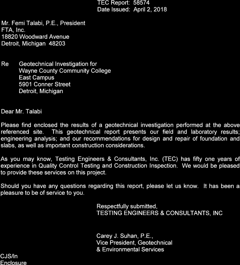


153

154

155

156
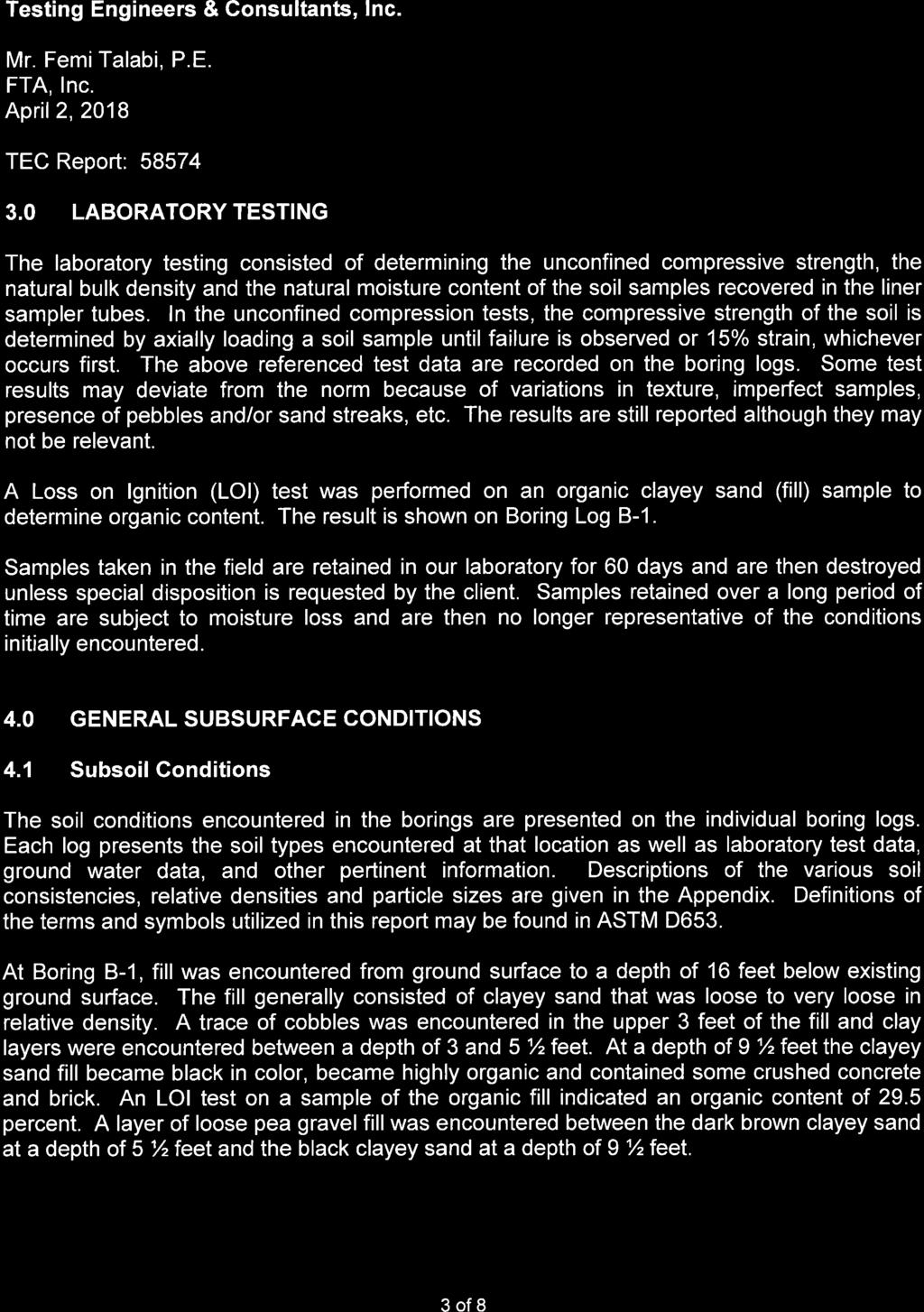
157

158

159

160

161


162

163

164
165
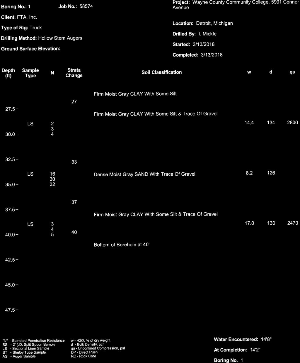
166

167
168
169

170

171

172