School of Engineering and Applied Science Building Miami University, Oxford, OH Technical Assignment 3 December 3, 2007
|
|
|
- Rosemary French
- 5 years ago
- Views:
Transcription


1 School of Engineering and Applied Science Building Miami University, Oxford, OH Technical Assignment 3 December 3, 2007 Jonathan Kirk AE 481W Senior Thesis The Pennsylvania State University Faculty Advisor: Dr. Andres Lepage
2 Table of Contents Executive Summary... 3 Lateral Resisting System... 4 Design Codes... 5 Load Combinations... 5 Loads... 6 Dead... 6 Live... 6 Wind... 7 Seismic... 8 Serviceability Considerations... 9 Analysis and Conclusions Appendices Appendix A Plans and Diagrams Appendix B Wind Analysis Appendix C Seismic Analysis Appendix D Overturning Appendix E Spot Checks


 direction and concentrically braced steel frames in the transverse (north-south) direction.")


3 Executive Summary Miami (OH) University ss School of Engineering and Applied Science Building consistss of four stories above grade, three of which are designated for classrooms and labs for students, as well as faculty offices. The fourth floor is a mechanical penthouse floor under a mansard roof which housess the building s main HVAC equipment. The building also has three levels of below-grade parking. The new building will connect to the existing Bentonn Hall by way of a skywalk at the 2 nd throughh 4 th floor. The architectural voice of the new building is largely based upon the aesthetic concepts of Benton Hall. The structure s gravity load system uses a steel frame with composite concrete floor slabs on steel columns. Lateral loads are resisted with steel moment frames in the longitudinal (east-west) direction and concentrically braced steel frames in the transverse (north-south) direction. The concrete floor slabs act as rigid diaphragms which transfer to load to each frame based on relative stiffness. This report will investigate the building s lateral framing system and check for its adequacy against both strength and serviceability requirements. After calculating the lateral loads acting on the building using ASCE 7-05, seismic loads weree found to control the structure s design in both directions of the building. A computer model was constructed using ETABS to help determine the distribution of thesee loads to each framing element. Building drift was calculated by the computer model and found to be well with the acceptable limitations. Spot checks of a few framing elements were checked against strength requirements and found to be sufficient. Finally, the building was checked against overturning the overturning moment caused by lateral forces, and the building s resisting moment caused by its self weight was found to be significantly higher than the overturning moment, so overturning will not be an issue. 3
4 Lateral Resistance System North-South Direction The lateral system in the transverse (short) direction of the building consists of four (4) single bay concentrically braced steel frames from the ground floor to the mechanical floor, of roughly the same size. There is only one cross brace at each of the three levels of the brace, sloping up from south-to-north, and are made of steel tubing, ranging in size from HSS8x8x¼ to HSS10x10x½. Elevations of each braced frame and their locations on plan can be found in Appendix A of this report. Additionally, there are two (2) single-span moment frames that support the skywalk that connects the west end of the School of Engineering and Applied Science Building to Benton Hall. At the eastern end of the building, there is also a moment frame with wide flange columns and HSS20x12x5/8 steel tube beams beside the stairwell. For lateral resistance from the mechanical floor to the roof, the mansard roof around the perimeter braces the roof, but is helped by four (4) single-span moment frames, which frame into the columns weak bending axes. East-West Direction The longitudinal (long) direction of the building utilizes an ordinary moment frame system, comprised of a total of eight (8) frames. There are four (4) full height moment frames that run from the ground floor all the way to the roof in the southern half of the building. The remaining four (4) frames in the northern half of the building are only two (2) stories tall, and stop at the low roof where the building steps back at the second floor level. Refer to the framing plans in Appendix A for the locations of each frame. The moment frames use a partially restrained moment connection that has plates bolted to the flanges, which then are welded with full-penetration welds into the columns supporting the beams. Garage There are three levels of below grade parking, mostly of which is directly beneath the main building. However, the northern end of the garage is below the exterior terrace in the rear of the building, where the grading drops down to approximately one level below the ground floor. This causes the weight of the ground floor to induce seismic forces, which are then transferred to the foundation through the exterior walls of the garage, which all act as shear walls. The walls range in thickness from 8 to 14 depending on their location. This report is focused primarily on the lateral resisting system above ground level, so the shear walls will have to be analyzed more carefully in upcoming reports. 4
5 Design Codes The School of Engineering and Applied Science Building was designed using the 2002 Ohio Building Code (OBC) with reference to ASCE 7-98 for building load determination procedures. ACI was used to design the concrete portions of the structure, and concrete masonry construction was designed using ACI 530.1, Specifications for Masonry Structures, and construction specification section The 1992 edition of AISC s Code of Standard Practice for Steel Buildings and Bridges, as modified by the construction documents, was used for design of steel members, and ANSI/AWS Structural Welding Code Steel D1.1 was used for design of welds. This report will use the more recent IBC 2006 with reference to ASCE 7-05 for building loads. ACI , Building Code Requirements for Structural Concrete, and the Load Resistance Factored Design procedure from the 13 th edition of AISC s Manual of Steel Construction will be used for design of the concrete and steel structural members, respectively. Load Combinations The following load combinations from Chapter 2 of ASCE 7-05 were used in evaluating ultimate factored loads used to check member capacities and for building overturning: (D + F) (D + F + T) + 1.6(L + H) + 0.5(Lr or S or R) D + 1.6(Lr or S or R) + (L or (0.8W) D + 1.6W + L +0.5(Lr or S or R) D + 1.0E + L + 0.2S D + 1.6W + 1.6H D + 1.0E + 1.6H 5
6 Design Loads Dead Loads Item Concrete (Normal Weight) Typical Floor Upper and Middle Garage 9" Slab Ground Floor 10" slab Ground Floor 12" slab Metal Deck Steel Framing Weight 150 pcf 62.5 psf psf 125 psf 150 psf 2 psf 8 psf Ceiling and Mechanical Allowance Typical Floor 15 psf Mechanical Floor 25 psf Roof 10 psf Garage 10 psf Partition Allowance 10 psf Roof Materials 4" Rigid Insulation 6 psf Roof Membrane 1 psf 1/2" Gypsum Board 2 psf Live Loads It is worthy to note that ASCE 7-05 does not specify live loads for labs such as the ones within the School of Engineering and Applied Sciences Building, which is what the majority of the space within the building is designated for. The designer chose to use a uniform load of 100 psf for upper level labs and 125 psf for labs at ground floor, which is what this report will use in the analysis. Area Typical Floor Labs at Ground Level Mechanical Equipment Rooms Plaza Roof Parking Decks PSE Basement at Upper Garage Level Utility Tunnel Design Live Load 100 psf 125 psf 150 psf 100 psf 25 psf 50 psf 125 psf 250 psf psf overburden 6
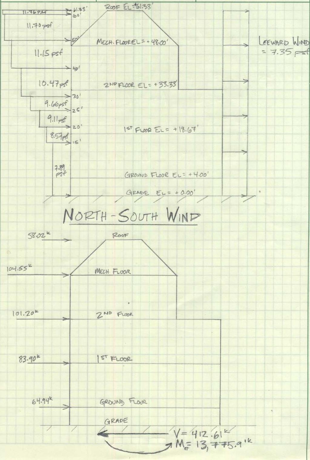
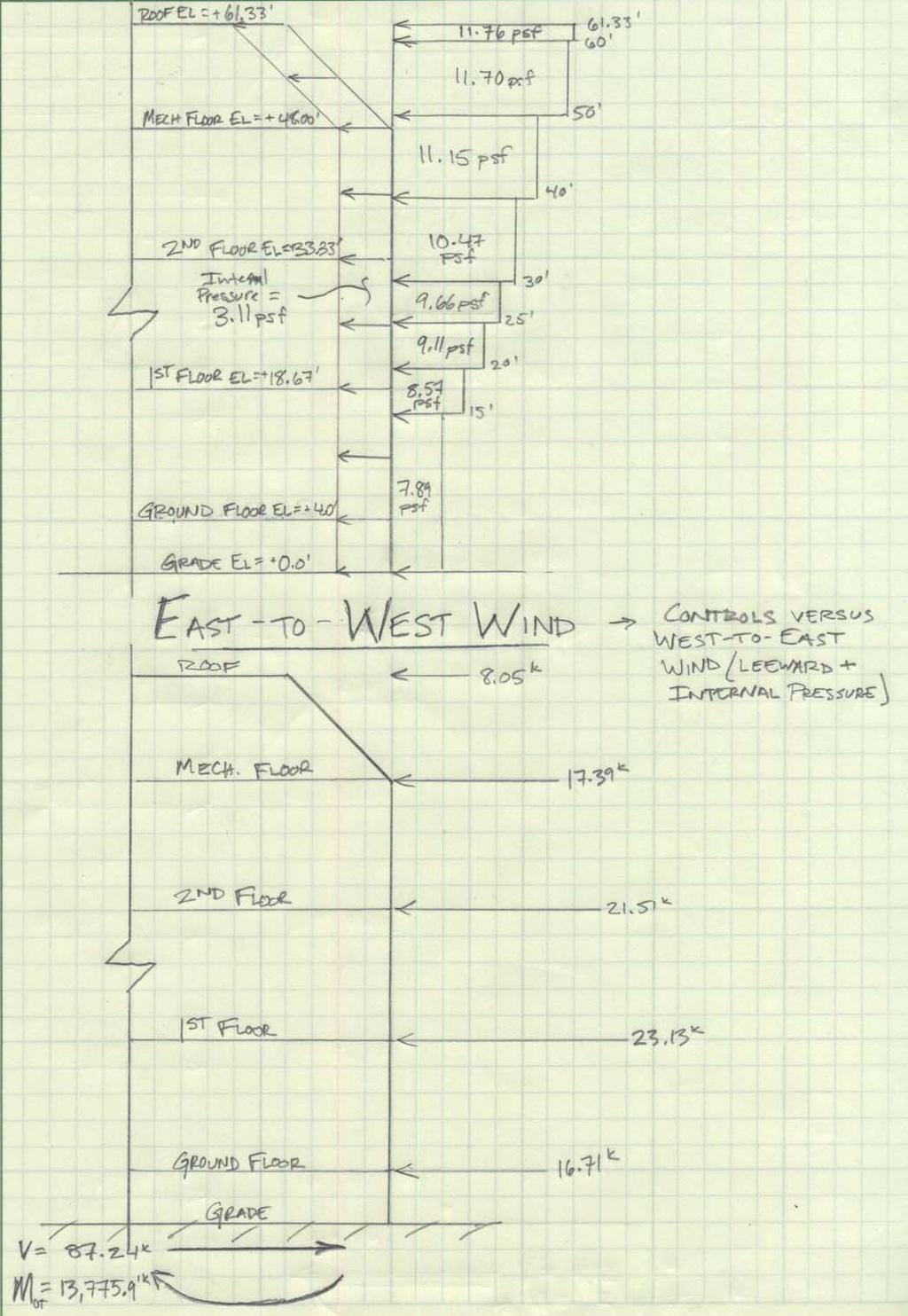
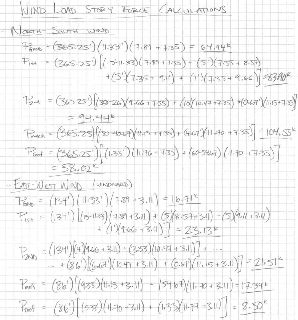
7 Wind Loads Wind loads determined for the School of Engineering and Applied Science Building were carried out under Section 6 of ASCE Factors were based on building characteristics, location, and height of the building. Assumptions include the normalization of the building s shape into a rectangle, ignoring any indentations or extrusions in the façade, and that the walls around the mechanical floor are actually plumb rather than sloped as a mansard roof was made to simplify the analysis, which results in a conservative wind force at that level. The building was found to be rigid and was analyzed as such. It is worthy to note that a large expansion joint exists where the new building attaches to the existing Benton Hall which is fairly open. As such, wind loading in the East-West direction has two effective modes, one where the windward pressure is acting in combination with the internal pressure, and one where the leeward pressure acts with the internal pressure, but not a combination of the windward and leeward pressure on the whole building. The building is in occupancy category III since it is a college facility with a capacity of over 500 people, which results in a wind importance factor of A summary of the analytical procedure is presented with this section. Refer to Appendix B for loading diagrams and a more detailed analysis. Design Summary Design Parameter Symbol Value ASCE 7 05 Reference Occupancy category III Table 1.1 Wind design Wind method Method 2 Wind importance factor I 1.15 Table 6 1 Exposure category B Section Enclosure classification Enclosed Wind directionality factor k d 0.85 Section & Table 6 4 Topographical factor k z 1.00 Table Basic wind speed V 90 mph Figure 6 1 Approximate building period T a s Equation Gust effect factor G 0.85 Section North South length ft East West length lower 2 levels ft East West length top 2 levels 86.0 ft Height above grade h n ft Base shear N S Wind V 413 k Overturning moment N S Wind M 13,776 ft k Base shear E W Wind V 87 k Overturning moment E W Wind M 2572 ft k 7
8 Seismic Loads Seismic loads determined for the School of Engineering and Applied Science Building were carried out under Section 11 of ASCE 7-05 using the equivalent lateral force design method. The ETABS computer model was helpful in determining the building s actual period in both the longitudinal and transverse directions, which allows for a more accurate calculation of the controlling C s. The building is in occupancy category III since it is a college facility with a capacity of over 500 people, which results in a seismic importance factor of Design assumptions and a summary of the analytical procedure are presented within this section. Refer to Appendix C for loading diagrams and a more detailed analysis. Seismic Design Summary Design Parameter Symbol Value ASCE 7 05 Reference Occupancy category III Table 1.1 Site classification C Table Seismic Design Category SDC B Tables & 2 Seismic importance factor I 1.25 Table Short period spectral response S s 0.171g Section Acceleration based Site coefficient F a 1.2 Table Maximum short period spectral response S DS Equation Spectral Response at 1 sec S g Section Velocity based site coefficient F v 1.7 Table Maximum spectral response at 1 sec S D g Equation Response modification factor R 3.0 Table Deflection amplification factor C d 3.0 Table N S building period T s Calculated on ETABS E W building period T s Calculated on ETABS Long period transition period T L 12 s Figure N S Seismic design coefficient C S Section E W Seismic design coefficient C S Section Height above grade h n ft Base shear N S loading V k Overturning moment N S loading M 32,475 ft k Base shear E W loading V k Overturning moment E W loading M 18,189 ft k 8
9 Serviceability Considerations Drift limits for both seismic and wind loadings were compared with drift values computed by the ETABS computer model under service loads. Seismic drift at each story was evaluated against Δ s = 0.015h sx in accordance with IBC Table Wind drift for the entire building was evaluated against the commonly accepted engineering value of Δ w = H/400. The following table shows the calculated drift values of a point at the northeast corner of the building under both seismic and wind loads. Story Height (ft) Seismic Story Drift ETABS Drift in x direction (in) ETABS Drift in y direction (in) Allowable Drift = 0.015h sx (in) Roof Mech nd st Ground Story Height (ft) Wind Story Drift ETABS Drift in x direction (in) ETABS Drift in y direction (in) Allowable Drift = H/400 (in) Roof Mech nd st Ground
10 Analysis and Conclusions As expected from previous investigations, seismic forces control the design of the lateral system in both the north-south and east-west directions. The increased stiffness of the braced frames in the transverse direction of the building cause the fundamental period to be approximately half of that in the longitudinal direction where moment frames make the structure relatively flexible. This resulted in a seismic base shear of nearly twice the magnitude for the braced frames to resist than the moment frames. It is also worthy to note that since the ground floor is slightly above grade, that it induces seismic forces in the system of a much larger magnitude than any other floor since the two-way slab floor comprises 45% of the total building weight considered for seismic base shear. For future investigation, if there is a way to raise the grading around the building to be at the ground floor diaphragm s level around the building s perimeter everywhere except the garage level, seismic forces will be drastically reduced, thus resulting in a much simpler lateral resisting system. The ETABS computer model formed was a very helpful tool in determining distribution of lateral forces to individual resisting elements. By calculating relative stiffness of each frame, the program can accurately determine how much load is transferred to each brace and moment frame. The building s relatively symmetrical shape causes very little eccentric rigidities, so the 5% accidental building eccentricity caused small torsional shears to be induced in framing elements near the building s perimeter. Using results from the computer model, strength checks were performed on a select number of lateral framing elements, all of which were found to be well within code limitations. ETABS was able to perform accurate drift calculations which were used to compare to industry standard limitations of H/400 for wind and 0.015h sx for seismic drifts. Displacement for both load cases in each direction was found to be well within the accepted limits. Finally, the structure was checked for possible overturning caused by lateral forces. The resisting moment caused by the building s self weight was found to be much higher than the largest overturning moment induced by lateral forces, so no net tension will need to be considered for foundation design. 10
 (Looking West)")
11 Appendix A Plans and Diagrams Braced Frame Diagrams Elevation at Lines 3 & 8 Elevation at Lines 5 & 6 (Looking West) (Looking West) 11
12 First Floor Framing Plan Area A (West half of building) Legend Braced Frame (red dotted line) Moment Frame (blue dashed line) 12
13 First Floor Framing Plan Area B (East half of building) Legend Braced Frame (red dotted line) Moment Frame (blue dashed line) 13
14 Roof Framing Plan Area A (West half of building) Legend Moment Frame (blue dashed line) 14
15 Roof Framing Plan Area B (East half of building) Legend Moment Frame (blue dashed line) 15

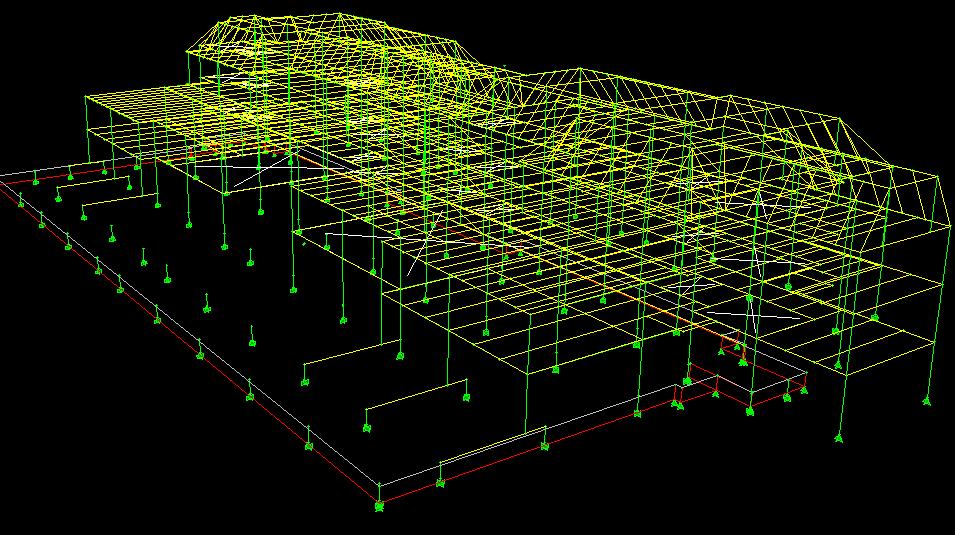
16 ETABS Model 16
17 Appendix B Wind Analysis Height above ground (ft) Kz qz (psf) North South Wind Loading Pressure (psf) Windward Leeward Sidewall Internal ± ± ± ± ± ± ± ±3.11 Height above ground (ft) Kz qz (psf) East West Wind Loading Pressure (psf) Windward Leeward Sidewall Internal ± ± ± ± ± ± ± ±3.11 Wind Direction North South Wind East to West Wind West to East Wind Overturning Overturning Overturning Floor Height above ground (ft) Force (k) Moment (ft k) Force (k) Moment (ft k) Force (k) Moment (ft k) Roof Mech nd st Ground Sum
18 18
19 19
20 20
21 Appendix C Seismic Analysis Project Location Oxford, OH Project Latitude Project Longitude Occupancy Category III Seismic Importance Factor 1.25 Site Classification C S s 0.171g F a 1.2 S MS = F a S s = 0.205g S DS = (2/3)S MS = 0.137g S g F v 1.7 S M1 = F v S s = 0.124g S D1 = (2/3)S M1 = 0.083g Seismic Design Category B Structural Steel System Seismic Resisting System Not Specifically Detailed for Seismic Resistance Direction N S E W R C d h n C u C t x T a = C t h n x = s s T max = C u T a = s s T actual * s s T L 12 s 12 s * Note: T actual calculated by ETABS 21

 Exponent k k Σ w i h i C vx Story Force f x (k) Shear V x (k) Moment M x (ft k) 61.33 48.00 33.00 18.67 4.")

22 North-South Braced Frames C s = min S DS /(R/I) = S D1 /(T(R/I)) = S D1 TL/(T 2 L (R/I)) = Controlling C s = W = 14,669 k V = C s W = k Level Roof Mech. 2nd 1st Grnd. Sum Lateral Seismic Force Distribution Through the Levels (North South Braced Frames) Story Height h x (ft) Story Weight W (k) Exponent k k Σ w i h i C vx Story Force f x (k) Shear V x (k) Moment M x (ft k) W = V = k M = ft k 22

 Exponent k k Σ w i h i C vx Story Force f x (k) Shear V x (k) Moment M x (ft k) 61.33 48.00 33.00 18.67 4.")

23 East-West Moment Frames C s = min S DS /(R/I) = S D1 /(T(R/I)) = S D1 TL/(T 2 L (R/I)) = Controlling C s = W = 14,669 k V = C s W = k Level Roof Mech. 2nd 1st Grnd. Sum Lateral Seismic Force Distribution Through the Levels (East West Moment Frames) Story Height h x (ft) Story Weight W (k) Exponent k k Σ w i h i C vx Story Force f x (k) Shear V x (k) Moment M x (ft k) k 2579 k 2457 k 2314 k 6612 k W = V = k M = ft k 23


24 Appendix D Overturning 24

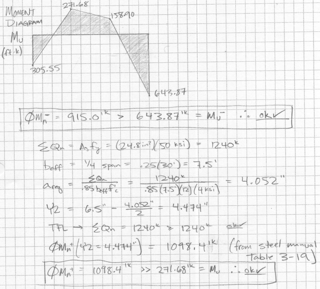
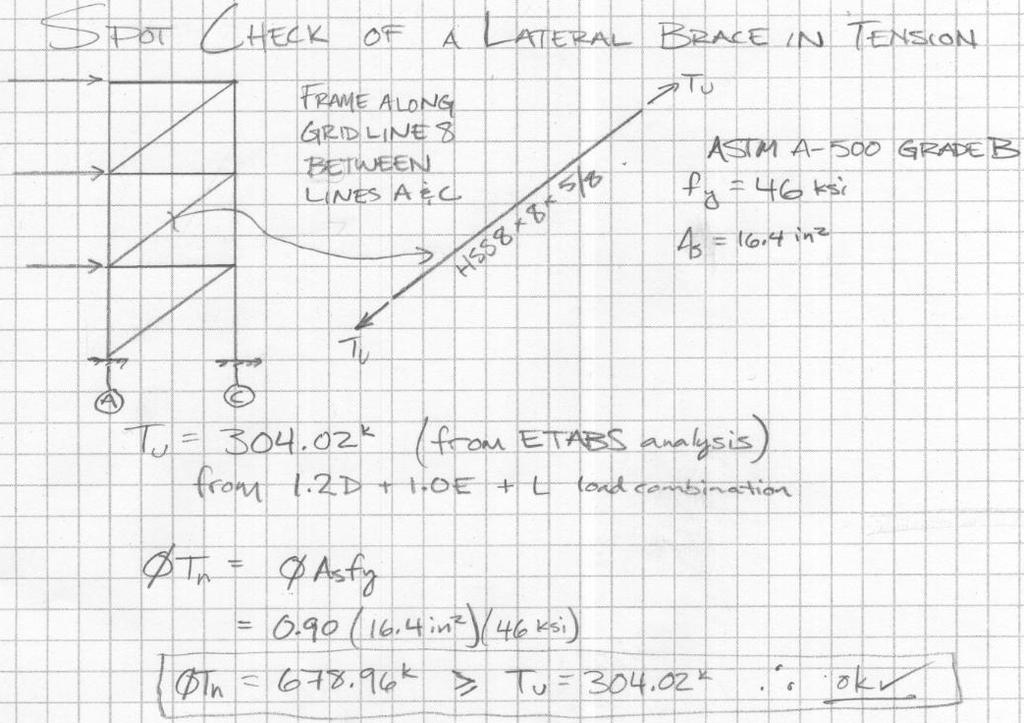
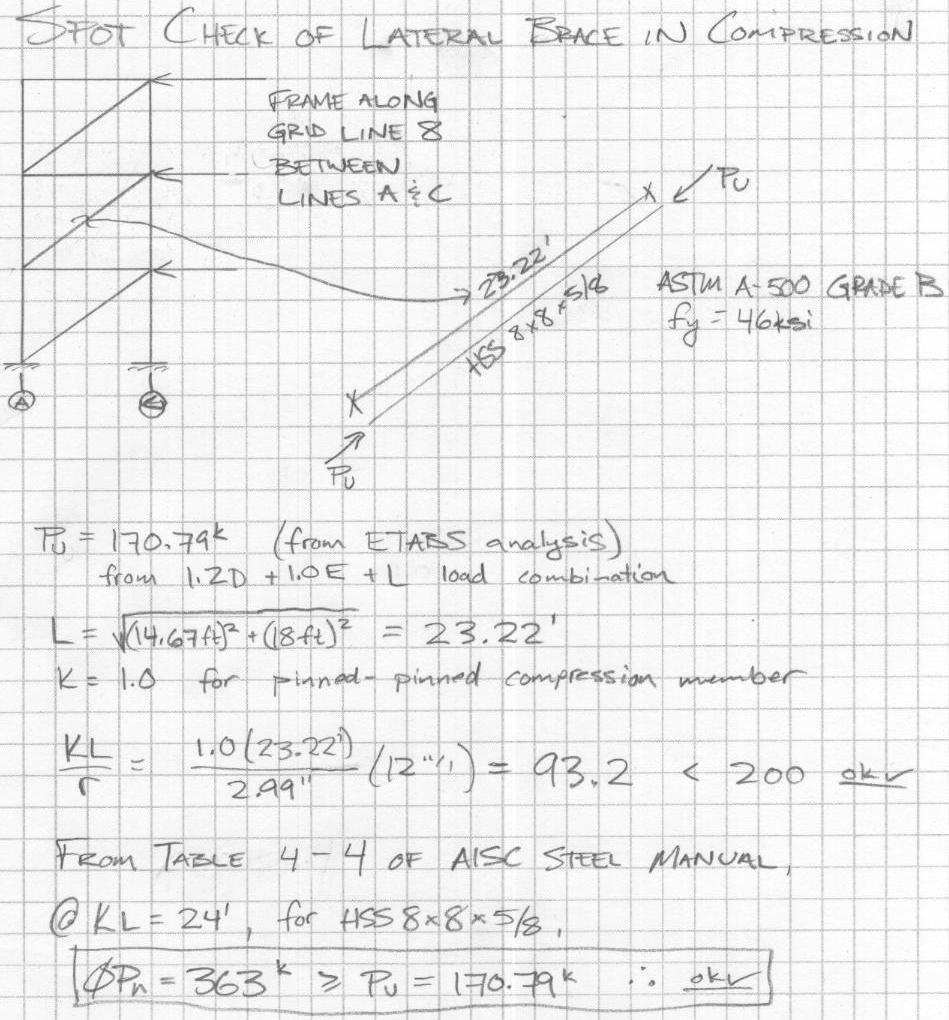
25 Appendix E Spot Checks 25
26 26
27 27
28 28