Fire Resistive Design of Exposed Timber Structures
|
|
|
- Jared Andrews
- 5 years ago
- Views:
Transcription
.")
1 Fire Resistive Design of Exposed Timber Structures Heavy Timber & One Hour Fire Rating Paul C. Gilham, P.E., S.E. Western Wood Structures, Inc. The Wood Products Council is a Registered Provider with The$ American$Ins.tute$of$Architects$Con.nuing$Educa.on$Systems$(AIA/CES). Credit(s) earned on completion of this program will be reported to AIA/CES for AIA members. Certificates of Completion for both AIA members and non-aia members are available upon request. This program is registered with AIA/CES for continuing professional education. As such, it does not include content that may be deemed or construed to be an approval or endorsement by the AIA of any material of construction or any method or manner of handling, using, distributing, or dealing in any material or product. " " Questions related to specific materials, methods, and services will be addressed at the conclusion of this presentation.! Fire Resistive Design of Exposed Timber Structures Copyright Materials! " This presentation is protected by US and International Copyright laws. Reproduction, distribution, display and use of the presentation without written permission of the speaker is prohibited." " Learning Objectives. Learn where exposed timber fire resistive construction is allowed in the IBC.. Learn the characteristics of Heavy Timber 3. Learn the methods of obtaining hour fire resistive rating for exposed timber members using IBC section Learn the methods of obtaining hour fire resistive rating for exposed timber members using NDS chapter 6 The Wood Products Council "


2 Fire Resistive Design of Exposed Timber Structures Fire Resistive Design of Exposed Timber Structures Fire Resistive Design of Exposed Timber Structures Fire Resistive types of exposed wood members Heavy Timber Background of Heavy Timber Minimum Sizes Connections Approved Uses One Hour Fire Rated Wood Members IBC section Details NDS Chapter 6 Examples Fire Resistive Design of Exposed Timber Structures IBC Types (IBC 6) Type I & Type II Non-combustible materials except as permitted in section 63 Type III Exterior walls are non-combustible materials, interior building elements are of any material permitted by the code. (Allows FRT framing in exterior walls) Type IV Exterior walls are non-combustible and interior building elements are solid or laminated wood without concealed spaces. (Allows FRT framing in exterior walls and -hour assemblies in interior partitions.) Type V Structural elements, exterior walls and interior walls are of any materials permitted by the code.
3 Heavy Timber Background of heavy timber construction. Heavy-timber construction, as applied to buildings, means that in which walls are of approved masonry or reinforced concrete; And in which the interior structural elements, including columns, floors and roof construction, consists of heavy timbers with smooth flat surfaces, assembled to avoid thin sections, sharp projections and concealed spaces; And which all structural members which support masonry walls shall have a fire-resistance rating of not less than three hours; And other structural members of steel or reinforced concrete, if used in lieu of timber construction, shall have a fire resistance rating of not less than one hour. 943 national building code. Heavy Timber Minimum size of members (IBC table 6.4) Member Nominal Solid Sawn GLULAM Columns Beams Supporting Floor 8x8 7½ x 7½ 6¾ x 8¼ Supporting Roof 6x8 5½ x 7½ 5 x 8¼ Floor 6x 5½ x 9½ 5 x ½ Roof 4x6 3½ x 5½ 3 x 7½ Arches springing from floor Supporting floor 8x8/8x8 7½ x 7½ 6¾ x 9 Not supporting floor 6x8/6x6 5½ x 7½ /5½ 5 x 8¼ /6 Arches springing from top of wall Trusses 4 x 6 3½ x 5½ 3 x 6 7 / 8 Floor 8x8 7½ x 7½ 6¾ x 9 Roof 4x6 3½ x 5½ 3 x 6 7 / 8 Heavy Timber Floors. Without concealed spaces. Sawn or glued-laminated planks, T&G or splined of not less than 3 in. nominal, covered with T&G laid crosswise or diagonally or 5/3 wood structural panels. Planks not less than 4 in. nominal on edge close together, well spiked (nail laminated) with flooring or 5/3 wood structural panels. The lumber shall be laid so that no continuous line of joints will occur except at points of support. Floors shall not extend closer than ½ inch to walls. Such ½ inch space shall be covered by a molding fastened to the wall and arranged so that it will not obstruct the swelling and shrinking movements of the floor. Corbeling of masonry walls under floors may be used in place of of such molding. Heavy Timber Roofs. No concealed spaces. Sawn or glued-laminated plank, T&G or splined not less than in. nominal or /8 wood structural panels or 3 in. nominal on edge close together, well spiked (nail laminated). Laid as required for floors


4 Heavy Timber Partitions Of solid wood construction formed by not less than two layers of -inch matched boards or Laminated construction 4 thick -hour fire resistance construction Where code provisions require fire separation such as at a corridor, -hour fire resistive construction must be used. Heavy Timber Details. Approved wall plate boxes or hangers at walls. Girders & beams shall fit closely around columns and adjoining ends shall be cross tied to each other or intertied by caps or ties. Where intermediate beams are used to support a floor, they shall rest on top of girders or shall be supported by ledgers or blocks securely fastened to the sides of the girders, or they may be supported by approved metal hangers into which the beams shall be closely fitted. Every roof girder and at least every other roof beam shall be anchored to its supporting member. Roof decks supported by a wall shall be anchored every max. Scappoose High School Gym Mighty Ducks Ice Arena, Anaheim, CA
 UL 6 65 55 65 55 65 5 4 Stories (S)/Area(A) A- S UL 5 3 3 3 A UL UL 5,5 8,5 4, 8,5 5,,5 5,5 A- S UL 3 3 3 A")

5 Lemay America s Car Museum Tacoma, WA Port of Portland Terminal 5 Table 53 Table 53 Allowable Building Heights and Areas Allowable Building Heights and Areas Type of Type of Type I Type II Type III Type IV Type V Type I Type II Type III Type IV Type V Group A B A B A B HT A B Height (ft) UL Stories (S)/Area(A) A- S UL A UL UL 5,5 8,5 4, 8,5 5,,5 5,5 A- S UL A UL UL 5,5 9,5 4, 9,5 5,,5 6, A-3 S UL A UL UL 5,5 9,5 4, 9,5 5,,5 6, A-4 S UL A UL UL 5,5 9,5 4, 9,5 5,,5 6, A-5 S UL UL UL UL UL UL UL UL UL A UL UL UL UL UL UL UL UL UL B S UL A UL UL 37,5 3, 8,5 9, 36, 8, 9, E S UL A UL UL 6,5 4,5 3,5 4,5 5,5 8,5 9,5 F- S UL A UL UL 5, 5,5 9,, 33,5 4, 8,5 F- S UL A UL UL 37,5 3, 8,5 8, 5,5, 3, H- S NP A, 6,5, 7, 9,5 7,,5 7,5 NP H- S UL 3 A, 6,5, 7, 9,5 7,,5 7,5 3, H-3 S UL A UL 6, 6,5 4, 7,5 3, 5,5, 5, H-4 S UL A UL UL 37,5 7,5 8,5 7,5 36, 8, 6,5 H-5 S UL A UL UL 37,5, 8,5 9, 36, 8, 9, Group A B A B A B HT A B Height (ft) UL Stories (S)/Area(A) I- S UL A UL 55, 9,, 6,5, 8,,5 5,5 I- S UL 4 NP A UL UL 5,,, NP,,5 6, I-3 S UL 4 A UL UL 5,,,5 7,5,,5 6, I-4 S UL A UL 6,5 6,5 3, 3,5 3, 5,5,5 6, M S UL UL UL A UL UL,5,5 8,5,5,5 UL UL R- S UL A UL UL 4, 6, 4, 6,,5 8, 9, R- S UL A UL UL 4, 6, 4, 6,,5 8,5 9,5 R-3 S UL A UL UL UL UL UL UL UL 4, 8,5 R-4 S UL A UL UL 6, 6, 4, 6,,5, 3, S- S NP A, 48, 6, 7,5 6, 7,5 5,5 7,5 NP S- S UL A, 79, 39, 6, 39, 6, 38,5 7,5 3, U S UL A UL 35,5 9, 8,5 4, 8,5 8,, 5,
6 TABLE 6 FIRE-RESISTANCE RATING REQUIREMENTS FOR BUILDING ELEMENTS (hours) Building Element Type I Type II Type III Type IV Type V A B A d B A d B HT A d B TABLE 6 FIRE-RESISTANCE RATING REQUIREMENTS FOR BUILDING ELEMENTS (hours) Building Element Type I Type II Type III Type IV Type V A B A d B A d B HT A d B Primary Structural Frame (See Section ) 3 a a HT Primary Structural Frame (See Section ) 3 a a HT Bearing Walls Exterior f,g 3 Interior 3 a a /HT Bearing Walls Exterior f,g 3 Interior 3 a a /HT Nonbearing walls and partitions Exterior See Table 6 Nonbearing walls and partitions Exterior See Table 6 Nonbearing walls and partitions Interior See Section Floor construction and secondary members (see Section ) HT Nonbearing walls and partitions Interior See Section Floor construction and secondary members (see Section ) HT Roof construction and secondary members (see Section ) ½ b b,c b,c c b,c HT b,c Roof construction and secondary members (see Section ) ½ b b,c b,c c b,c HT b,c a. Roof supports: Fire-resistive ratings of primary structural frame and bearing walls are permitted to be reduced by hour where supporting a roof only. b. Except in Group F-, H, M and S- occupancies, fire protection of structural members shall not be required, including protection of roof framing and decking where every part of the roof construction is feet or more above any floor immediately below. Fire-retardant-treated wood members shall be allowed to be used for such unprotected members. c. In all occupancies, heavy timber shall be allowed where a -hour or less fire-resistance rating is requried. a. Roof supports: Fire-resistive ratings of primary structural frame and bearing walls are permitted to be reduced by hour where supporting a roof only. b. Except in Group F-, H, M and S- occupancies, fire protection of structural members shall not be required, including protection of roof framing and decking where every part of the roof construction is feet or more above any floor immediately below. Fire-retardant-treated wood members shall be allowed to be used for such unprotected members. c. In all occupancies, heavy timber shall be allowed where a -hour or less fire-resistance rating is required. IBC NDS Chapter 6

7 IBC Section Based on work by T.T. Lee at the National Research Council of Canada in the 97s. Assumptions..4 in../hr char rate. Reduction of strength and stiffness for.5 in. in the heated zone ahead of the char front..8 factor used to account for reduction of strength and stiffness. Accounts for design to ultimate strength ratio. Ignores increased rate of charring at corners. Equation relates size to time t = (B-b)/β = (D-d)/β" Equation relates Ultimate strength to Design strength BD kz 6 bd = α 6 The code specified live load is to be used in calculating Z Fire resistive rating of Timber members IBC Section Beams t f t f b =.54Zb(4 ) 4-sided exposure d b =.54Zb(4 ) 3-sided exposure d Z =.3 For R <.5.3 Z =.7 + R For R >.5
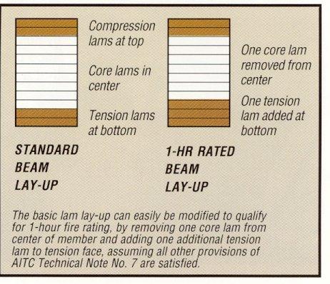
8 Fire resistive rating of Timber members per UBC Std. 7-7 Columns d t f =.54Zd(3 ) 4-sided exposure b d t f =.54Zd(3 ) 3-sided exposure b Z Z For K e l/d < =.5.3 =.9 + R For R <.5 For R >.5 For K e l/d > Z =.3 For R <.5 Z R = For R >.5 Additional details.. Minimum nominal width = 6.. Connections and fastenings supporting members shall be protected for equivalent fire resistance. 3. Replace one core lamination with an extra tension lamination. 4. Glued-laminated timber members shall be marked Fire-rated One-hour.
9

10 Fire resistive rating of Timber members per NDS Chapter 6 Calculates the capacity of fire-resistive members using same mechanics as Lee. Assumes failure occurs when applied load exceeds member capacity based on reduced size and average ultimate stress. i.e. D + L < K R ASD Section properties are computed assuming an effective char rate, β eff, at a given time, t. Effective char rate accounts for rounding of the member at the corners and reduction of strength and stiffness of the heated zone. The code prescribed Live Load is to be used in the calculations. Advantages of NDS Chapter 6 method.. All terms can be easily determined giving the designer a more complete sense of the performance of the member.. The method for designing fire rated compression members is consistent with the non-fire resistive design of compression members. 3. This method includes procedures for designing tension members. 4. This method provides procedures for designing members subjects to combined axial forces and bending moments such as arches or continuous truss chords. 5. This method provides procedures for designing timber decks. 6. Two-hour fire resistive members can be designed using these principles. Fire resistive rating of Timber members per NDS Chapter 6 Reduced Cross Sectional Properties Section Property Four sided exposure Three sided exposure Area A(t)= (B-β eff t)(d-β eff t) A(t)= (B-β eff t)(d-β eff t) Section Modulus S(t)= (B-β eff t)(d-β eff t) /6 S(t)= (B-β eff t)(d-β eff t) /6 Moment of Inertia I(t)= (B-β eff t)(d-β eff t) 3 / I(t)= (B-β eff t)(d-β eff t) 3 / Where: β eff.β = t n.87 and: βn =.5 in/hr $3/4!x!6$/!!
11 Fire resistive rating of Timber members per NDS Chapter 6 Allowable Design Stress to Average Ultimate Strength Adjustment Factors /k c Assumed COV K Bending, F b COV b.6.85 Tensile, F t COV t.6.85 Compression F c COV c.6.58 Buckling, E COV E..3 Fire resistive rating of Timber members per NDS Chapter 6 Design a one hour beam to span -, spacing = 6 - o.c., q dead =5psf, q live = psf w total = 6(5+) = 75 plf M = wl /8 = 37,5 ft. lbs. Try a 5 / 8 x 5 GLULAM DF 4F-V4 C V =.987 S = bd /6 = 9.9 in 3 F b = F b * (C L or C V ) = 4 *.987 = psi M = F b * S = * 9.9/ = 37,77.53 ft-lbs. OK Fire Check. Choose required fire endurance. Calculate depth of char 3. Calculate reduced section property 4. Calculate Average Ultimate Stress 5. Calculate Allowable Capacity. Choose one hour fire endurance. β.(.5) =.87. eff =.8in / hr. 3. a = β eff * t =.8 in/hr * hr =.8 in. 4. S f = (b-a)(d-a) /6 = ( )(5-.8) /6 = 44.9 in 3 5. F bf = F b (C V or C L )(.85) = 6,7.69 psi 6. M f = F bf * S f = 6,7.69 * 44.9/ = 4,88.56 ft. lbs. < 37,5 ft. lbs. NG
(d-a) /6 = (5.5-3.6)(9.5-.8) /6 = 79.")


12 Birchwood Community Church Anchorage, Alaska Try 5 /8 x 9 ½ glulam 4F-V4. S f = (b-a)(d-a) /6 = ( )(9.5-.8) /6 = in 3. F bf = F b (C V )(.85) 4(.9573)(.85) = 6, psi 3. M f = F bf * S f = 6, * 79.63/ = 43, ft. lbs. > 37,5 ft. lbs. OK Fire Resistive Design of Exposed Timber Structures Available Resources Fire Resistive Design of Exposed Timber Structures Available Resources Technical Note Calculating the Fire Resistance of Exposed Wood Members Wood Data 5 Heavy Timber
13 Fire Resistive Design of Exposed Timber Structures Summary Fire Resistive Design of Exposed Timber Structures Two methods of code approved fire protection are available using exposed timber members Heavy timber conforming to IBC 6.4 utilizes large timber members and is based on positive experience. Thank You One hour fire ratings can be obtained using IBC section or NDS Chapter 6 Questions? This concludes The American Institute of Architects Continuing Education Systems Course Paul%C.%Gilham,%P.E.,%S.E.% Chief%Engineer% Western!Wood!Structures,!Inc.! paulg@westernwoodstructures.com!