TECHNICAL MANUAL. PVL Connecting Loop. Wall Connecting Loop Box with Single Wire
|
|
|
- Kenneth Harper
- 5 years ago
- Views:
Transcription


1 TECHNICAL MANUAL PVL Connecting Loop Wall Connecting Loop Box with Single Wire Version: PEIKKO GROUP 11/2012


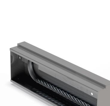
2 PVL Connecting Loop Single wire wall connecting loop Benefits of PVL Easy to install, individual boxes are installed to formwork. Flexible wire loop stays in opened position due to patented structure. Anchoring tail is easy to place into reinforcement. Stepped box shape secures the box in to the concrete. Wire Loop boxes are installed to the formwork according to spacing needed to bear the shear loads, before the panel is casted. After removing the formwork, protective tape is removed and the loop is opened with for example a hammer or a pin. Pair of boxes and the vertical rebar installed into loops form a joint which resists vertical shear forces, together with the concrete grout in the joint. Peikko PVL Connecting Loops are available in loop lengths 60, 80, 100, 120 and 140 mm.
3 Contents About PVL Connecting Loop 4 1. Product properties Structural behavior Limitations of application Loading and environmental conditions Interaction in the joint Positioning of PVL to the joint Other properties Resistances...6 Selecting PVL Connecting Loop 7 Annex A Additional reinforcement 8 Installation of PVL 11 Revision: 001*

4 About PVL Connecting Loop 1. Product properties PVL Connecting Loop consists of recess box which anchors itself to concrete well thanks to its stepped side form, and a wire, which together with the box forms are a load bearing structure. Spacing of PVL Connecting Loops in the joint depends on the shear loads to be transferred. Boxes are installed to the formwork of wall panels before concreting. Wire Loop boxes are installed to the formwork according to spacing needed to bear the shear loads, before the panel is casted. After removing the formwork, protective tape is removed and the loop is opened with for example a hammer or a pin. Pair of boxes and the vertical rebar installed into loops form a joint which resists vertical shear forces, together with the concrete grout in the joint. Picture 1. PVL Connecting Loops in the joint of wall panels 1.1 Structural behavior PVL Connecting Loop resists shear forces with a tension bar, which consists of loops and the vertical rebar in the joint, and a compression bar, which forms between the edges of the recess boxes from concrete. 1.2 Limitations of application PVL Connecting Loops are designed to be used in conditions which are explained later in this technical manual. If these conditions are not fulfilled, Peikko Technical Support can recommend other Peikko solutions Loading and environmental conditions Resistances of PVL Connecting Loop connections are defined according to loop spacing and compression strength of the concrete grout in the joint. Resistances are calculated according to Eurocode 2 parts 1-1 and 1-2. It is assumed that no forces, compression or tension, parallel to wall panels and loops effect to the joint. Only shear force effecting in the vertical joint is taken into account. Concrete grout shall have minimum the same compression strength than the concrete of the wall panels, minimum C25/30. PVL Connecting Loops must not be used In joints, which are exposed to such a seismic or dynamic strains which exceed the deformation capacity of concrete grout in the joint. For lifting or as a lifting loop. 4 PVL Connecting Loop
5 About PVL Connecting Loop If PVL connecting loops are used in fire resistant load bearing walls, the concrete cover thickness must be effective enough so that the wire loop will not reach its critical temperature T crit. = 350 C Interaction in the joint Minimum value for thickness of the wall panels and ideal joint width is given in Table 1. Table 1. Minimum value for thickness of the wall panels and ideal joint width. PVL d wall d joint overlap L d joint rebar [mm] PVL PVL PVL PVL PVL Positioning of PVL to the joint Picture 2. Minimum distances for PVL Connecting Loop. PVL 60 PVL 120 PVL 140 d wall overlap min 120 min 200 min 90 min 350 min 90 min 150 min 250 min 250 min 90 min 120 min 200 Picture 3. Height tolerance of the loops [mm]. max. 4 d wire < ~20 mm Version: Peikko Group 11/2012 5
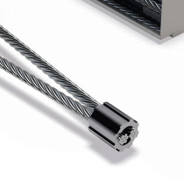
6 About PVL Connecting Loop 1.3 Other properties Peikko PVL Connecting Loops are manufactures from following materials in Peikko China factory: Box Q195, thickness 0,7 mm GB/T Steel sheet, zinc plated and passivated Ferrule 16 Mn GB/T Cover Tape Wire Loop 6x19+IWS 1770 N/mm 2 GB/T Patented structure solid core wire based on standard EN Dimensions of PVL Connecting Loops are shown in Table 2. Peikko Group s production units are externally controlled and periodically audited on the basis of production certifications and product approvals by various organizations, including Inspecta Certification, VTT Expert Services, Nordcert, SLV, TSUS and SPSC among others. Table 2. Main dimensions of PVL Connecting Loops L2 B H PVL L1 L2 B H SL wire Ø [mm] PVL PVL PVL PVL PVL SL L1 2. Resistances Resistances of PVL Connecting Loop connections are defined according to loop spacing and compression strength of the concrete grout in the joint. Resistances are calculated according to Eurocode 2 parts 1-1 and 1-2. Table 3. Design Shear resistance V Rd [kn/m] of PVL 60, PVL 80, PVL 100 and PVL 120 Wire Loop for the joint described in Picture 2, Annex A, Additional reinforcement. Concrete strength Spacing of loops [mm] (EC 2) C25/ C30/ C35/ C40/ C45/ C50/ Table 4. Design Shear resistance V Rd [kn/m] of PVL 140 Wire Loop for the joint described in Picture 2, Annex A, Additional reinforcement. Concrete strength Spacing of loops [mm] (EC 2) C25/ C30/ C35/ C40/ PVL Connecting Loop
7 Selecting PVL Connecting Loop Selecting PVL Wire Connecting Loop PVL Wire Loop is selected according to wall thickness and joint width. Generally PVL 80 is used for non-load bearing walls and PVL 120 for load bearing / stiffening walls. PVL 140 is used for higher loads in load bearing and stiffening structures. Spacing of PVL Wire Loops is selected according to shear force effecting to the joint in ultimate limit state. Shear resistance in direction perpendicular to the Wall panels surface depends on the shape of the cross-section of the joint and reinforcement of the panels around the joint. Concrete dowel defines the shear resistance perpendicular to the wall. Picture 4. Shear force perpendicular to the joint. V d V d Version: Peikko Group 11/2012 7
8 Annex A Additional reinforcement Additional reinforcement Picture 5. Anchoring the PVL Connecting Loops in the joint of precast elements. 3 Ø10 2 U-stirrups Ø6 1 Ø12, PVL 140: Ø16 4 Ø10 if wire is bent Additional reinforcement PVL 60, 80, 100, 120 Mesh on both surfaces mesh on both surfaces min. Ø6 k 150 U-stirrups Ø8 or 2 x Ø6 edge reinforcement min. 2 Ø10 Central mesh mesh min. Ø6 k 150 edge reinforcement min. 2 Ø10 No meshes edge reinforcement min. 2 Ø10 wire loop min. c/c 600 mm min. distance from element top and bottom edge 450 mm 8 PVL Connecting Loop
9 Annex A Additional reinforcement U-stirrups, alternatives: Stirrup Ø8 for every PVL wire, spacing the same as PVLs min 80 Stirrup Ø6, spacing 1/2 of PVLs spacing min min B = 0,5 x k k min 90 B = 0,5 x k A A 160 B = 0,5 x k k min 90 A A 160 min 80 min 80 Stirrups Ø8, c/c as PVLs Stirrups Ø6 c/c 0,5 x spacing of PVLs Mesh min. Ø6 k 150 or 189 mm 2 /m Mesh min. Ø6 k 150 or 189 mm 2 /m Version: Peikko Group 11/2012 9
10 Annex A Additional reinforcement Additional reinforcement options PVL 140 Reinforcement: B500B. Stirrup Ø8 to every PVL wire, spacing the same than PVLs 2 Stirrups Ø6, spacing 100 mm up and 100 mm down from PVL s loop >350 > >200 >200 Stirrups Ø8 spacing according to PVLs 2 Stirrups Ø6, spacing 100 mm up and 100 mm down from PVLs loop -Mesh on both surfaces min. Ø6 c/c 150 or 189 mm 2 /m -Edge rebars min. 2 Ø 10 -Mesh on both surfaces min. Ø6 c/c 150 or 189 mm 2 /m -Edge rebars min. 2 Ø PVL Connecting Loop


11 Installation of PVL Installation of PVL Connecting Loop In precast factory PVL Connecting Loops are fixed to the formwork with nails. Common way is to make a plywood strip, which forms the recess shape to wall panel end. Then PVLs are nailed with correct spacing to this reusable plywood strip. When concrete has hardened and formwork is removed, protective tapes can be removed and loops opened for example with hammer. Due to patented structure of the wire, loops will remain in opened horizontal position. On construction site Wall panels are installed according to plans and supported. Vertical rebar is installed into a joint, and horizontal position of the loops is checked. After formwork has been done, concrete grout is poured or pumped into the joint. 90 ± 10 NOTE: Wire maintains its full strength in normal use, where maximum 3 open-close bendings takes place.
12 Notes 12 PVL Connecting Loop
13 Notes Version: Peikko Group 11/
14 Notes 14 PVL Connecting Loop
15 Technical Manual Revisions Version: PEIKKO GROUP 11/2012. Revision:001* New cover design for 2018 added. Version: Peikko Group 11/
16 Resources DESIGN TOOLS Use our powerful software every day to make your work faster, easier and more reliable. Peikko design tools include design software, 3D components for modeling programs, installation instructions, technical manuals and product approvals of Peikko s products. peikko.com/design-tools TECHNICAL SUPPORT Our technical support teams around the world are available to assist you with all of your questions regarding design, installation etc. peikko.com/technical-support APPROVALS Approvals, certificates and documents related to CE-marking (DoP, DoC) can be found on our websites under each products product page. peikko.com/products EPDS AND MANAGEMENT SYSTEM CERTIFICATES Environmental Product Declarations and management system certificates can be found at the quality section of our websites. peikko.com/qehs