By Dr Martin Kelm Technical Director FOWPI Foundation Design OWF Gujarat. 20 March 2018 Foundation Design Workshop
|
|
|
- Giles Conley
- 5 years ago
- Views:
Transcription

1 By Dr Martin Kelm Technical Director FOWPI Foundation Design OWF Gujarat 1
2 Agenda 1. Introduction to COWI 2. Foundation types 3. Introduction to foundation design 4. Basis of design 5. Advisory foundation design 2

3 1. Introduction to COWI Founded in 1930 by Christen Ostenfeld Wriborg Jønson 3
4 Introduction to COWI COWI IN NUMBERS 798 MILLION EUR IN TURNOVER MORE THAN 85 YEARS OF HISTORY WORKING IN 124 COUNTRIES OVER 6,600 EMPLOYEES 4

5 Introduction to COWI Marine offices OSLO GLASGOW VANCOUVER HAMBURG BOSTON CONNECTICUT HONG KONG 5
6 Introduction to COWI Main offshore wind offices Oslo Glasgow Aalborg Aarhus Lyngby Hamburg London About 150 staff working with offshore wind foundation design
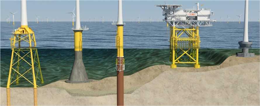
7 2. Foundation types Due to its site-specific character, offshore wind foundations represent a significant part of a project's capital expenditure, and therefore optimization of its structure might lead to substantial savings. 7
8 Foundation types 8
9 Foundation types Investigated Steel jackets Concrete gravity based foundations Monopiles 9

10 Foundation types Concrete gravity based foundations Pros Cons + cheap construction - heavy + local construction - difficult to install + versatile 10

11 Foundation types Steel jackets Pros Cons + widely used - relatively expensive + relatively light 11

12 Foundation types Monopiles Pros Cons + widely used - relatively heavy + supply chain - special equipment needed + fast to install + relatively cheap + versatile 12
13 Foundation types Selection criteria Water depth Wind turbine MW class Costs Ground conditions Installation vessels availability Local fabrication facilities 13

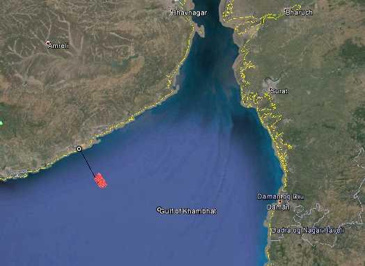
14 Foundation types OWF Gujarat 14

15 Foundation types Selection OWF Gujarat Water depth -> 14 to 18 m w.r.t. LAT Wind turbine MW class -> 3 to 6 MW Costs Ground conditions -> Clay and sand Installation vessels availability Local fabrication facilities 15
16 Foundation types Selection OWF Gujarat Criterion Gravity Jacket Monopile Water depth 0-40-> > > + Wind turbine MW class Costs Ground conditions Installation vessel Local fabrication Sum
17 Wind turbine technology Available Turbine Models Rated Power (MW) IEC Class Rotor diameter (m) MHI Vestas V MW 9.5 IEC S 164 MHI Vestas V MW 3.3 IEC IB 112 Senvion 6.3 M IEC S 152 Siemens SWT IEC IB 154 Siemens SWT IEC IB
18 Wind turbine technology Risks Project-Price grows with risk: New Models mean higher risk OEM's inexperienced with offshore environment mean higher risk Adapted onshore models mean higher risk => Lower Project-Risk with proven offshore wind turbines e.g. Siemens 6MW, Siemens 4MW, MHI Vestas 3 MW 18
19 Wind turbine technology Selection OWF Gujarat Reference Turbines Rated Power (MW) Hub Height (m) Rotor diameter (m) Generic 6 MW Generic 3 MW


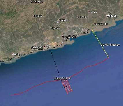
20 Wind turbine technology Layout OWF Gujarat 6 MW: 3 x 11, 1500 x 1000 m 3 MW: 3 x 22, 1500 x 500 m 20
21 Layout Optimization Increased distance between turbines => reduced wake loss and higher cable costs 2 lines of turbines compared to 3 lines => reduced wake loss and higher cable costs. 21

22 3. Introduction to foundation design I do not want my house to be walled in on all sides and my windows to be stuffed. I want the culture of all lands to be blown about my house as freely as possible. But I refuse to be blown off my feet by any Mahatma Gandhi 22
23 Introduction to foundation design Design basis Codes and standards Foundation concept Design lifetime and further Employer's requirements Design conditions Soil conditions Environmental conditions: water depths and water levels wind, typhoons waves, currents earthquakes temperatures etc. Design processes, methodologies and loads Compiled in "Design Basis" document 23
24 Introduction to foundation design Codes and standards DNVGL family of standards: Governing standard: DNVGL-ST-0126 Standards for loads: DNVGL-ST-0437 (alternatively IEC /-3) Guidelines for steel design: DNV-RP-C202: Buckling Strength of Shells DNVGL-RP-C203: Fatigue design of offshore steel structures Corrosion: DNVGL-RP-0416 Grout: DNVGL-RP
 and transition piece (TP) Grouted connection between MP and TP Secondary Steel components of the foundation, also referred to as appurtenances or Secondary Steel Scour")
25 Introduction to foundation design Basic components Wind turbine generator (WTG): Rotor-Nacelle-Assembly (RNA) WTG tower WTG foundation or sub-structure: Primary structures, also referred to as Primary Steel: monopile (MP) and transition piece (TP) Grouted connection between MP and TP Secondary Steel components of the foundation, also referred to as appurtenances or Secondary Steel Scour protection on the seabed 25
26 Introduction to foundation design Basic components - foundation Structural components from design point of view: Primary Steel: These are components which are participating in the overall integrity of the structure or which are important for operational safety. Structural parts where failure will have substantial consequences. Secondary Steel: These are components of no significance for the overall integrity of the structure. Structural parts where failure will be without significant consequence. Special Steel: These are components which are essential to the overall integrity of the structure and exposed to particularly arduous conditions. Structural parts where failure will have substantial consequences and are subject to a complex stress condition. Special structural members are a subset of the Primary Steel. 26
 FLS (over the design life time) NFA (limits for WTG, to avoid resonance) ALS (e.g. ship impact) SLS (e.g. deformation limits) 27")
27 Introduction to foundation design Design process Dynamic system Wind and turbulence on the WTG Wave loads acting on the foundation Design checks: ULS (50-year wind and wave) FLS (over the design life time) NFA (limits for WTG, to avoid resonance) ALS (e.g. ship impact) SLS (e.g. deformation limits) 27
28 Introduction to foundation design Design process load iteration Iterative process 28

29 Introduction to foundation design Appurtenances External: Access system: Boat landing External resting platforms Access ladders External working platform / service platform Technical: Corrosion protection components Cable protection system Grout lines etc. 29

30 Introduction to foundation design Appurtenances Internal: Bolting platform Switch gear platform Airtight deck Internal working platform Internal ladders 30

31 Introduction to foundation design Appurtenances Access system Boat landing External resting platforms Access ladders 31

32 Introduction to foundation design Appurtenances Service platform 32

33 Introduction to foundation design Appurtenances Airtight deck 33

34 Introduction to foundation design Appurtenances Internal working platform 34


35 Introduction to foundation design Appurtenances Corrosion protection system ICCP GACP 35
36 5. Basis for design The site conditions for OWF Gujarat 36

37 Basis of Design Overview Codes and standards -> DNVGL family of standards and guidelines Foundation concept -> Monopile with grouted connection Design lifetime Design conditions 37 Soil conditions Environmental conditions: water depths and water levels wind, typhoons waves, currents earthquakes temperatures etc. Design processes, methodologies and loads
38 Basis of Design Design lifetime Operation lifetime -> 25 years Installation period -> 6-12 months Commissioning of WTG -> 6 months Decommisioning -> 6 months Design lifetime -> 27 years 38

 Clay (Stiff)")
39 Basis of Design Soil conditions Clay (Soft) Clay (Stiff) Sand 39
40 Basis of Design Environmental conditions water depths and levels Water depths range between 14 an 18 m w.r.t. LAT for OWF Gujarat -> 16 m w.r.t. LAT Extreme values for typhoon conditions: Return period (years) 50 Highest sea water level (m LAT) Storm surge (m) 3.26 Significant wave height Hm0 (m) 9.5 Extreme (design) wave height (m) 17.7 Extreme (design) wave crest (m) 13.8 Highest wave level (m LAT)
41 Basis of Design Wind conditions wind speeds 41


42 Basis of Design Wave conditions normal conditions Significant wave height Peak wave period 42

43 Basis of Design Earthquakes 43

44 Basis of Design Summary Design lifetime: 27 years Environmental conditions Water Depth: 16m Highest sea water level: +7.80m LAT Wind and wave loads: according to Metocean study Maximum design wave level: m LAT Splash zone: -1.50m to +7.00m LAT Marine growth: according to ISO :2005 Earthquakes: 1 time bottom diameter of MP added to pile length Scour protection assumed Design loads: FLS and ULS Soil conditions
45 5. Advisory Foundation Design 45
46 Advisory Foundation Design Concept Design Monopile foundation recommended for the site Most common foundation type in offshore wind farms Suitable for a wide variety of soil conditions Rapid fabrication and installation Lower costs compared to other foundation types Challenges are Heavy lift crane for installation Hydraulic hammer for installation Fabrication facilities for huge piles and TPs 46
47 Advisory Foundation Design Main Features Conical grouted connection between MP and TP Interface level between TP and Tower at +24m LAT Top of MP at +6 m LAT Bottom of TP at -4m LAT 47
48 Advisory Foundation Design Results ULS and FLS design checks fulfilled. NFA: Turbine Model [-] 3 MW 6 MW Frequency (ULS model/lb) [Hz] Frequency (FLS model/be) [Hz] Frequency (Upper Bound/UB) [Hz]
49 Advisory Foundation Design Dimensions 49 Turbine model [Unit] 3 MW 6 MW Mass of TP [MT] Length of TP [m] Top diameter of TP [m] Bottom diameter of TP [m] Wall thickness of TP [mm] Mass of MP [MT] Length of MP [m] Embedment length of MP [m] Top diameter of MP [m] Bottom diameter of MP [m] Wall thickness of MP [mm] Length of cylindrical section of MP [m] Length of conical section of MP [m] 16 16
50 Thank you very much for your attention! Any questions? 50