August 31, Myrna Webber Managing Broker 201 West Springfield Ave., 11 th Floor P.O. Box 140 Champaign, IL
|
|
|
- Ethan Lang
- 5 years ago
- Views:
Transcription

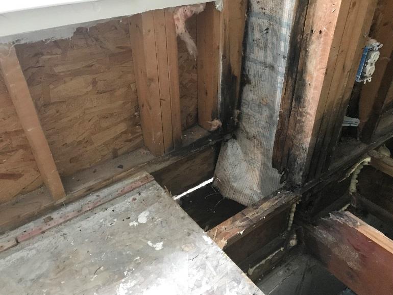
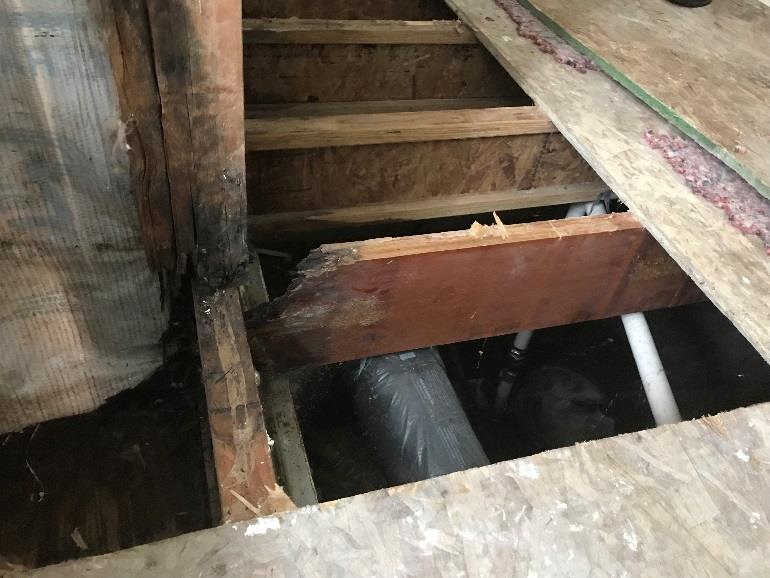
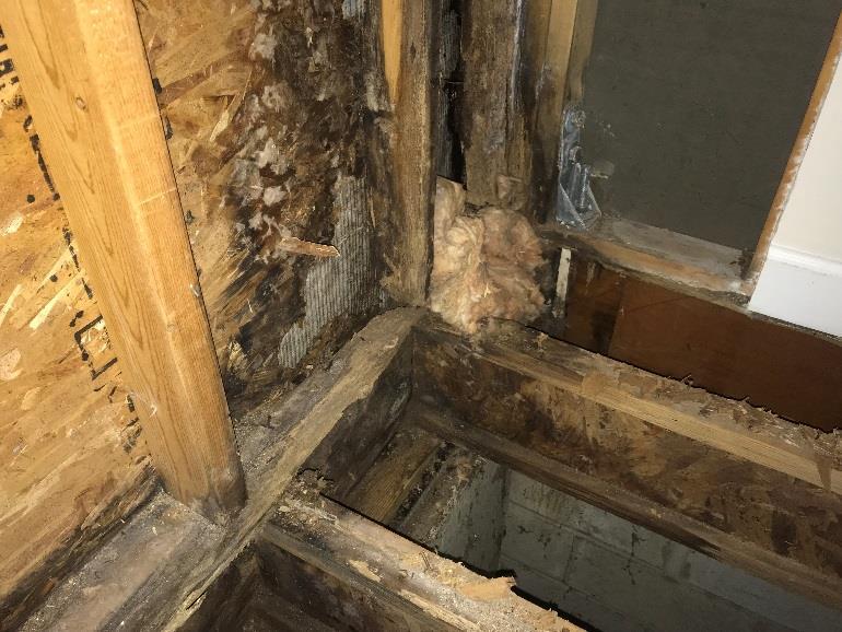
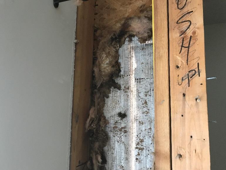
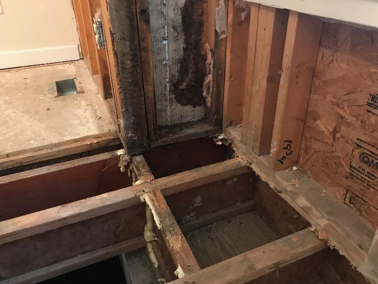
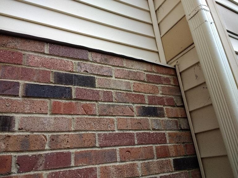
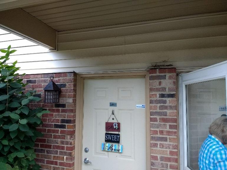
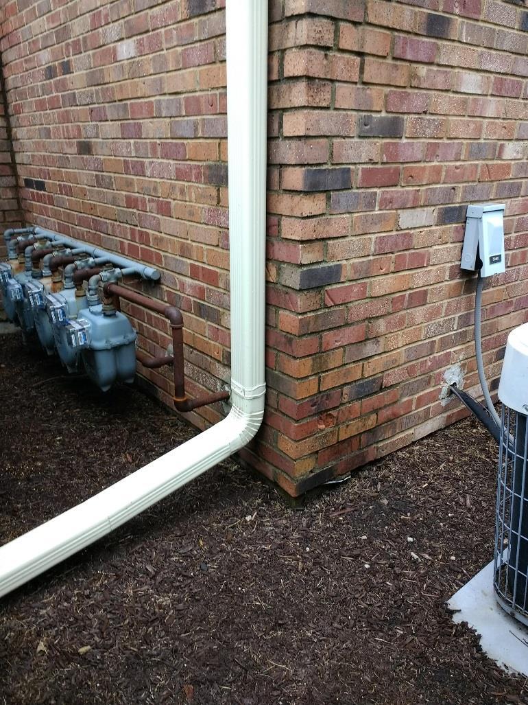
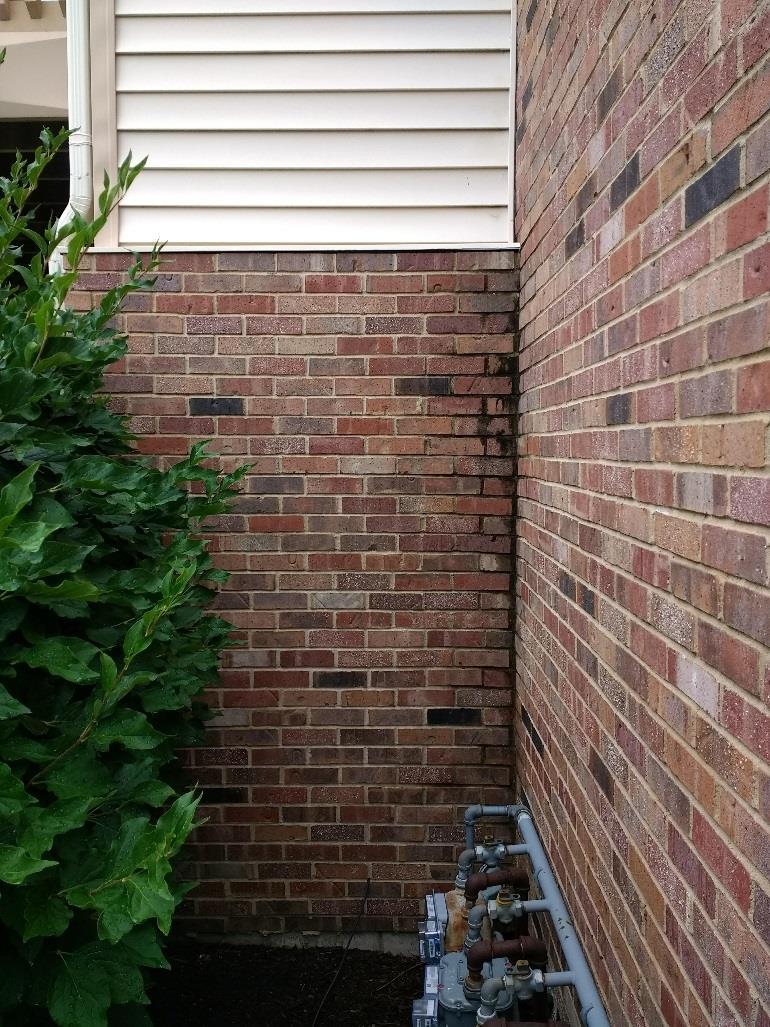
1 221 1 W est Bradley Aven ue Cham pai gn, Illinois p f w.com nn avi gation.com August 31, 2018 Myrna Webber Managing Broker 201 West Springfield Ave., 11 th Floor P.O. Box 140 Champaign, IL RE: Cobblefield Point Building Envelope Study Dear Ms. Webber, On August 24, 2018, Farnsworth Group visited the Cobblefield Condominiums at 3858 Thornhill Circle in Champaign, IL to investigate a number of building envelope concerns. During our site visit, we witnessed conditions in two vacant units on the west side of the property. The primary concern is that several units in the condominium complex have experienced structural degradation and moisture infiltration into the interior of the units. Upon entering the units, we observed that the Property Management had completed some partial deconstruction of the exterior walls and floors for investigation. In the first unit we visited, a portion of the drywall was removed on the exterior of the wall. In addition, the plywood subfloor and finished floor were removed in the same areas the drywall was removed. Any insulation in the stud cavities of the exterior walls was also removed. A few items shall be documented and noted: On the day we visited the site, it was cloudy, rainy, and mild. Record drawings for the buildings were not available for review. We only investigated areas visible at the time of our visit. We did not perform any deconstruction of the wall during our visit. We did not study any other areas except the base of the wall. Findings Refer to appendix A for photos. Exterior side of the wall: o o o The brick was saturated at inside corners and along the base of the wall. The running bond brick veneer extends from the top of the foundation wall to the top of the first floor. The top of the brick wall is a running course of brick that does not appear to be sloped. The top of the masonry wall has a prefinished metal flashing that wraps over the front of the top brick course, extends horizontally over the top of the wall, and turns upward to tuck behind the vinyl siding. The J-channel and starter course for the vinyl siding rests E N G I N E E R S A R C H IT E C T S S U R V E Y O R S S C IE N T I S T S
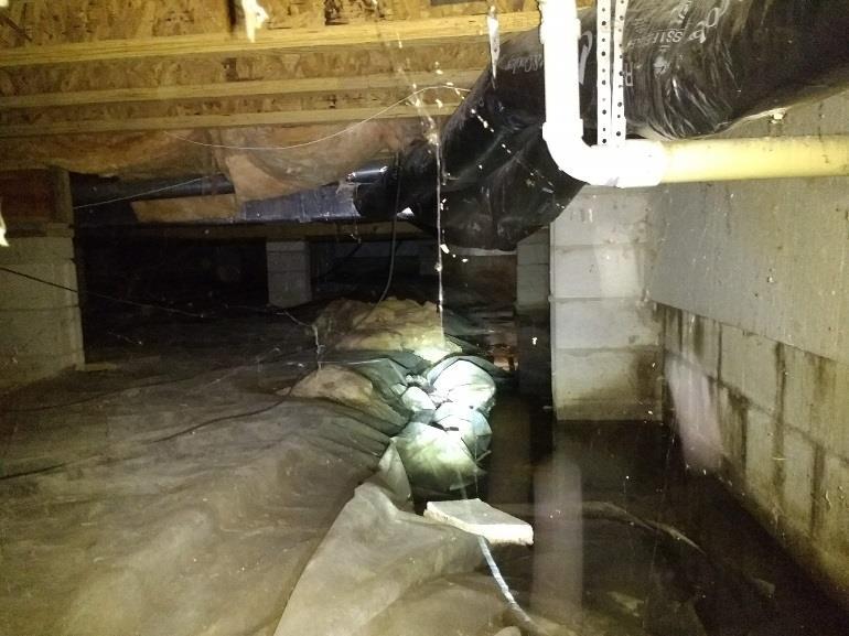
2 directly on top of the flashing. In many places, the flashing has been bent and weathered in such a manner that it has peeled upward away from the brick and no longer covers the top of the brick. o No weep holes were witnessed in the base of the wall or above openings. o No drip edge for through-wall flashing was witnessed. Interior side of the wall: o Standing water was visible in the crawl space sitting on top of the plastic barrier. In some areas, it was as deep as 3 inches or more. o Wood floor joists that make up the floor structure have severe degradation as it intersects the exterior wall. o The sill plate for the wood stud wall has severe degradation and rot. o The base of the studs shows rot and degradation. o The oriented strand board (OSB) wood sheathing on the exterior face of the wall has severe degradation and rot. In several locations, the wood has completely rotted away. o The air barrier (Tyvek) membrane on the exterior face of the OSB sheathing is still intact. o A portion of the air barrier membrane was cut away at the base of the wall to reveal the backside of the brick. Thus, no flashing was present at the base of the wall. o An air gap was present between the exterior sheathing and the back face of the brick veneer. This gap is +/- 1 inch. o A portion of the exterior wall in the living room and bedrooms bumps out and extends beyond the foundation wall. The floor joists cantilever over the foundation wall and form the base of the bump out. The bottom of the floor joists are sheathed with plywood to seal off the base of the bump out from weather. These floor joists and plywood have degradation and rot. In fact, daylight was visible between the plywood and the bottom of the joists. o A vertical transition between siding and the brick occurs at the inside corner between the bump out and main portion of the exterior wall. The OSB sheathing, studs, sill plate and other wood framing members were rotten, degraded, or non-existent. In fact, daylight was visible between the brick and siding joint. Based upon the findings above, we recommend the following construction practices should have occurred at the time of construction: The top of the masonry wall would have a cast stone cap, rowlock course, or similar masonry to provide positive drainage toward the exterior of the wall. This top course should be sloped toward the exterior a minimum of 15 degrees. Non-ferrous metal flashing would be installed at all interruptions in the masonry cavity. This includes window and door heads, top of wall cap, structural connections such as decks, etc. Flashing would be installed behind and underneath the top cap of the wall. The flashing would extend from the back of the cavity, through the brick, and terminate at the exterior with a hemmed edge. The vertical leg of the flashing should attach directly to the wood sheathing and would have the waterproofing membrane lap over the top of the flashing. Non-ferrous metal flashing would be installed at the base of the wall. The flashing would extend from the back of the cavity, through the brick, and terminate at the exterior with a hemmed
3 edge. The vertical leg of the flashing would attach directly to the wood sheathing and would have the waterproofing membrane lap over the top of the flashing. At all interruptions in the masonry cavity and at the base of the wall, cavity drainage material would be installed to keep the drainage plane and cavity clear of mortar droppings. Weep holes spaced at 24 inches on center would be installed at the base of all flashing. The foundation wall would extend to the exterior edge of the bump out to eliminate exposure of wood framing to the exterior. Install waterproofing membrane behind brick. This could be asphaltic felt paper or preferably a spray-applied membrane. Install flashing between the siding and the brick vertical joint with non-ferrous metal flashing that is L shaped. Size gutters and downspouts appropriately per code required rain event. Install kickout flashing and rainwater diverters on the gutters. Refer to Appendix B for Technical Notes on Brick Construction which describes standard practices for brick veneer installation and construction. If you should have any questions regarding the information above, please contact me at (217) Sincerely, FARNSWORTH GROUP Scott Burge, AIA Architect Attachments: Appendix A - Photos of Existing Conditions Appendix B The Brick Industry Association Brick Veneer / Wood Stud Walls

4 APPENDIX A

5
6

7 APPENDIX B TECHNICAL NOTES on Brick Construction 1850 Centennial Park Drive, Reston, Virginia November 2012 Brick Veneer / Wood Stud Walls Abstract: This Technical Note deals with the prescriptive design of anchored brick veneer over wood stud backing in new construction. The properties of the brick veneer/wood stud system are described, which lead to design considerations. Selection of materials, construction details and workmanship techniques are also included. Key Words: air space, anchors, brick, flashing, foundations, lintels, veneer, weeps, wood frame. SUMMARY OF RECOMMENDATIONS: Support: Provide a noncombustible foundation to support veneer Where vertical support is provided by wood construction, provide steel angles properly attached to or supported by wood framing Veneer Height Limitations: For residential construction (IRC), do not exceed height listed in Table 1 For commercial construction (IBC) see Additional Requirements for Buildings Covered by the IBC and the Wood chapter of IBC Air Space: Maintain a minimum 1 in. (25 mm) air space* Where corrugated anchors are used, maintain a maximum 1 in. (25 mm) air space Do not exceed 4½ in. (114 mm) between back of brick and sheathing unless anchors are rationally designed Completely fill the air space below wall base flashing with grout or mortar Where continuous insulation is placed between the veneer and backing, maintain 1 in. (25 mm) between the back of the brick and the face of the insulation * An air space is allowed to be a 1 in. (25 mm) nominal dimension in the IRC and a 1 in. (25 mm) specified dimension in the IBC to account for construction tolerances. Flashing: Install above grade at the wall base and extend to or beyond face of brickwork Extend base flashing at least 8 in. (203 mm) vertically Place at all points where air space is interrupted and at other locations where water removal is desired, such as under sills and copings Where flashing is discontinuous, form dams by turning ends up at least 1 in. (25 mm) into a head joint Weeps: Open head joint weeps at 24 in. (610 mm) o.c. maximum are preferred Space wicks or weep tubes no more than 16 in. (405 mm) o.c. Anchors: Do not space anchors more than 32 in. (813 mm) horizontally and 24 in. (610 mm) [IRC] or 25 in. (635 mm) [IBC] vertically Where corrugated metal anchors are installed, their minimum thickness should be No. 22 U.S. gage (0.03 in. [0.76 mm]) Provide additional anchors within 12 in. (305 mm) of openings larger than 16 in. (406 mm) at a maximum spacing of 3 ft (0.91 m) o.c. Provide at least one anchor for each 2.67 sq ft (0.25 m²) of wall area Where veneer is laid in stack bond, install single wire joint reinforcement Secure anchors to the studs through the sheathing, not to the sheathing alone Fasten anchors with corrosion-resistant 8d common nail or equivalent, and within ½ in. (13 mm) of the 90 degree bend of corrugated anchors Seismic Areas: For commercial construction (IBC) in Seismic Design Category (SDC) C or above, isolate sides and top of veneer from structure For buildings in SDC D or above and townhouses in SDC C, reduce maximum wall area per anchor by 25 percent For buildings in SDC D, fasten anchors with 8d ring shank nail or fastener with equivalent pullout strength For commercial construction (IBC) in SDC E or above, install single wire horizontal joint reinforcement in bed joints no more than 18 in. (457 mm) o.c. vertically, and mechanically fasten to anchors High Wind Areas: For residential construction (IRC), provide one anchor for each 2 sq ft (0.25 m²) of wall area For commercial construction (IBC), reduce maximum wall area per anchor by 30 percent; space anchors no more than 18 in. (457 mm) horizontally and vertically; and place additional anchors within 12 in. (305 mm) of openings larger than 16 in. (406 mm) at a maximum spacing of 24 in. (610 mm) o.c. Rationally design commercial construction (IBC) when wind pressure exceeds 55 psf (2.63 kpa) or building height exceeds 60 ft (18.3 m) Lintels: For residential construction (IRC), use sizes listed in Table 2 or a 5 (vertical leg) by 3½ by 5 16 in. (127 by 89 by 8 mm) steel lintel installed in accordance with Figure 6 Size horizontal leg to support a minimum of two-thirds the thickness of the brick wythe Provide at least 4 in. (102 mm) bearing at each end of lintels Water-Resistive Barrier: Install No. 15 asphalt felt, building paper, house/building wrap or other approved water-resistive barrier over sheathing Mortar: For typical veneer applications, use Type N mortar complying with ASTM C270 Where basic wind speed exceeds 110 mph (177 km/h), use Type S mortar 2012 Brick Industry Association, Reston, Virginia Page 1 of 18
8 INTRODUCTION The brick veneer/wood stud wall system offers several advantages over other cladding systems. The system demonstrates superior performance in many of the specific areas of concern for designers, contractors and property owners, such as attractive appearance, high resistance to water penetration, low thermal transmission rate, ease of construction and low maintenance. In addition, the brick veneer provides a fire rating, reduces exterior noise transmission and resists damage from abrasion and flying debris. Dating to the Colonial era, the brick veneer/wood stud wall system has evolved into a successful construction method used in residential and light commercial structures. Buildings using this wall system are often designed with overhangs, eaves and gutters to help protect the wall assembly from wind-driven rain. Air Space Water-Resistive Barrier Wood Studs 8d Nail Veneer Anchor Weeps Flashing Foundation Figure 1 Brick Veneer/Wood Stud Wall Anchored brick veneer with wood stud backing typically consists of a nominal 3 or 4 in. (76 or 102 mm) thick exterior brick wythe attached to a wood frame with corrosion-resistant metal anchors and a prescribed air space between the veneer and the backing system, as shown in Figure 1. It is considered an anchored masonry veneer wall system by construction codes. An anchored masonry veneer is attached to and laterally supported by its backing through anchors and supported vertically by the foundation. The design of veneer ignores the brickwork s resistance to lateral loads and assumes the transfer of out-of-plane loads directly to the backing. Brick veneer with wood stud backing is used in residential as well as commercial applications and consequently may be subject to provisions of either the International Residential Code (IRC) [Ref. 3] or the International Building Code (IBC) [Ref. 2]. In this Technical Note, general design requirements and considerations that apply to construction governed by the IRC are discussed first, followed by unique or additional requirements for buildings covered by the IBC. The IBC references provisions of the Building Code Requirements for Masonry Structures (TMS 402/ACI 530/ASCE 5) [Ref. 10] with a few modifications. Table 3 provides a summary of differing requirements for brick veneer/wood stud walls found within the IBC and IRC. The proper design, detailing and construction of anchored brick veneer walls ensure that they function as complete systems. It is important to understand that the failure of any part of the system, whether in design or construction, can result in improper performance of the entire system. Satisfactory performance of brick veneer/wood stud walls is achieved with the following: (1) an adequate foundation; (2) a sufficiently strong, rigid, well-braced backing system; (3) proper attachment of the veneer to the backing system; (4) proper detailing; (5) the use of proper materials; (6) good workmanship in construction; and (7) proper maintenance, as required. Other Technical Notes in this series cover brick veneer with different backing systems. PROPERTIES OF BRICK VENEER/WOOD STUD WALLS Moisture Resistance Anchored brick veneer wall assemblies are typically constructed and classified as drainage walls. Walls of this type provide good resistance to rain penetration. The air space behind the brick wythe permits water that penetrates the veneer to drain down the back of the brickwork and be channeled out via flashing and weeps without wetting the rest of the wall assembly. It is essential to maintain the air space between the brick veneer and the backing to prevent the transmission of moisture and to ensure proper drainage. The protection provided by roof overhangs and relatively low wall heights characteristic of most structures using brick veneer on wood stud backing also aids in reducing water penetration. Buildings without some of these protection features may require design and detailing beyond the recommendations found herein. For additional information regarding water penetration resistance, see the Technical Notes 7 Series. Brick Industry Association TN 28 Brick Veneer/Wood Stud Walls Page 2 of 18
9 Thermal Performance Batt insulation is typically placed between studs to provide the primary resistance to thermal transmission; however, wood studs act as thermal bridges, reducing the effectiveness of the batt insulation. Continuous insulation is often placed within an enlarged air space to improve thermal resistance. Brick veneer wall assemblies also incorporate an air space and have thermal mass characteristics that improve their resistance to heat loss or gain. The air space increases the resistance of the wall system to heat transmission by providing a thermal separation between the brick wythe and other system components. The thermal mass of the brickwork allows it to store and slowly release heat over time, which can lower and delay peak heating and cooling loads. For this reason, some energy codes and standards require less insulation in walls meeting minimum requirements for thermal mass. For further information regarding the thermal resistance of brick assemblies, refer to the Technical Notes 4 Series and to the ASHRAE Handbook [Ref. 1]. Fire Resistance Brick veneer wall assemblies with wood stud backing routinely attain fire ratings of up to 2 hr. A nominal 4 in. (102 mm) brick wythe alone provides a 1 hr fire resistance rating for the exterior surface of the wall. The wood studs are typically protected from fire on the inside by fire-rated gypsum board, which can be layered to provide the required rating. The UL Fire Resistance Directory [Ref. 12] includes a 2 hr fire-rated brick veneer assembly with wood stud backing (U302) and two 1 hr assemblies (U356 and U371). See Technical Note 16 for additional information on fire resistance and a method for calculating the fire resistance of an assembly. Acoustical Properties Brick veneer walls with continuous air spaces are well suited as sound insulators and reduce sound transmission by multiple means. The hard surface of the brickwork reflects the vast majority of sound waves, and the mass of the brickwork absorbs a portion of the sound energy. The remaining sound energy that makes its way through the brick wythe is dampened by the air space separating the brickwork from the remainder of the wall assembly. With only anchors bridging the air space, a minimal amount of sound energy is transmitted to interior wall elements. These properties make brick walls effective at resisting the passage of noises commonly in the range of speech, typically measured by the Sound Transmission Class (STC) rating, as well as insulating spaces against lowfrequency outdoor noises such as traffic, aircraft, etc., as measured by the Outdoor-Indoor Transmission Class (OITC). Brick veneer walls with wood stud backing similar to the one shown in Figure 1 have achieved measured STC values as high as 56 [Ref 8]. Testing has established that a nominal 4 in. (102 mm) wythe of brick alone can achieve an STC rating of 40 or higher. In addition to testing, the STC rating of brick veneer can be estimated based on its weight, in accordance with Standard Method for Determining the Sound Transmission Class Rating for Masonry Walls, TMS 302 [Ref. 9]. OITC, another measure of sound insulation, is receiving growing attention, particularly for exterior walls. OITC values around 40 can be expected for brick veneer walls with wood stud backing [Ref. 5]. Additional information on sound transmission can be found in Technical Note 5A. Aesthetics Brick is available in a large variety of colors, textures, glazes and coatings. In addition, many sizes are manufactured, as well as special shapes that can be used to create truly unique features. Add to this the ability to use multiple bond patterns, the use of colored mortars and interesting masonry detailing, and the creative possibilities are nearly endless. For further information on sizes and patterns, refer to Technical Notes 10B and 30. Ease of Construction The wood studs and exterior sheathing of a brick veneer/wood stud wall can be constructed prior to laying the brick veneer wythe. This allows the building to be closed in and placed under roof quickly. Thus, interior work can begin with brick masonry construction following at a convenient time. Further, other trades can be scheduled to work and not interfere with the mason. Care should be taken to ensure that other wall system elements are not compromised prior to installation of the brickwork. Brick Industry Association TN 28 Brick Veneer/Wood Stud Walls Page 3 of 18
10 STRUCTURAL DESIGN CONSIDERATIONS Vertical Support and Veneer Height Anchored brick veneer carries its own weight and transfers it to a foundation or other vertical support. The type of vertical support and the Seismic Design Category (SDC) of the structure largely determine the maximum height of brick veneer permitted by building codes. Height limits are imposed because of differences in movement resulting from wood shrinkage and brick expansion. Table 1 summarizes the height limits and related criteria within the IRC for brick veneer above noncombustible foundations. For height limits of brick veneer in other than one- and two- family dwellings, see Additional Requirements for Buildings Covered by the IBC. Building Type TABLE 1 Height Limits for Anchored Brick Veneer above Noncombustible Foundations (IRC) Seismic Design Category (SDC) Number of Stories Maximum Height, 1 ft (m) Maximum Nominal Veneer Thickness, in. Maximum Veneer Weight, psf (kg/m²) All Buildings A,B or C 1, 2 or 3 30 (9.14) 5 50 (240) One- and Two-Family Detached Dwellings 2 D (9.14) 4 40 (195) 1 or 2 20 (6.10) (195) D 1 1, 2 or 3 20 (6.10) (195) D 2 1 or 2 20 (6.10) (195) 1. An additional 8 ft is permitted for gable end walls. 2. Cripple walls (framed walls between the foundation and first floor framing) are not permitted. 3. The veneer is permitted to reach 30 ft (9.14 m) in height where the lower 10 ft (3.05 m) has a backing of concrete or masonry wall. Wood Foundations. Preservative treated wood foundations should be used only in buildings that have no more than two floors, as dictated by the IRC. For buildings in SDC D and above, wood foundations must be designed by an engineer. Other Wood Support Conditions. Brick veneer that is to be supported by other structural wood elements is subject to additional restrictions. These requirements apply to conditions such as where a lower roof abuts a taller brick veneer wall, (e.g., a one-story garage abuts a two-story residence) and where it is not possible or practical to transfer the weight directly to the foundation. Veneer supported by wood construction must be isolated from veneer supported by the foundation with an expansion joint. The deflection of wood members supporting brickwork should not exceed L/600 or 0.3 in. (8 mm). Two methods for support on wood construction are prescribed by the IRC: support by steel angle and support by roof construction. In no case should the brick bear directly on roof sheathing. In each case, up to 12 ft-8 in. (3.9 m) of exterior brick veneer weighing 40 psf (195 kg/m²) or less may be supported if two-thirds of the brick thickness bears on the steel angle, a minimum 1 in. (25 mm) air space is maintained, and flashing is in accordance with Figure 2. Where the slope of the roof construction is 7:12 or more, steel plates at least 3 by 3 by ¼ in. (76 by 76 by 6 mm) must be welded to the angle at 24 in. (610 mm) o.c. to prevent sliding of the brickwork. Support by Steel Angle. A steel angle with dimensions of at least 6 (vertical leg) by 4 by 5 16 in. (152 by 102 by 8 mm) and bolted to wood studs as required is designed to support the veneer weight, including the effects of deflection and rotation. The angle must be attached with a minimum of two 7 16 in. (11 mm) diameter by 4 in. (102 mm) long lag screws to double 2 4 wood studs spaced at a maximum of 16 in. (406 mm) o.c. A gap of not less than 1 16 in. (1.6 mm) must be maintained between the bottom of the steel angle and the underlying construction according to the code, although a ¼ in. (6 mm) gap is recommended. Support by Roof Construction. A loose steel angle placed directly on top of roof construction may be used to distribute the load of the brickwork to the wood members below when the roof is supported by triple 2 6 wood rafters sized to support the weight of the masonry and attached to wall studs. The wood rafters deflection must be less than L/600. The rafters must be anchored to each other using two 10d nails at every stud spacing and to the vertical stud construction with a minimum of three ⅝ in. (16 mm) diameter by 5 in. (127 mm) lag screws at every stud. Brick Industry Association TN 28 Brick Veneer/Wood Stud Walls Page 4 of 18
11 Veneer Anchor Water-Resistive Barrier on Exterior Sheathing Steel Angle Weep Counter Flashing Base Flashing Veneer Anchor Water-Resistive Barrier on Exterior Sheathing Steel Angle Weep Counter Flashing Base Flashing Fasteners Roof Framing Triple Rafters Lag Screws (a) Support by Steel Angle Figure 2 (b) Support by Roof Construction Wood Stud Deflection Criteria Wood studs must provide adequate out-of-plane support for all loads imposed on the wall system. Wood stud sizing and spacing is dictated using appropriate design codes for wood along with provisions from the IRC or IBC. Brick veneer/wood stud walls have been used successfully on one- and two-family residential construction for many years due to the short span of the studs and multitude of interior perpendicular walls. For walls with taller stud spans or no intersecting walls, a deflection analysis following the L/240 IBC limit for the maximum deflection of exterior wall structural members supporting brittle finishes is prudent. This limits the crack size due to loading, thereby reducing the potential for water penetration. Seismic Requirements Building codes have included increasingly stringent provisions for brick veneer buildings in higher seismic categories. In the IRC, brick veneer in SDC D 0, D 1 and D 2 has more restrictive height limits, maximum thickness and weight limits, in addition to the requirements in Table 1 and those discussed earlier. The maximum wall area each veneer anchor can support in SDC D 0, D 1 and D 2 and townhouses in SDC C is limited to 2 sq ft (0.2 m²). Anchors in SDC D must be fastened with an 8d ring shank nail. The IRC requires buildings in SDC E to meet the applicable requirements of the IBC, discussed later in Additional Requirements for Buildings Covered by the IBC. High Wind Requirements Where the basic wind speed exceeds 100 mph (49 m/s), brick veneer attachment must resist the component and cladding loads specified in the IRC, Building Planning chapter, adjusted for height and exposure. The IRC limits the maximum wall area supported by each anchor in areas where the wind pressure exceeds 30 psf (1.44 kpa) to 2 sq ft (0.2 m²). For buildings to which the IRC is not applicable, see Additional Requirements for Buildings Covered by the IBC. Wall Bracing of Wood Frame Construction Bracing is needed to stiffen wood-framed walls and to increase their resistance to lateral loads. The required length of braced wall lines and hold-down force of connectors increases with higher wind speeds and SDCs and is also dependent on the story of a structure being considered, alignment of braced wall panels and the type of brace selected. Although these requirements do not impact the brick veneer and are beyond the scope of this Technical Note, they may dictate wall location, opening locations or allowable sheathing materials. More information on wall bracing can be found in the IRC or in other references [Refs. 3 and 6]. Brick Industry Association TN 28 Brick Veneer/Wood Stud Walls Page 5 of 18
12 Water-Resistive Barrier on Exterior Sheathing Veneer Anchor Air Space Flashing Weep Filled Cavity Beneath Flashing Veneer Anchor Water-Resistive Barrier on Exterior Sheathing Flashing Weep Veneer Anchor Water-Resistive Barrier on Exterior Sheathing Flashing Weep Filled Cavity Beneath Flashing (a) CMU Foundation/Wood Floor (b) CMU Foundation/Slab on Grade Foundation Detail (c) Concrete Foundation/Slab on Grade Figure 3 Foundation Detail Isolation Joint Isolation Joint DETAILING Foundations for Brick Veneer Typical foundation details for brick veneer are shown in Figure 3. Although the support of brick veneer on wood foundations is permitted, concrete and masonry foundations or other noncombustible structural supports, such as attached steel angles, are recommended. At least two-thirds of the brick wythe thickness should be supported on the foundation. Foundations must extend beneath the frost line as required by the local building code. Design of the foundation should consider differential settlement and the effect of concentrated loads, such as those from columns or fireplaces. Appropriate drainage must be provided in order to maintain soil bearing capacity and to prevent washout. Brickwork Below Grade. Brickwork should extend below grade only when special provisions are made in detailing and construction to minimize water penetration. Since base flashing is required to be installed in the first course of masonry higher than finished grade above the foundation, as shown in Figure 3, any space below the base flashing should be completely filled with grout or mortar to minimize water penetration. Anchors within the grout- or mortarfilled space should be located according to the same spacing as the brick veneer above grade. The finished grade should be sloped away from the wall to provide positive drainage. The IRC and IBC do not explicitly address brick veneer below grade. To avoid extending brick veneer below grade, the brick shelf in the foundation may be constructed above the final grade. If brick veneer is desired to be below grade in Northern climates, then the soil immediately adjacent to the brickwork should provide adequate drainage. If the soil does not drain well, then a French drain may be installed between the soil and the wall, consisting of a gravel fill with a fabric filter surround and a drain pipe or tile below, sloped a minimum of ⅛ in./ft (10 mm/m). Alternatively, a drainage medium may be installed on the surface of the brickwork below grade, such as a drainage mat or a drainage board. Bond Breaks. Because brickwork expands and concrete foundations shrink, differential movement will cause shearing stresses to develop when these materials are bonded together. Bond breaks help to relieve the stresses caused by these movements between the brick veneer and the supporting foundation. Flashing at the base of the wall between the veneer and the foundation provides a sufficient break in the bond, as shown in Figure 3b. Brick Industry Association TN 28 Brick Veneer/Wood Stud Walls Page 6 of 18
13 Sheathing and Water-Resistive Barrier An exterior grade sheathing or insulation material is usually installed on the exterior side of the studs. A waterresistive barrier is required to be placed over the studs or sheathing. These membranes prevent liquid water from passing through them and should keep out any water that finds its way across the air space via anchors, mortar bridging or splashing. Examples include No. 15 asphalt felt and other materials, such as building paper and house/ building wraps. Air Space The air space behind a brick veneer provides a means to drain water that penetrates the brickwork and inhibits the direct passage of water toward the interior. The width of the air space, the distance from the back of the brick to a material on the opposite side of the air space, should not be less than 1 in. (25 mm) wide. A 1 in. (25 mm) air space is customary in residential brick veneer/wood stud walls and has been used successfully for decades. Building codes also require a minimum 1 in. (25 mm) air space but use the terms nominal or specified to describe the distance. The IRC requires a minimum air space of a nominal 1 in. (25 mm), and the IBC requires a 1 in. (25 mm) minimum air space to be specified. Nominal or specified are used in order to acknowledge the construction tolerances and other field issues associated with installing the materials that surround the air space. These issues may cause the actual dimension of the air space to measure less than 1 in. (25 mm). The most important aspect of the air space is that it creates a separation and allows any water that has penetrated the brick veneer to drain downward to flashing and exit the wall system through weeps. In many cases, residential details such as those used at foundations, window jambs and anchors may not accommodate an air space wider than 1 in. (25 mm) without modification of details or changes in product selection. One- and two-family dwellings generally have larger overhangs and lower wall heights than commercial structures, which reduces their exposure to winddriven rain. For commercial structures with brick veneer/wood stud walls, a wider air space of 2 in. (51 mm) is recommended. When corrugated anchors are used, the distance from the back of the brick to the framing must not exceed 1 in. (25 mm) since these types of anchors do not provide adequate load transfer across larger distances. This maximum is allowed to be a nominal dimension of 1 in. (25 mm) in the IRC and a specified dimension of 1 in. (25 mm) in the IBC to acknowledge construction tolerances. With other types of anchors, a 4½ in. (114 mm) maximum distance is permitted between the back of the brick veneer and the wood framing. This distance may be exceeded if the anchor size and spacing are rationally designed. In some cases, continuous insulation is used in place of sheathing or added to the exterior of the sheathing for added thermal resistance. As stated before, a 1 in. (25 mm) distance between the back of the brickwork and the face of the insulation should be provided. Consequently, accommodating the placement of continuous insulation within the air space precludes the use of corrugated anchors. Insulation should be attached to the backing by mechanical or adhesive means to ensure that it does not dislodge and block or bridge the air space. Drainage Products. Products designed to prevent mortar bridging, ensure a clear drainage space or catch mortar droppings to prevent blocking of weeps may be installed in the air space. Some products perform more than one of the functions noted above. Such products may be beneficial when a high probability of mortar falling into or bridging the air space exists, such as for multi-story brick veneer without shelf angles. However, the use of drainage products should not preclude good workmanship and an effort to keep the air space clean of excess mortar droppings. Flashing Flashing is essential to collect water that has penetrated the veneer and to direct it out of the wall through the weeps at the bottom of the air space. Flashing and weeps must be placed at all locations where the air space is interrupted, including: beneath the first course of brickwork above final grade; at points of support, such as shelf angles, lintels and structural floors; at wall and roof intersections; at the heads, jambs and sills of exterior window and door openings; at the intersection of chimneys or other masonry construction with frame or stucco walls; Brick Industry Association TN 28 Brick Veneer/Wood Stud Walls Page 7 of 18
14 under and at the ends of copings and sills; and where exterior porches, decks or stairs attach to a wall or floor assembly of wood frame construction. Flashing should extend to the exterior face of the brick veneer, with the back edge turned up at least 8 in. (203 mm) vertically. When the flashing is installed after the moisture barrier or air barrier, the flashing should be attached to the wall with a termination bar. Extending flashing beyond the face of the brickwork to form a drip is recommended. When using a flashing that deteriorates with UV exposure, a separate drip edge can accomplish this. When a drip edge is not used, the flashing should stop, or be cut, flush with the face of the wall. If drainage materials that catch mortar are placed at the bottom of the air space, then flashing at the base of the wall should extend farther up the backing. This ensures that the flashing extends above the height of the drainage material and helps deter water that migrates across mortar on top of the drainage material from entering the backing. The water-resistive barrier should lap the top of the flashing a minimum of 4 in. (102 mm). Where the flashing is not continuous, such as over and under openings in the wall, the ends should be turned up at least 1 in. (25 mm) into a head joint to form a dam. Typical flashing details are shown in Figure 3, Figure 5 and Figure 7. Weeps Weeps permit water to exit the wall and must be located in the mortar joints immediately above all flashing. Weeps must have a minimum diameter of 3 16 in. (4.8 mm) and may be spaced up to 33 in. (838 mm) o.c. However, larger, more closely spaced weeps provide better drainage and drying. Clear, open head joint weeps are preferred and should be spaced no more than 24 in. (610 mm) o.c. Noncorrosive metal, mesh or plastic screens can be installed in open head joint weeps if desired. Weeps formed with wick materials or with tubes should be spaced at a maximum of 16 in. (406 mm) o.c. Wicks used for drainage should extend horizontally along the length of the flashing and have one end extended up some distance above the anticipated level of mortar droppings. Anchors (Wall Ties) Brick veneer is supported laterally by anchors (often referred to as wall ties ) and the wood stud backing. The anchors must provide out-of-plane support while allowing in-plane movement. They should resist tension and compression resulting from forces perpendicular to the plane of the wall, but not resist shear. This permits in-plane differential movement between the frame and the veneer without causing cracking or distress. The veneer may be attached to wood studs or framing with corrugated sheetmetal anchors, sheet-metal anchors, wire anchors or adjustable anchors. More common anchors used with wood stud backing are shown in Figure 4. Anchor Selection. Corrugated anchors have historically been used to attach brick veneer to wood stud backing. However, corrugated metal anchors are Base & Vee Anchor Eye & Pintle Anchor Corrugated Anchor Wire & Screw Anchor Figure 4 Unit Anchors for Wood Backing more susceptible to corrosion than wire anchors. Adjustable wire anchors provide better load transfer and permit differential movement in taller structures. Material requirements and installation of anchors are discussed later in this Technical Note. More detailed information on anchors can be found in Technical Note 44B. Spacing. There should be one anchor for every 2⅔ sq ft (0.25 m²) of wall area. The IRC permits horizontal spacing of anchors up to 32 in. o.c. Vertical spacing of anchors shall not exceed 24 in. (610 mm) o.c. Slightly different anchor spacing requirements for buildings covered by the IBC are discussed later in this Technical Note under the heading Additional Requirements for Buildings Covered by the IBC. Both the IRC and the IBC require additional anchors around openings larger than 16 in. (406 mm) in either dimension. In this case, anchors should be located within 12 in. (305 mm) of the opening and spaced at a maximum of 3 ft (915 mm) o.c. Brick Industry Association TN 28 Brick Veneer/Wood Stud Walls Page 8 of 18
15 Lintels Except when the masonry is self-supporting, brick veneer must be supported over openings by lintels. Lintels provide support of brickwork over masonry openings by bearing on the brickwork on each side of the opening, rather than attaching to the building structure, as is the case with shelf angles. Lintels may be reinforced brick masonry, reinforced concrete masonry or steel angles. Typical residential construction details for a steel and masonry lintel are shown in Figure 5. Lintel design information may be found in Technical Notes 17B and 31B. Steel, stone or precast lintels should bear at least 4 in. (102 mm) on brickwork on each side of the opening. Lintels must be appropriately sized to carry the weight of the veneer. Prescriptive requirements within the IRC permit single lintels with maximum clear spans up to the values shown in Table 2. Alternatively, a steel lintel 5 by 3½ by 5 16 in. (127 by 89 by 8 mm) or larger can span up to 18 ft-3 in. (5.6 m) if the construction complies with Figure 6 and the following requirements, as taken from IRC Section : A minimum length of 18 in. (457 mm) of masonry veneer is provided on each side of the opening; The angle is shored for a minimum of seven days after installation of the brickwork above; Double-wire joint reinforcement, 3 16 in. (4.8 mm) in diameter must be placed in the first two bed joints above the opening and extend 12 in. (305 mm) beyond each side of the opening. Alternatively, 9 gage (0.144 in. Water-Resistive Barrier Lapped over Flashing Steel Angle Lintel Through-Wall Flashing Weep Sealant Water-Resistive Barrier Lapped over Flashing Through-Wall Flashing Weep Masonry Lintel Sealant (a) Loose Steel Lintel (b) Masonry Lintel Figure 5 Lintel Details [3.66 mm] diameter) joint reinforcement placed in the first three bed joints above the opening may be used. Splices in joint reinforcement must be lapped a minimum of 12 in. (305 mm). Reinforced Brick Lintels. Reinforced brick lintels are also a viable option. Some of the advantages of reinforced brick lintels include more efficient use of materials; inherent fire resistance; elimination of differential movement, which may occur with steel lintels and brick veneer; and no required painting or other maintenance. The design of reinforced brick lintels is addressed in Technical Note 17B. TABLE 2 Allowable Spans for Lintels Supporting Masonry Veneer Steel Lintels 1 Masonry Lintels 1 Size of Steel Angle, 2,3 No. of ½ in. or Equivalent No Story Above One Story Above Two Stories Above Reinforcing Bars in in. Reinforced Lintel ¼ 6 ft-0 in. 4 ft-6 in. 3 ft-0 in ¼ 8 ft-0 in. 6 ft-0 in. 4 ft-6 in ½ ft-0 in. 8 ft-0 in. 6 ft-0 in ½ ft-0 in. 9 ft-6 in. 7 ft-0 in Either steel angle or reinforced lintel shall span opening. 2. Long leg of the angle shall be placed in a vertical position. 3. Steel members indicated are adequate typical examples; other steel members meeting structural design requirements may be used. 4. Depth of reinforced lintels shall not be less than 8 in., and all cells of hollow masonry lintels shall be grouted solid. Reinforcing bars shall extend not less than 8 in. into the support. Brick Industry Association TN 28 Brick Veneer/Wood Stud Walls Page 9 of 18
16 MAXIMUM HEIGHT OF MASONRY VENEER ABOVE OPENING OPENING MINIMUM HEIGHT OF MASONRY VENEER ABOVE OPENING Minimum Height of Masonry Veneer above Opening, in. Maximum Height of Masonry Veneer above Opening, ft 13 < to < to height above support allowed by Section R703.7 MIN. 18 IN. 18 FEET 3 IN. MAX. ALLOWABLE SPAN MIN. 18 IN. Figure 6 Veneer Opening Requirements Steel Lintels. Steel angle lintels should be at least ¼ in. (6 mm) thick, with a horizontal leg sized to support a minimum of two-thirds the thickness of the brick wythe. A horizontal leg of at least 3½ in. (89 mm) is recommended for use with nominal 4 in. (102 mm) wide brick veneer, and a horizontal leg of 3 in. (75 mm) for use with nominal 3 in. (75 mm) wide brick veneer. Steel lintels with spans greater than 8 ft (2.4 m) may require lateral bracing for stability. Space should be provided at the end of all steel lintels to accommodate expansion of the steel. Head, Jamb and Sill Details Openings in brick veneer walls should be carefully detailed to prevent water from entering. Window frames, door frames and openings for sleeves must be attached to the backing, not to the brick veneer. Provision should be made for movement between the brick veneer and the frame or backing. Window and door flashing must be integrated with the waterresistive barrier to provide a continuous barrier to moisture and/or air infiltration, as shown in Figure 5 and Figure 7. Sills that can be installed with few or no joints, such as stone or precast sills, result in fewer opportunities for water penetration to occur. All sills should be sloped to the outside to promote drainage. A minimum angle of 15 degrees from horizontal, approximately ¼ in./in. (25 mm/100 mm) is recommended for brick rowlock sills. Refer to Technical Note 36 for further information. Slope to Drain, Min. 15 Deg. Recommended 1 Gap Min. / 4 in. (6 mm) Figure 7 Window Jamb and Sill Water-Resistive Barrier Overlapping Flashing Through-Wall Flashing Installed before Window 1 Gap Min. / 2 in. (13 mm) Overhang Min. 1 1 / 2 in. (38 mm) Sealant Joints Sealant joints are used at the perimeter of exterior door and window frames and at movement joints to resist water penetration. Sealant joints around window and door openings should be free of mortar for the entire thickness of the brick veneer and typically include a recessed, compressible foam backer rod covered by a sealant. If desired, a compressible material may be included behind the backer rod. Sealant joints around window and door openings should generally be no less than ¼ in. (6 mm) wide. A minimum of ½ in. (13 mm) is recommended between the bottom of the window frame and the top of the sill below. Refer to Technical Note 18A for further information. Brick Industry Association TN 28 Brick Veneer/Wood Stud Walls Page 10 of 18
17 Eaves A typical residential eave detail is shown in Figure 8. This detail is suggested for the area at the top of the veneer. The space between the top of the brick veneer and wood framing is necessary to accommodate movement. Larger overhangs and gutters are helpful to keep water from contacting the wall below. OTHER DESIGN CONSIDERATIONS Movement Provisions Like other building elements, brickwork will continually change in size during its life due to the combined effects of changes in temperature and moisture. Moisture expansion can continue for years, while thermal movement and mortar contraction will occur periodically, contingent upon temperature and moisture conditions. Provisions for movement, which include bond breaks (discussed above), expansion joints and joint reinforcement, are not usually required for one- and two-family dwellings; however, they may be needed in specific situations. The designer should analyze each project to determine such need. The IBC requires design and detailing of brick veneer construction to accommodate differential movement. Expansion Joints. The spacing and placement of vertical and horizontal expansion joints should be determined on a case-by-case basis. Expansion joints may be needed in brick veneer to accommodate horizontal movement in long walls, walls with returns, large openings (such as two-car garage openings), near corners and changes in support, among other conditions. These features influence how the brickwork reacts to movement in a wall. As noted above, additional expansion joints may also be needed to isolate the veneer from structural elements that impart lateral loads and veneer supported on wood construction. The placement of expansion joints and the materials used should be in accordance with the information given in the Technical Notes 18 Series. While expansion joints are rarely used in residential construction, their use should be considered in large expanses of brickwork or other areas as identified in Technical Note 18A. Horizontal Joint Reinforcement. Masonry materials subject to shrinkage stresses, such as concrete masonry, require horizontal joint reinforcement for control of cracking. Brick is not subject to shrinkage; therefore, horizontal joint reinforcement is never required in brick masonry for this purpose. It may be beneficial to use limited amounts of horizontal joint reinforcement to add strength to brick veneer above and below the corners of openings, to resist cracking from high internal stress due to movement. Energy Efficiency Brick veneer/wood stud walls must generally meet the energy efficiency requirements found in applicable building codes, energy codes or standards. The Energy Efficiency chapter within the IRC is typically used for one- and two-family dwellings. The International Energy Conservation Code (IECC) covers both residential and commercial buildings and is referenced by the IRC and the IBC. Both include specific requirements for wood-framed walls that depend primarily on the climate zone in which a building is located. A number of prescriptive and performance alternatives exist that permit a variety of materials and strategies to be used to meet energy requirements. Batt insulation between studs is sufficient to meet energy requirements for above-grade walls in some climate zones; however, better performance results from the use of continuous insulation on the exterior of the sheathing adjacent to the air space, which reduces thermal bridging through the studs. In addition, insulating the foundation supporting brickwork reduces heat loss through that area. Specific insulation requirements may exist for basement walls, crawl space walls and the perimeter of on-grade slabs, which may include the depth or extension of the insulation, how it is to be protected if located on the exterior of the foundation or exemptions in areas of heavy Soffit Frieze Board Sealant Water-Resistive Barrier Air Space Sheathing Figure 8 Eave Detail Min. 3/4 in. (19 mm) Space above Brick Veneer Anchor Brick Industry Association TN 28 Brick Veneer/Wood Stud Walls Page 11 of 18
18 termite infestations. The horizontal portion of a foundation that supports brick veneer insulation is not required to be insulated. However, there are a number of ways insulation can be installed so that this area does not provide a path for heat loss. Figure 9 shows an example of a brick veneer wood stud wall employing continuous insulation within the air space and at the foundation to optimize energy performance. The U.S. Department of Energy's Building America website [Ref. 6] is one of many online resources that provide a wealth of information related to improving the energy efficiency of both above- and below-grade walls, including specific suggestions for various climates. Condensation Water or moisture found within the stud cavity of brick veneer/wood stud walls is sometimes due to condensation. Condensation occurs at the point in the wall where water vapor within the air reaches a surface with a temperature below the dew point. If this point is within the air space, then the condensation will find its way out of the wall via the drainage system; however, if it is on the inside of the stud wall with batt insulation, it may dampen or eventually saturate the surrounding materials and reduce the R-value of the insulation or lead to mold problems. Water-Resistive Barrier on Exterior Sheathing Continuous Insulation Lap Barrier over Flashing Air Space Weep CMU Cells Insulated Rigid Insulation Floor Level above Flashing Figure 9 Continuous Insulation at Foundation A condensation analysis is helpful in determining if the potential for condensation exists in a wall. Such an analysis is not typically conducted on walls of one- and twofamily dwellings. If results indicate that it may occur within the sheathing or stud wall, then the wall design should be changed. Control of condensation can be achieved via various strategies, including improved thermal resistance, the use of continuous insulation and proper placement of vapor retarders or air barriers to control water vapor and air movement through the wall. See Technical Note 47 for a more detailed discussion of condensation control. MATERIALS Brick Brick most commonly used in anchored veneer applications conform to ASTM C216 [Ref. 4] for facing brick or ASTM C652 for hollow brick. However, building brick (ASTM C62), glazed brick (ASTM C126 and C1405) and other brick meeting minimum physical property requirements for exterior exposure may be selected as appropriate. Grade SW brick is recommended for exterior veneer applications due to its high and uniform resistance to damage caused by cyclic freezing when saturated with water. Grade MW may be used where moderate resistance to damage caused by cyclic freezing is permissible or where the brick may be damp, but not saturated, when freezing occurs. In general, masonry constructed with salvaged brick may contain less-durable units than masonry constructed with new brick. Salvaged brick and considerations for its use are discussed in detail in Technical Note 15. The IRC permits the use of second-hand (salvaged/reclaimed) brick as an alternative material when approved by the building official or when they conform to ASTM standards for new brick, as required by the IBC. Mortar Mortar should comply with the requirements of ASTM C270, Standard Specification for Mortar for Unit Masonry [Ref. 4]. Three kinds of mortar are permitted: cement-lime, mortar cement and masonry cement. A designer should select the mortar with the lowest compressive strength that is compatible with the project requirements. The compatibility between a particular brick and mortar should also be examined when determining mortar type. Type N mortar is suitable for most brick veneer, although Type S may be used. Type S mortar is recommended where Brick Industry Association TN 28 Brick Veneer/Wood Stud Walls Page 12 of 18