Modelling and testing of Thermoplastic composite parts integrating process simulation
|
|
|
- Walter Garrison
- 5 years ago
- Views:
Transcription

1 Modelling and testing of Thermoplastic composite parts integrating process simulation Coordinator: Prof. Luigi Garibaldi Tutor: Prof. Massimiliana Carello Nithin Amirth Jayasree (S221262)

2 PhD Research Activity


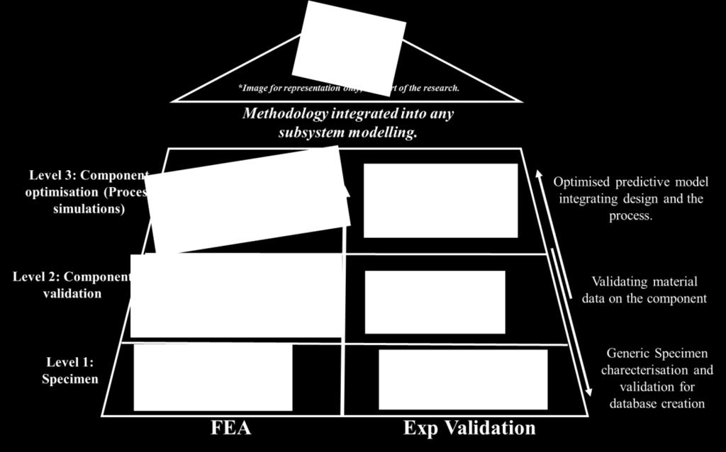
3 FE material specimens: solid and shell models Level 1: Material FEA and Experimental tests 5 Specimens tested for each behaviour


4 Level 2: Card fitting & component testing CRASURV (modified Tsai-Wu Formulation) Orthotropic plasticity hardening Based on Tsai-Wu Quadratic, interactive stress-based criterion Failure criteria not directly associated with failure modes. Do not take into account different damage mechanisms leading to failure Specimens Material Card Hashin failure criteria Failure criteria associated with failure modes. Considers non-homogenious character of composites leading to failure. Considers fibre fracture, transverse matrix cracking and shear matrix cracking. Component Force vs. Displacement Curves Four-point bending experimental test on component

 can be safely discarded for Hashin as")
5 Level 2: Card fitting optimisation & Component testing Hashin: Optimised Optmisation considerations for Hashin for better results match. Different failure modes identified and implemented for optimum fit. Shear strength increased slightly for a better fit which is validated with the flexion curve. Specimens Material Card Overall for a better composite fit a polynomial criterions such as CRASURV (Tsai-Wu) can be safely discarded for Hashin as detailed, where the composite failure can be distinguished induvidually. Component Force vs. Displacement Curves Four-point bending FEA on component


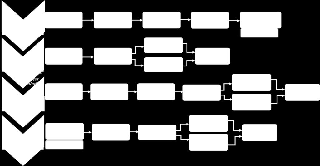
6 Process simulation Setup LEVEL 3: Process Simulations and mapping Process simulation setup to simulate the thermoforming of composite laminate Material model of blank at forming temperature: additive split between isotropic, elasto-plastic matrix and anisotropic hyper-elastic fibers. Process paramters required for process simulation: Tensile modulus and the associated tensile curve. Shear modulus and the associated shear curve. Resin parameters at forming temperature. Bending modulus. Frictional coefficients (dynamic and static).
.")

7 Tensile Tests on Fabric material 5 specimens tested. Tensile test done for fabric material (not for laminate). Tensile test results assumed to be the same for both dry fabric and laminate at melting temperature. Simulation and Tensile tests (ASTM D5035) Tensile curve fitting


8 Shear Tests: Trellis Frame Shear induced on a fabric using support on all four sides. 5 specimens tested. Done on both fabric material and laminate. Fabric testing: pure shear properties Ex Laminate: fabric shear properties + resin properties Difficult level: Complications involved in avoiding compressive forces along the edge on the specimen. Trellis Frame Laminate in thermal chamber Trellis Frame FEA


9 Shear Tests: Bias Extension Modified tensile fixture. 5 specimens tested. Inducing shear on it at the centre of a specimen oriented at 45 Tested only for fabric material (not suited for laminate). Difficult level: Complications involved in material handling, test is material dependant. Displacement at various instances: FEA Bias Specimen Bias extension test setup
10 Shear Tests: result validation Shear properties validated by comparing the shear results from Trellis and Bias extension test. Shear force normalised. Shear force vs. shear angle Shear angle obtained by Digital image correlation and the pattern validated mathematically. Done as there is no standard for both the tests and this is the best way for validation Normalized shear stress vs. shear angle for FE Input


11 Bending Test: Custom dynamic bending testing fixture Custom made components for bending tests. 5 specimens tested. Validating the bending behaviour of composite at forming temperature. (traditional bending tests impractical at forming temperature). Integration point position variation method for determining the ideal bending stiffness. Development and testing of the bending fixture Bending Fixture FEA


12 Friction tests: Custom Ply-Ply and Tool-Ply Tests Custom made components for friction tests 5 specimens tested. To obtain frictional coefficients (Static and dynamic) for Between tool and ply Between ply and ply Using a high temperature piezoelectric force sensor Easy to implement in any testing machine inside a thermal chamber for testing. Ex Ply Ply specimen

13 LEVEL 3: Thermoforming simulations Process simulation conducted to identify: Geometric non-linearities Residual stresses and strains Fabric orientation change Thickness change Buckling. Boundary non-linearities Frictional wear from contact between tool and ply


14 LEVEL 3: Thermoforming results Mapping Mapping Transfer of the required process simulation data to the crash model for further structural analysis Thickness variation comparison Mapped residual stresses Element Direction: Before and after Mapping


15 LEVEL 3: Component four point bending curves comparison after mapping The two main reasons for variation in result after mapping:. Fibre orientation change Presence of residual stresses Micro-mechanical level Macro-mechanical level Global level Conclusions The component failure strength increases slightly after mapping Due to the thickness change and the presence of compressive residual stresses which strenghtens and tolerates the applied force a bit longer


16 Thermoforming Methodology Validation: a Doubledome case Blank Binder Thermoforming doubledome setup Done specifically to validate the methodology Shows the importance of including the process simulation results in load and crash FEA Thermoforming doubledome simulation


17 Influence of process simulation Results: a Doubledome case B B A A Positive and negative shift in shear angle B B A A % thickness reduction on the blank after forming The figures displays the various anomalies occuring on the part, that affects the structural stiffness of the doubledome So it is very important, for an accurate predictive model, include the results from process simulations. Wrinkles Formation of wrinkles on the blank


18 Doubledome Structural simulations: results comparison The strength of the double dome. increases slightly. Due to the thickness change and the presence of compressive residual stresses preventing brittle fracture as the initial crack is formed under compressive (negative tensile) stress. Three point bending: no residual stress Three point bending: with residual stress and fabric direction mapped
19 Research Conclusions Composite failure criteria such as Tsai-wu or Crasurv which is not directly associated with failure modes didnot give good results for out of plane bending of the curved laminate. Hashin criterion, a failure crtieria directly associated with failure modes gives acceptable results. Successfull implementation of all the necessary tests for process simulations such as Tensile tests, Trellis frame, Bias test, Bending test and friction test. Successfull mapping of the process simulation data on to the model gives a fairly accurate result for further four point bending FE tests, giving a good match with experimental curve. The effect of residual stresses and fibre direction changing validated again with a more complex double dome model.

20 Research in brief Thank You
21 Lessons attended Credit Communication 1 Durability and Ageing of Organic Matrix Composites (OMC) 2 Multiscale structural mechanics 3 Probabilità applicata e processi stocastici 6 Progettazione di strutture meccaniche in materiale composito 6 Programmazione degli esperimenti industriali 5 Public speaking 1 & 2 3 Strumenti e applicazioni del systems engineering 6 Strumenti e tecnologie per lo sviluppo del prodotto 5 The redefinition of the International System of Units (SI) 3 Topics In Internet & Society Interdisciplinary Studies 4 Polymers and Polymer Matrix Composites in Harsh Environments 2 Lingua Italiana I Livello 3 Total Credits (Exceeded) 49 RESEARCH AND CONFERENCE PAPERS 1. Carello, M., Amirth, N., Airale, A.G. et al. Appl Compos Mater (2017). Building Block Approach for Structural Analysis of Thermoplastic Composite Components for Automotive Applications doi: /s x 2. Carello, M.; Airale, A.G.; Ferraris, A.; Messana, A.; Amirth Jayasree, N. (2017) From thermosetting to thermoplastic composite materials: automotive applications in structural components. In: Automotive Engineering Congress, Norimberga (Germany), March N. Amirth Jayasree, A.G. Airale, A. Ferraris, A. Messana, L. Sisca, M. Carello. (2017). Process analysis for structural optimisation of thermoplastic composite component using the building block approach. Composites Part B: Engineering. 126,