TS2017-Midas Gen/Civil 2017 Link
|
|
|
- Paulina Freeman
- 5 years ago
- Views:
Transcription
1 TS2017-Midas Gen/Civil 2017 Link May 2018 Release C Copyright: Harpaceas Srl, Viale Giulio Richard, Milano (MI) - Italy
2 Table of contents System requirements... 2 Actual features of TS2017-Midas Gen/Civil 2017 Link... 3 Unit of measurement... 4 Environment management... 4 Section management... 5 Twin profiles... 5 Cross section data table... 6 Material management... 6 Member axis location in the analysis model of Tekla Structures... 7 Export from Tekla Structures to Midas Gen/Civil... 8 Import/export of MGT files in Midas Gen/Civil Import in Tekla Structures of MGT file exported from Midas Gen/Civil Example of 2D element data transfer from TS to Midas Gen Panel with holes Panel without holes + Property element analysis class = Wall Shear wall Slab without holes Slab with holes System requirements In order to work properly, you need to guarantee the following system requirements: Tekla Structures 2017 Midas GEN 2017 or Civil 2017 OS: Windows 7 / 8 / 8.1 / 10 2
3 Actual features of TS2017-Midas Gen/Civil 2017 Link ELEMENT TYPE TS Midas Gen/Civil Midas Gen/Civil TS Column Beam vertical yes (beam element) yes (column element) inclined yes (beam element) yes (beam element) straight yes yes curved a curved beam is divided into straight beams N/A Slab (3 or 4 nodes w/o openings) Plate element N/A Slab (more than 4 nodes w/o openings) Slab (with openings, independently from the number of nodes) Panel (4 nodes without openings & Analisis class "Panel - Shear Wall") Panel (4 nodes with openings) Panel (4 nodes without openings & Analysis class = "Panel - Shear Wall") Concrete panels and slabs (more than 4 nodes) Contour transferred as peculiar beam element Contour transferred as peculiar beam element Contour transferred as peculiar beam element Contour transferred as peculiar beam element Wall element Contour transferred as peculiar beam element N/A N/A N/A N/A Wall element N/A MATERIAL TS Midas Gen/Civil Midas Gen/Civil TS concrete MidasMaterialMapping.cnv MidasMaterialMapping.cnv (*) (*) steel MidasMaterialMapping.cnv MidasMaterialMapping.cnv (*) (*) wood and other types user defined user defined Material user defined user defined user defined (*) the availability of materials conversion depend on the used Tekla Structures Environment and on the used Midas Standard of material. BOUNDARY CONDITIONS TS Midas Gen/Civil Midas Gen/Civil TS support Ok Ok beam end release Ok Only for new elements section offset Centroid or Reference axis position (*) Centroid or Reference axis position (*) beam end offset N/A N/A elastic link, type rigid Only between beams N/A (*) Depending on Tekla Structures analysis options; Reference axis position N/A for truss elements. 3
4 MERGE OPTION TS Midas Gen/Civil Midas Gen/Civil TS new element yes yes new element that divide other elements yes yes topology changes yes yes GET RESULT FROM MIDAS TS Midas Gen/Civil Midas Gen/Civil TS section change yes yes + UDA TS-MIDAS_status = Modified new element outside original yes yes + UDA TS-MIDAS_status = New new element inside original yes yes + UDA TS-MIDAS_status = New delete element yes Warning: Missing + UDA TS-MIDAS_status = Deleted divide element yes N/A change only the offset yes N/A change only the rotation yes yes + UDA TS-MIDAS_status = Modified Material change yes yes + UDA TS-MIDAS_status = Modified Unit of measurement The TS-Midas link allows the use of different units of measurement in the two softwares. Environment management The link uses different sections & material databases, depending on the used Tekla Environment. These configurations are stored in the MidasEnvironmentStandards.cnv contained in the following folder: C:\<Tekla Structures installation folder>\<version>\nt\bin\plugins\tekla\link_ts_midas The typical paths are reported below: C:\Program Files\Tekla Structures\<Version>\nt\bin\plugins\Tekla\Link_TS_Midas C:\Tekla Structures\<Version>\nt\bin\plugins\Tekla\Link_TS_Midas The content of MidasEnvironmentStandards.cnv is reported in the next page. 4
5 !tekla env steel mat concr mat sections Europe EN05(S) EN(RC) UNI AISC CNS(S) CNS(RC) CNS91 India IS(S) IS(RC) IS84 Japan JIS(S) JIS(RC) JIS2K Korea KS08(S) KS01(RC) KS UK BS04(S) BS(RC) BS4-93 usimp ASTM(S) ASTM(RC) AISC2K(US) usmet ASTM(S) ASTM(RC) AISC2K(SI) france EN05(S) EN04(RC) UNI Germany DIN(S) EN04(RC) DIN switzerland EN05(S) EN04(RC) UNI Section management In order to create a biunique correspondence between Tekla Structures and Midas Gen/Civil section databases, the link uses a mapping file named MidasSectionMapping.cnv. This file is contained in the following folder: C:\<Tekla Structures installation folder>\<version>\nt\bin\plugins\tekla\link_ts_midas The typical paths are reported below: C:\Program Files\Tekla Structures\<Version>\nt\bin\plugins\Tekla\Link_TS_Midas C:\Tekla Structures\<Version>\nt\bin\plugins\Tekla\Link_TS_Midas A section of MidasSectionMapping.cnv file is reported below. The user can update/change the file. TS name MIDAS name MIDAS DB name!uni] UNI]!![Shape: L] L15*3 L15x3 UNI L20*3 L20x3 UNI L20*4 L20x4 UNI L25*3 L25x3 UNI L25*4 L25X4 UNI NB: Some section mappings cannot be modified: e.g. Midas L-shaped profiles are converted in TS L-shaped profiles if the material is steel (L profile with fillet radius), or in LC profiles (available in Tekla Warehouse) if the material is concrete (L profile without fillet radius). NB: If the link can t find a mapped section name, the link tries to transfer a parametric section compiling automatically the section parameters. Twin profiles Actually, the export of twin profiles from TS to Midas is partially supported by the link (see Cross section data table ). NB: To export Twin profiles, set Consider twin profile option to Enabled in Analysis Model Properties. If the option is set to Disabled [default value] Tekla Structures exports Twin Profiles as two single elements. The import of twin profiles in Tekla Structures is not supported. 5
6 Cross section data table Section type Tekla S section Code Midas section Code H HEA HEB HEM L (Concrete) LC parametric L L (Steel) L L C IPE INP UNP C profile T (Concrete) TC parametric T T (Steel) T parametric T HEA HEB HEM IPE IPN Channel - User section Solid Rect side1*side2 side1*side2 Solid round D D Pipe CHS Pipe - User section Box RHS Box - User section Double angle (*) Twin profile L, Twin profile L, Twin profile L, other cases Twin profile UNP, Double channel (*) Twin profile UNP, other cases (*) Twin profile can only be exported from Tekla Structures C 2L 2L General Section (I, A) 2C General Section (I, A) Material management In order to create a biunique correspondence between Tekla Structures and Midas Gen/Civil material databases, the link uses a mapping file named MidasMaterialMapping.cnv. This file is contained in the following folder: C:\<Tekla Structures installation folder> \<Version>\nt\bin\plugins\Tekla\Link_TS_Midas The typical paths are reported below: C:\Program Files\Tekla Structures\<Version>\nt\bin\plugins\Tekla\Link_TS_Midas C:\ Tekla Structures\<Version>\nt\bin\plugins\Tekla\Link_TS_Midas Two sections of MidasMaterialMapping.cnv file are reported in the next page. The first section is referred to concrete, the second one to steel. The user can update/change the file. 6
7 TS name MIDAS name MIDAS standard!en(rc)] EN(RC)] C12/15 C12/15 EN(RC) C16/20 C16/20 EN(RC) C20/25 C20/25 EN(RC) C25/30 C25/30 EN(RC) C30/37 C30/37 EN(RC) C35/45 C35/45 EN(RC) C40/50 C40/50 EN(RC) C45/55 C45/55 EN(RC) C50/60 C50/60 EN(RC) TS name MIDAS name MIDAS standard!en05(s)] EN05(S)] S235JR S235 EN05(S) S275JR S275 EN05(S) S355JR S355 EN05(S) S450JR S450 EN05(S) S275N/NL S275N/NL EN05(S) S355N/NL S355N/NL EN05(S) S420N/NL S420N/NL EN05(S) S460N/NL S460N/NL EN05(S) S275M/ML S275M/ML EN05(S) S355M/ML S355M/ML EN05(S) S420M/ML S420M/ML EN05(S) S460M/ML S460M/ML EN05(S) S235W S235W EN05(S) S355W S355W EN05(S) S460Q/QL/QL1 S460Q/QL/QL1 EN05(S) Member axis location in the analysis model of Tekla Structures The TS-Midas link can handle the following options: a. Neutral axis The neutral axis is the analysis axis for all parts. The location of the analysis axis changes if the profile of the part changes. b. Reference axis The part reference line is the analysis axis for all parts. This option can t be used if there are truss elements in TS model. If the user ticks the Beam offset checkbox in the export phase, the section offset is set in one of the 9 permitted reference axis positions (cyan grips in the below image) accordingly to the reference line of the part. If the user doesn t tick Beam offset checkbox, the section offset is set in the centroid. If Neutral axis is selected, the user should not check the Beam offset option during the export phase. 7

8 Export from Tekla Structures to Midas Gen/Civil 1) In Analysis & design tab click on A&D models 2) Click on New button 3) Choose the settings that best suit to your case. We suggest to use the creation method By selected parts and loads and/or use a filter that excludes all the secondary elements and connections. 4) Choose the correct Analysis application: Midas 2017 Rel.A and eventually tick the Set as default option 5) Choose the proper Member axis location (for more details, please refer to Member axis location in the analysis model of Tekla Structures section) 8

 To export the analysis model, click the Export button 8) If there are no load")


9 6) Once clicked on OK button you should see the analysis model created according your settings. You can now check the correctness of the model. The user can modify the position of the analysis elements manually. 7) To export the analysis model, click the Export button 8) If there are no load combinations, the software will ask if you want to create load combinations. We suggest to answer No and create load combinations directly in Midas software. 9) By clicking on the OK button you re declaring that the analysis model you re exporting is in accordance with the physical model. 10) Choose the file format (Midas Gen or Midas Civil) and click on the Continue button 9


10 11) Select what needs to be managed by the link. By ticking 2D Elements, the link will export the perimeter of planar elements, including also holes inside them if holes are considered in the analysis model. The perimeter is exported with peculiar elements characterized by a. section number = b. section name = Contorno c. Profile: Round bar D=0.05mm Please consider that the 2D Elements tick will not affect panels whose Analysis member property class is equal to Wall Shear wall. These panels are transferred in Midas as wall elements. 12) Once created the MGT/MCT file, the link informs the user that the process was completed. 13) You can find the MGT file in <Model Folder>\Analysis\<Analysis model name> folder. 10
. In the following picture you can find the import process result.")

11 Import/export of MGT files in Midas Gen/Civil In Midas Gen you can import the MGT file exported by Tekla Structures (click on the Midas Gen Icon Import midas Gen MGT file). In the following picture you can find the import process result. Beam elements are colored in white, wall elements in light blue and plate elements in pink. You can see that for planar elements with openings and planar elements with more than 4 nodes only the perimeter is transferred. The user can easily select the perimeters and perform the mesh of the 2D elements. 11


12 In this example some changes are made in Midas Gen: a. A new floor is added b. The height of all the beams of the penultimate floor is increased from 600mm to 800mm c. The cross section of the column of the first two floors is increased from 400mm x 400mm to 500mm x 500mm To export the MGT file, click on the Midas Gen Icon Export midas Gen MGT file 12
13 Import in Tekla Structures of MGT file exported from Midas Gen/Civil 1) Overwrite the MGT file contained in the folder <Model Folder>\Analysis\<Analysis model name> with the MGT file received from the Structural Engineer. 2) Open Tekla Structures and activate the CTRL+5 view mode 3) In Analysis & design tab click on A&D models 4) Click on the proper Analysis model name and click on Import 5) Choose the File format and click on Continue button 6) Select what the link should manage in the import process and click on Continue button. Please consider that 2D plate elements cannot be imported in Tekla Structures. 13

 After clicking on the Accept selection button you can close Analysis & Design Model window.")
14 7) Once the link has finished analyzing the MGT/MCT file, you ll see a window with info on New members, Profile changes, Warnings. Select the elements that you want to accept and click on Accept selection button. NB: Selecting an element in the Profile changes section will highlight the correspondent part in the model (see picture below). 8) After clicking on the Accept selection button you can close Analysis & Design Model window. You ll see that the model has updated the model with the latest accepted changes. 14

15 9) In order of looking at a glance what s changed, a new representation filter has been created: TS-Midas_status. This filter works on the TS-MIDAS_status UDA: New items are colored in green Modified items are colored in yellow Deleted items are colored in red Items not changed in Midas are colored in grey (70% transparency). 15


16 Example of 2D element data transfer from TS to Midas Gen Panel with holes 16


17 Panel without holes + Property element analysis class = Wall Shear wall 17

18 Slab without holes 18

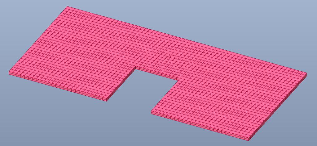
19 Slab with holes 19