OCTARIG SUSPENDED A CLASSIC. WIDE SPANS. WITHOUT COMPROMISE.
|
|
|
- Arnold Collins
- 5 years ago
- Views:
Transcription
1 OCTA RIG


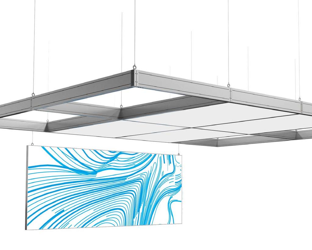
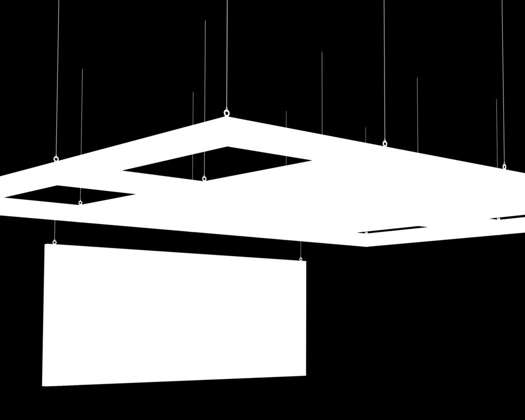
2 OCTARIG SUSPENDED A CLASSIC. WIDE SPANS. WITHOUT COMPROMISE. R 102 DIMENSIONS IN MM: System. 3 Designs. Suspended, elevated or as pylon construction OCTArig gives you the freedom to realize any desired booth concept. The result is a quickly built up and stable construction in compliance with local regulations to hold your equipment. Compatible. Flexible. Adjustable. Invisible cable management, track mounting and countless possibilities to individualize the system make it ideal for the construction of your project. Rotated through 180, the power rails can already be prefitted on the floor. With its high load capacity, OCTArig sets standards in terms of safety both in connection with stage and event technologies and no matter if used with hanging banners or fabric tensioning. ANGLE ADJUSTMENT WITH R 350 AND M 770: Technical Details: wide span of up to 12 m high load capacity easy assembly with only a few parts invisible cable management individual design possibilities compatible with stage and event technologies connection at variable angles with hinged elements power rail mounting 2

3 TECHNISCHE TECHNICAL FEATURES OCTArig suspended 3


4 OCTARIG ELEVATED STABILITY. HIGH LOAD CAPACITY. MOUNTED ON UPRIGHTS. R 102 TURNED 180 : No suspension points on site? No problem. A venue's ceiling construction does not always allow for a suspension of the OCTArig system. Elevated, the system opens up completely new possibilities: up to 6 m ceiling height even without any suspension points. OCTArig stable on uprights. The new R 210 connector is firmly screwed to the upright. OCTArig cannot only be suspended from the ceiling but is also firm and stable on uprights. The reinforcement R 240 provides additional stability and higher load capacity. The construction can be premounted on the floor and elevated to the corresponding height using lifting gear. ROUND TUBE MOUNTED WITH R 362: R 240 DIMENSIONS IN MM:

5 TECHNICAL FEATURES OCTArig elevated REINFORCED CONNECTION. FOR HIGHER LOAD CAPACITY. 5


6 OCTARIG AS PYLON ROOFED. SELF-SUPPORTING. THE PYLON DESIGN. ADDITIONAL BEAM RETAINER R 320: Pylon outstanding 3 m. The pylon design allows for the construction of self-supporting corners of up to 3 m, held only by clamping elements without the need for additional ceiling suspension. A solid ceiling construction, independent of suspension points or supporting ceiling elements on-site just the way you want it. Fewer uprights. More exhibition space. Maximum floor space with a system featuring a simple design that easily fits into every stand architecture. Wherever you decide to place the uprights, OCTArig gives you the freedom you need for your presentation area. PYLON CONSTRUCTION: R 102 IN CONNECTION WITH TENSION BRACE JUNCTION KNOT 6

7 TECHNICAL FEATURES OCTArig Pylon SELF-SUPPORTING CORNERS. MORE FLOOR SPACE. MORE IMPACT. 7
8 8
9 9


 0.47 kg 241 mm 240.6 80.")


10 SUPPORTING BEAM MM R Aluminium for adaptor R 260 and connector R 290, for installation of 4 tension lock Z 961/ kg 6930 mm R 200 R 260 R 102 COVER EXTRUSION FOR R 102 R Aluminium for use with supporting beam R kg 6930 mm R 122 R 102 END PLATE FOR R 102 R Steel for use with supporting beam R 102, incl. 4 set screw M 1075/20 (M4) 0.47 kg 241 mm R 102 R 135 SQUARE EXTRUSION AS UPRIGHT DFS Aluminium for upright, upright extension and upright pylon extension kg 5040 mm R 210 R 102 Processing Notes see page Ø6.7 DFS 84 R 240 BASE PLATE FOR DFS 84 DFL Steel with 6 drill hole for countersunk screws M8, for centre, edge or corner set-up, incl. 4 screw M8 25 DFL 180/ kg 200 DFL 180 DFS


11 COMPONENTS OCTArig CONNECTOR FOR R 260 R Aluminium/Steel to mount adaptor R 260 in case of suspension, incl. eyelet, with 16 x thread M kg Ø35 M R 260 R 200 R 102 R 102 Attention: max. load capacity 500 kg CONNECTOR FOR R 260/DFS 84 R Aluminium/Steel to mount adaptor R 260 for elevation of the construction, plug on and screw to uprights made of DFS 84, incl. 16 thread M kg M R 210 DFS 84 R 102 R CONNECTOR FOR PYLON CONSTRUCTION R Aluminium/Steel for pylon construction with tension brace junction knot R 408, to screw on adaptor R 260, incl. 16 thread M kg M R 400 R ANGLE REINFORCEMENT FOR R 260/DFS 84 R Steel for reinforcement of elevated OCTArig designs, twopiece, incl. 4 contersunk screw DFL 340/5S(M8), 2 contersunk screw R 240/20 (M8), 2 contersunk screw R 240/21 (M8) 6.25 kg R 210 DFS 84 R 102 R 240 Attention: R 260 required for assembly of upright DFS 84 with R 210 and R 102. ADAPTOR FOR DFS 84/R 102 R Aluminium to mount to upright extrusion DFS 84 and supporting beam R 102, incl. 4 cylinder screw R 260/21 (M10) and 6 contersunk screw DFL 340/5S (M10) 1.15 kg l 140 mm R 260 R 200 R 102 R 102 Attention: R 260 required for mounting of supporting beam R 102 between two upright extrusions DFS


12 Attention: R 290 required for mounting of extended supporting beam between two upright extrusions DFS 84. CONNECTOR STRAIGHT R Aluminium for connection of 2 supporting beam R 102, incl. 12 countersunk screw DFL 340/5S (M10) 2.30 kg l 450 mm R 102 R 290 FIXING SET WITH EYELET R Steel to turn into supporting beam R 102, for rope suspension 1.06 kg 127 Ø35 R 300 Attention: max. load capacity 300 kg R 102 TENSION BRACE JUNCTION KNOT FOR R 200 R Steel for modification of connector R 200, incl. cylinder screw R (M16)0.32 kg R 408 R Ø68 TENSION BRACE JUNCTION KNOT FOR DFS 84 R Steel to mount to upright pylon extension DFS 84, incl. 4 cylinder screw R (M8) 2.25 kg R 420 M8 R 102 Attention: necessary for safety reasons. BEAM RETAINER FOR R 102 R Steel for additional securing of 2 supporting beam R 102 at an angle of 90, incl. 2 hammerhead screw M 810/HA (M10) and 2 hammerhead screw E 265 (M10) 0.46 kg R 320 R

 and 4 hammerhead screw E")


13 COMPONENTS OCTArig BEAM RETAINER FOR R 102 R Steel for additional securing of 3 supporting beam R 102 at an angle of 90, incl. 2 hammerhead screw M 810/ HA (M10) and 4 hammerhead screw E 265 (M10) 0.90 kg R 102 R 322 Attention: necessary for safety reasons. BEAM RETAINER FOR M 770 R Steel for additional securing of supporting beam M 770 to supporting beam R 102 at an angle of 90, incl. 4 hammerhead screw M 810/HA (M10) 0.43 kg R 102 R 330 M 770 Attention: necessary for safety reasons. HINGED END PLATE SET FOR M 770 R Steel for connection of supporting beam M 770 to supporting beam R 102 at variable angles, consisting of 2 hinged flange plate M 1557 and 1 wing nut set R 350/FS kg R 102 R 350 M 770 Attention: max. load capacity 100 kg SUPPORTING BEAM MM M Aluminium possible installation of 2 tension lock Z 961/ kg 6930 mm R 330 M R 102 END CAP R Plastic to cover drill holes with Ø 24 mm 0.01 kg 1.6 Ø Ø29.2 R 102 R


14 END CAP R Plastic to cover drill holes with Ø 13 mm 0.01 kg R 102 Ø17 R 358 FIXING-SET FOR R 365 R Attention: max. load capacity 100 kg Steel/Aluminium to slide into the 4.3 mm system groove from the side, incl. 1 hammerhead screw E 265 and mount for round tube Ø 50 mm 0.64 kg Ø R 102 R 365 R 362 ROUND EXTRUSION Ø 50 MM R Aluminium Ø 50 mm 5.06 kg 6000 mm 50 R R 365 R 362 FIXING CLIP FOR POWER RAILS R Aluminium for mounting power rails to 4.3 mm system groove, with clamping screw M4 and fixing accessories M5 (SW 8 mm) 0.02 kg ~ R R 370 ADAPTOR FOR ROPE SUSPENSION M Attention: max. load capacity 150 kg Steel usable for rope suspension, for connection to 4.3 mm system groove, incl. 3 set screw M 1435/70 (M8) and 2 lenticular flange head screw M 1557/20 (M6) 0.53 kg Ø M


 and 2")
 0.25 kg 76 33.5 15.")

15 COMPONENTS OCTArig ADAPTOR FOR ROPE SUSPENSION M Steel usable for rope Ø22 suspension, for connection to 4.3 mm system groove, incl. 2 set screw M 1435/70 (M8) and 2 lenticular flange head screw M 1557/20 (M6) 0.25 kg M 1174 Attention: max. load capacity 100 kg R 102 FABRIC MOUNTING M 1325 M 1330 M 1310 M 1310 M 1358 M 1360 M
16 16

17 17
18 Cross-section values for upright extrusion DFS 84 and rectangular extrusion R 102 LEGEND EXTRUSION OUTER DIMENSION CENTROIDAL AXIS A cross-section h b e y e z G weight mm mm mm mm J moment of inertia DFS W moment of resistance R o o 40.0 i radius of gyration u u 40.0 b ez ez b ez ez h DFS 84 R 102 y h eyu ey eyo y ey z z EXTRUSION A G J y W y i y J z W z i z e y e z cm 2 kg/m cm 4 cm 3 cm cm 4 cm 3 cm DFS R Material: aluminium EN AW-6060 T66 specific weight: 2,70 g/cm³
19 TECHNICAL INFORMATION OCTArig DSF 84 and R 102 Load capacity data for rectangular extrusion R 102 The given data is valid under the condition that the extrusions are structurally prevented from twisting. Sufficient evidence for both flexural buckling and torsional flexural buckling has to be provided. Values printed in blue indicate reaching of the tension limit with a safety factor of Load figures include the dead weight of the extrusion, i.e. the indicated load can be used in whole for addtional extrusions or exhibits. Flexible mounting was estimated for calculation so as to demonstrate load bearing capacity and deflection of the R 102 extrusion. In combination with the R 260 adaptor, the R 200 (or DFS 84) connector and the R 102 supporting beam feature a maximum moment of 5.5 knm. The true deformation can be a little bit more than stated in the table below as any slippage between the components cannot be taken into account. R 102 BEAM SPAN Single load in centre of beam (kg) Evenly distributed load (kg/m) Deflection 1/200 (cm) <1.00 <1.25 <1.50 <1.75 <2.0 (<)2.25 Single load in centre of beam (kg) Evenly distributed load (kg/m) Deflection 1/300 (cm) <0.67 <0.83 (<) R 102 BEAM SPAN Single load in centre of beam (kg) Evenly distributed load (kg/m) Deflection 1/200 (cm) (<) Single load in centre of beam (kg) Evenly distributed load (kg/m) Deflection 1/300 (cm) Maximum admissible load (in addition to dead load) and resulting calculated deflections of single span beams at permitted maximum deflection of 1/200 or 1/300 of span. 19
20 Load-bearing capacity Beam extension examples with connector R 290 The following examples show how the possible load capacity increases in equally long constructions with hinged single span beams the closer the extension is in the edge area. PLEASE NOTE: Static calculation of the construction might be necessary in particular cases! R mm 8000 mm 4000 mm BEAM SPAN M = 8 M (CENTRAL EXTENSION) Single load in centre of beam (kg) 174 Single load in centre of beam (kg) 174 Evenly distributed load (kg/m) 43 Evenly distributed load (kg/m) 43 Deflection 1/200 (cm) vorh (P)* vorh (L)** Deflection 1/300 (cm) vorh (P)* vorh (L)** R 290 R mm 6000 mm 8000 mm 1000 mm BEAM SPAN M = 8 M (ECCENTRIC EXTENSION) Single load in centre of beam (kg) 410 Single load in centre of beam (kg) 260 Evenly distributed load (kg/m) 82 Evenly distributed load (kg/m) 52 Deflection 1/200 (cm) 4.00 Deflection 1/300 (cm) *P = point load, **L = line load
21 TECHNICAL INFORMATION OCTArig Load-bearing capacity 8,000 mm R mm 2000 mm 8000 mm BEAM SPAN M = 8 M (ECCENTRIC EXTENSION) Single load in centre of beam (kg) 360 Single load in centre of beam (kg) 262 Evenly distributed load (kg/m) 60 Evenly distributed load (kg/m) 52 Deflection 1/200 (cm) vorh (P)* vorh (L)** Deflection 1/300 (cm) 2.67 R mm 1000 mm 8000 mm BEAM SPAN M = 8 M (ECCENTRIC EXTENSION) Single load in centre of beam (kg) 410 Single load in centre of beam (kg) 260 Evenly distributed load (kg/m) 82 Evenly distributed load (kg/m) 52 Deflection 1/200 (cm) 4.00 Deflection 1/300 (cm)
22 R 290 R mm 6000 mm 9000 mm 1500 mm BEAM SPAN M = 9 M (ECCENTRIC EXTENSION) Single load in centre of beam (kg) 314 Single load in centre of beam (kg) 195 Evenly distributed load (kg/m) 55 Evenly distributed load (kg/m) 35 Deflection 1/200 (cm) 4.50 Deflection 1/300 (cm) 3.00 R mm 9000 mm 3000 mm BEAM SPAN M = 9 M (ECCENTRIC EXTENSION) Single load in centre of beam (kg) 225 Single load in centre of beam (kg) 195 Evenly distributed load (kg/m) 37 Evenly distributed load (kg/m) 34 Deflection 1/200 (cm) vorh (P)* vorh (L)** Deflection 1/300 (cm) *P = point load, **L = line load
23 TECHNICAL INFORMATION OCTArig Load-bearing capacity 9,000 mm R 290 R mm 7000 mm 9000 mm 1000 mm BEAM SPAN M = 9 M (ECCENTRIC EXTENSION) Single load in centre of beam (kg) 314 Single load in centre of beam (kg) 195 Evenly distributed load (kg/m) 55 Evenly distributed load (kg/m) 35 Deflection 1/200 (cm) 4.50 Deflection 1/300 (cm) 3.00 R mm 2000 mm 9000 mm BEAM SPAN M = 9 M (ECCENTRIC EXTENSION) Single load in centre of beam (kg) 314 Single load in centre of beam (kg) 195 Evenly distributed load (kg/m) 50 Evenly distributed load (kg/m) 35 Deflection 1/200 (cm) 4.50 (P)* vorh (L)** Deflection 1/300 (cm)
24 R 290 R mm 6000 mm mm 2000 mm BEAM SPAN M = 10 M (ECCENTRIC EXTENSION) Single load in centre of beam (kg) 241 Single load in centre of beam (kg) 145 Evenly distributed load (kg/m) 38 Evenly distributed load (kg/m) 23 Deflection 1/200 (cm) 5.00 Deflection 1/300 (cm) 3.33 R mm mm 4000 mm BEAM SPAN M = 10 M (ECCENTRIC EXTENSION) Single load in centre of beam (kg) 157 Single load in centre of beam (kg) 145 Evenly distributed load (kg/m) 25 Evenly distributed load (kg/m) 23 Deflection 1/200 (cm) vorh (P)* vorh (L)** Deflection 1/300 (cm) *P = point load, **L = line load
25 TECHNICAL INFORMATION OCTArig Load-bearing capacity 10,000 mm R 290 R mm 7000 mm 1500 mm mm BEAM SPAN M = 10 M (ECCENTRIC EXTENSION) Single load in centre of beam (kg) 241 Single load in centre of beam (kg) 145 Evenly distributed load (kg/m) 38 Evenly distributed load (kg/m) 23 Deflection 1/200 (cm) 5.00 Deflection 1/300 (cm) 3.33 R mm 3000 mm mm BEAM SPAN M = 10 M (ECCENTRIC EXTENSION) Single load in centre of beam (kg) 219 Single load in centre of beam (kg) 145 Evenly distributed load (kg/m) 31 Evenly distributed load (kg/m) 23 Deflection 1/200 (cm) vorh (P)* vorh (L)** Deflection 1/300 (cm)
26 R 290 R mm 6000 mm mm 2500 mm BEAM SPAN M = 11 M (ECCENTRIC EXTENSION) Single load in centre of beam (kg) 187 Single load in centre of beam (kg) 108 Evenly distributed load (kg/m) 27 Evenly distributed load (kg/m) 15 Deflection 1/200 (cm) 5.50 Deflection 1/300 (cm) 3.67 R mm mm 5000 mm BEAM SPAN M = 11 M (ECCENTRIC EXTENSION) Single load in centre of beam (kg) 118 Single load in centre of beam (kg) 108 Evenly distributed load (kg/m) 19 Evenly distributed load (kg/m) 15 Deflection 1/200 (cm) vorh (P)* vorh (L)** Deflection 1/300 (cm) *P = point load, **L = line load
27 TECHNICAL INFORMATION OCTArig Load-bearing capacity 11,000 mm R 290 R mm 7000 mm 2000 mm mm BEAM SPAN M = 11 M (ECCENTRIC EXTENSION) Single load in centre of beam (kg) 187 Single load in centre of beam (kg) 108 Evenly distributed load (kg/m) 27 Evenly distributed load (kg/m) 15 Deflection 1/200 (cm) 5.50 Deflection 1/300 (cm) 3.67 R mm 4000 mm mm BEAM SPAN M = 11 M (ECCENTRIC EXTENSION) Single load in centre of beam (kg) 150 Single load in centre of beam (kg) 108 Evenly distributed load (kg/m) 21 Evenly distributed load (kg/m) 15 Deflection 1/200 (cm) vorh (P)* vorh (L)** Deflection 1/300 (cm)
28 R mm mm 6000 mm BEAM SPAN M = 12 M (CENTRAL EXTENSION) Single load in centre of beam (kg) 90 Single load in centre of beam (kg) 77 Evenly distributed load (kg/m) 15 Evenly distributed load (kg/m) 10 Deflection 1/200 (cm) vorh (P)* vorh (L)** Deflection 1/300 (cm) 4.00 R 290 R mm 6000 mm mm 3000 mm BEAM SPAN M = 12 M (ECCENTRIC EXTENSION) Single load in centre of beam (kg) 145 Single load in centre of beam (kg) 77 Evenly distributed load (kg/m) 19 Evenly distributed load (kg/m) 10 Deflection 1/200 (cm) 6.00 Deflection 1/300 (cm) *P = point load, **L = line load
29 TECHNICAL INFORMATION OCTArig Load-bearing capacity 12,000 mm R 290 R mm 7000 mm 2500 mm mm BEAM SPAN M = 12 M (ECCENTRIC EXTENSION) Single load in centre of beam (kg) 145 Single load in centre of beam (kg) 77 Evenly distributed load (kg/m) 19 Evenly distributed load (kg/m) 10 Deflection 1/200 (cm) 6.00 Deflection 1/300 (cm) 4.00 R mm 5000 mm mm BEAM SPAN M = 12 M (ECCENTRIC EXTENSION) Single load in centre of beam (kg) 110 Single load in centre of beam (kg) 77 Evenly distributed load (kg/m) 16 Evenly distributed load (kg/m) 10 Deflection 1/200 (cm) vorh (P)* vorh (L)** Deflection 1/300 (cm)
30 Connector & Supporting Beam Type V for OCTArig suspended TECHNICAL INFORMATION OCTArig suspended connector R 200 adaptor R 260 supporting beam R 102 with B 142 TIR-A90.0D E A-T00 A Freigegeben ED 30
31 Connector & Supporting Beam Type V for OCTArig suspended TECHNICAL INFORMATION OCTArig suspended A ( 1 : 10 ) A 240 TIR-A99.0D E A-T99 A Freigegeben ED 31
32 120,3 Upright & Supporting Beam Type A for OCTArig elevated TECHNICAL INFORMATION OCTArig elevated upright DFS 84 with B ,5 adaptor R 260 supporting beam R 102 with B 142 (if required, additional hole for upright extension/connecting piece!) up to 3m max. recommended. TIR-A00.0D E A-T00 A Freigegeben ED 32
33 120,3 120,3 Upright/Upright Extension & Supporting Beam Type A for OCTArig elevated TECHNICAL INFORMATION OCTArig elevated upright DFS 84 with B 148 adaptor R 260 upright extension DFS 84 with B ,5 10,5 T-supporting beam R 102 with B 142 (if required, additional hole for upright extension/connecting piece.) (if required, additional hole for upright extension/connecting piece.) up to 3m max. recommended. TIR-A01.0D E A-T01 A Freigegeben ED 33
34 Upright & Supporting Beam Type A for OCTArig elevated TECHNICAL INFORMATION OCTArig elevated A (1 : 10) A 3000 max TIR-A09.0D E A-T09 A Freigegeben ED 34
35 120,3 Upright & Supporting Beam Type B for OCTArig elevated TECHNICAL INFORMATION OCTArig elevated connector R 210 upright DFS 84 with B ,5 adaptor R 260 upright R 102 with B 142 angle reinforcement R 240 (if required, additional hole for upright extension/connecting piece.) TIR-A10.0D E A-T10 A Freigegeben ED 35
36 120,3 120,3 Upright/Upright Extension & Supporting Beam Type B for OCTArig elevated TECHNICAL INFORMATION OCTArig elevated connector R 210 adaptor R 260 upright R 102 with B 142 upright DFS 84 with B 148 upright extrusion DFS 84 with B ,5 10,5 angle reinforcement R 240 (if required, additional hole for upright extension/connecting piece.) (if required, additional hole for upright extension/connecting piece.) TIR-A11.0D E A-T11 A Freigegeben ED 36
37 Upright & Supporting Beam Type B for OCTArig elevated TECHNICAL INFORMATION OCTArig elevated A (1 : 10) R 210 A upright DFS 84 with B max R 240 TIR-A19.0D E C-T19 A Freigegeben ED 37
38 120,3 Upright & Supporting Beam Type C for OCTArig elevated TECHNICAL INFORMATION OCTArig Pylon tension brace junction knot R 420 upright pylon extension DFS 84 with B 146 upright DFS 84 with B ,5 round tube with clamping element M 1460 with B 145 adaptor R 260 upright R 102 with B 142 adaptor R 260 connector 80 mm R 400 angle reinforcement R 240 (if required, additional hole for upright extension/connecting piece.) TIR-A20.0D E A-T20 A Freigegeben ED 38
39 120,3 120,3 Upright/Upright extension & Supporting Beam Type C for OCTArig elevated TECHNICAL INFORMATION OCTArig Pylon tension brace junction knot R 420 upright pylon extension DFS 84 with B 146 round tube with clamping element M 1460 with B 145 adaptor R 260 upright DFS 84 with B 148 upright extension DFS 84 with B ,5 supporting beamr 102 with B 142 adaptor R 260 connector 80 mm R 400 angle reinforcement R 240 (if required, additional hole for upright extension/connecting piece.) TIR-A21.0D E A-T21 A Freigegeben ED 10,5 (if required, additional hole for upright extension/connecting piece.) 39
40 Upright & Supporting Beam Type C for OCTArig elevated TECHNICAL INFORMATION OCTArig Pylon B B (1 : 10) R 420 C A 3000 max 6000 max min. about. 30 R 400 or R R 408 C ( 1 : 15 ) upright DFS 84 upright pylon extrusion DFS 84 R 240 A (1 : 10) TIR-A29.0D E E-T29 A Freigegeben ED max
41 TECHNICAL INFORMATION OCTArig Processing Notes PROCESSING NOTES B 142 Processing of rectangular beam extrusion R 102 for use with adaptor connector R 260 and internal connector straight R stepped hole 30.6 length B 147 Processing of rectangular beam extrusion R 102 for use with rectangular beam extrusion R length 2 stepped hole 8 drilling Ø 13 mm 70.6 Ø13 Ø B 146 Processing of upright pylon extension DFS 84 for use with adaptor connector R 260 and angle reinforcement R 240 M 10 (16x) thread M10, 4 drilling Ø 10.5 mm, 8 thread M8 (front) 28 Länge B 148 Processing of upright extrusion DFS 84 for use with adaptor connector R 260 and angle reinforcement R thread M10, 4 drilling Ø 10.5 mm, thread M8 (front) length Ø10.5 (4x) M10 (16x) Ø10.5 (4x) if required, additional hole for upright extension 120 If required 4 additional holes Ø 10.5 mm (Please specifiy when ordering.) B 149 Processing of upright extrusion DFS 84 for use with upright extrusion DFS 84 as connector 4 drilling Ø 10.5 mm 120 length Ø10.5 (4x) Ø10.5 (4x) if required, additional hole for upright extension If required 4 additional holes Ø 10.5 mm and/ or 4 threads M8 (Please specifiy when ordering.) 41
42 EXHIBITION SYSTEMS PROJECT SOLUTIONS PRESENTATION INTERIOR DESIGN CLEANROOM SYSTEMS
43
44 OCTANORM Germany Head Office Raiffeisenstraße Filderstadt T F EUROPE OCTANORM Belgium T OCTANORM France T OCTANORM UK T OCTANORM Hellas T AMERICA OCTANORM North America T OCTANORM México T OCTANORM Brasil T OCTANORM Argentina T OCTANORM Italia T OCTANORM Nederland T OCTANORM Polska T OCTANORM Adria T OCTANORM Espana T AFRICA OCTANORM South Africa T MIDDLE EAST OCTANORM Emirates T AUSTRALIA OCTANORM Australia T ASIA AW 7948.GB_OCTARIG_06/2018 OCTANORM Nordic T OCTANORM Russia T OCTANORM Japan T OCTANORM China T