Prepared by Elie F. Issa, Eng. D.E.C. August 2016
|
|
|
- Beverly Prosper Shepherd
- 5 years ago
- Views:
Transcription

1 Prepared by Elie F. Issa, Eng. D.E.C. August 2016

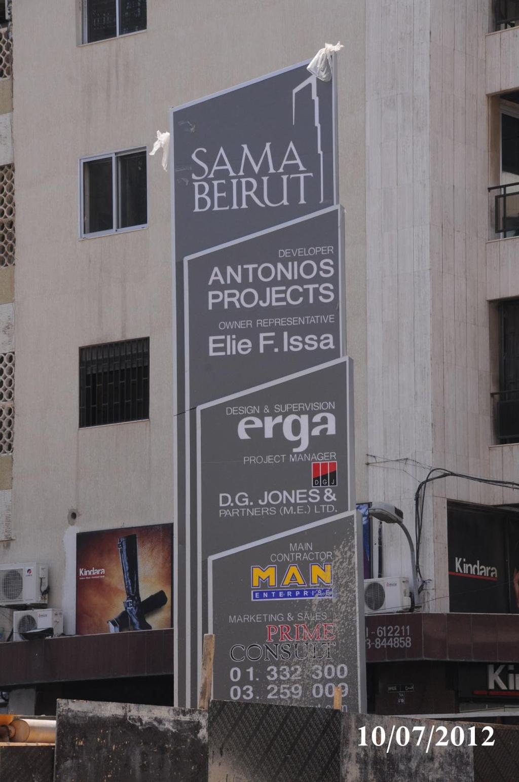
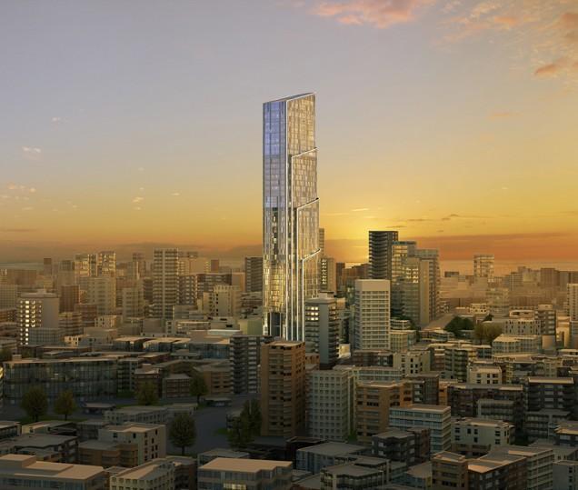
2 SAMA BEIRUT Sama Beirut is the tallest reinforced concrete tower in Lebanon soaring at a height of 220m from ground level
3
4 Project Entities Owner Antonios Projects Owner Representative Eng. Elie F. Issa Marketing & Sales Prime Consult Project Manager D.G.Jones & Partners (ME) Lead Consultant Erga Main Contractor MAN Enterprise And many sub consultants & subcontractors
5 A word about real estate market in Lebanon The market demand nowadays leans towards small apartments and loft style apartments which is the new trend. Vertical longitudinal buildings better fit these requirements than the low rise buildings Going vertical does not use large spaces of land and comprises more offices and residential spaces. Going vertical leaves ground floor spaces for greenery and public areas. Going vertical releases the views giving 360 degrees panoramic exposure of properly designed.
6 A word about Sama Beirut Sama Beirut offers retail space, offices & residential units Flexibility in sizes & types of residential units and offices. Areas ranging from 290 m2 for simplexes to 500 m2 duplexes A penthouse of 1,400 m2 as a villa in the sky & amenities 6 Basements offering 720 parkings despite Beirut congestion State of the art Home Automation systems for the next decade Centrally located in the capital which is a key factor in real estate 5,000 m2 of land & 1,000 m2 tower footprint, rest is landscaped LEED environmental design first of its nature in Lebanon Optimized utilities cost thanks to energy saving LEED design BMU especially customized for continuous cleaning of facade.
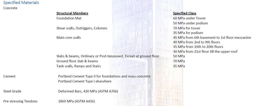
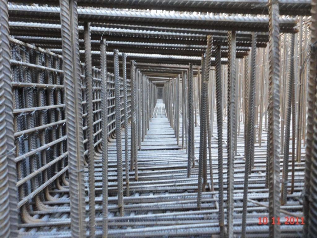
7 Structural Elements Key Features Quantity of Concrete in Foundation 8,200 m3 Quantity of Concrete in Structure 40,000 m3 Quantity of Reinforcing Steel in Foundation 1,500 T Quantity of Reinforcing Steel in Structure 10,000 T (Excluding the Post Tensioned PT Slabs)
8 Steel Reinforcement Specifications Especially imported for Sama Beirut with high ductility This steel type was not available in the local market Reinforcing Bars: ASTM A 615/A 615M, Grade 60 (Grade 420 MPa), deformed Low-Alloy-Steel Reinforcing Bars: ASTM A 706/A 706M, deformed
9 Concrete Mix Design Specifications The highest concrete mix design is (70 Mpa) Actual compressive strength exceeds 80 Mpa Cement content 450 kg / m3 Water / cement ratio w/c = from 0.3 to 0.4 Renowned laboratory for testing ACTS Third Party Control office BVL

10
11 The design in accordance with UBC 1997 code considering a zone factor of Z=0.25g This is equivalent to 7.5 on the Richter Scale As per the requirements of the Lebanese Public safety Law, decree #7964 (issued in and applicable since ). Additional seismic construction detailing were considered to increase the ductility of the reinforced concrete primary members. Outriggers also connecting core walls CW1 & CW2 Closure strip connecting the core wall and the slabs

12 "Bearing wall system with reinforced concrete shear walls" is the adopted main lateral load resisting system Central core-wall connected to the outer frame s wing walls with reinforced concrete outriggers located at the different technical floors

13
 was retained by Erga to study the structural wind loading The wind tunnel data were analytically analyzed with the structural properties of the tower The objectives of")
 The above allowed for a revised structural report and")
14 Rowan Williams Davies & Irwin Inc. (RWDI) was retained by Erga to study the structural wind loading The wind tunnel data were analytically analyzed with the structural properties of the tower The objectives of this study were: - To provide wind loading information for the overall structural design - To determine the wind-induced accelerations at the uppermost occupied floors The wind tunnel test shows the wind load to be prevailing over the seismic load on the façade (on the lateral facades of the tower) The above allowed for a revised structural report and cladding report The results showed low wind speeds of 1.5 kpa (150 kg/m2) at the low zones and high speeds of 3.25 kpa (325 kg/m2) at the high zones.
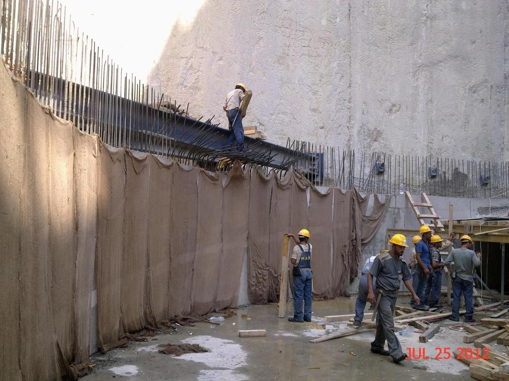
15 The façade was subjected to several testing at 3 rd party laboratory testing with M/S Exova in Dubai. Tests were the following: Static air pressure water penetration Dynamic air pressure water penetration Wind resistance serviceability test Wind resistance safety was 150% from actual pressure To note that according to the most stringent scenario, the windows and façade systems.


16

17
18
19
20

21

22 Soil profile type marl rock soil is used in line with the project s geotechnical report findings Foundation was designed as deep foundation with piles 26 meters deep Then it became matt foundation under the tower with strip footings to counter the uplift from the swelling effect of the soil When swelling was not an issue, the foundation design became a raft over the area

23 SOIL PROFILE The soil profile is constituted of a top soil, overlaying a soft Beige Marl and followed be a Grey Compact Marl considered as quasi impervious.
24 D-Wall Shoring works D-Wall serves as permanent wall & tanking system to the structure. 4 levels of anchors over more than 20m deep Special water treatment done later to prevent leakage

25

26 SHORING Seven basements covering all the surface of the plot (~ m²) were executed. The shoring is a Permanent Diaphragm Wall of 62 cm thick, it was maintained during the working phases with anchors and struts and directly supported with the basement slabs during the final service phase.

27 FOUNDATION The Diaphragm Wall acts also as a deep foundation, while the tower itself was founded on a general raft of 3m thick, covering about m² only.
28 TH= CL TH= TH=800 TH=1600 TH= TH= TH=800 TH=1600 TH=2400 TH= TH=800 TH=1400 TH= CL TH=1000 TH=2600 TH= CL CL TH=1000 TH=800 TH=1400 TH=2000 TH= TH= CL TH=1800 TH= CL TH=1600 TH=800 TH=800 TH=1400 TH=2000 TH=2600 TH= TH=2400 TH=1600 TH=800 TH=2000 TH= TH= TH=2000 TH=1400 TH=800 TH= CL TH=1300 TH= CL CL TH= CL TH= TH= CL CL TH= CL TH= CL TH= CL TH=600 WATER INFLOW Considering a Water Head of 21m, the inflow of water entering the excavation should not exceed : Q 10 m³/h for the whole site. TH=800 TH=800 TH=800 TH=800 TH=1400 TH=1400 TH=1400 TH=1400 TH=2000 TH=2000 TH=2000 TH=2000 TH=2600 TH=2600 TH=2600 TH=2600 TH=800 TH= CL CL TH=800 With such a limited value, a permanent pumping network was implemented, eliminating thus the uplift pressure and the need for tension piles. TH=800 TH=2000 TH=800 TH=2000 TH=2000 TH= CL TH=2000 Ech : 1/150 TH=2000 TH=800
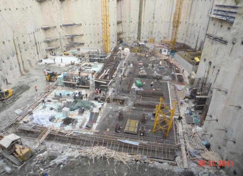
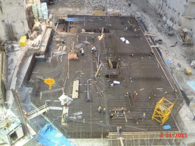
29 During Construction of Foundation Sama Beirut Raft foundation is huge in terms of both depth and surface area The area of the raft stretches over 5,000 m2 Depths ranges between 3.2m to 4.5m deep in the elevators pits.
30
31
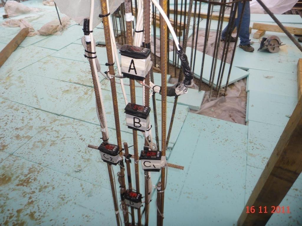
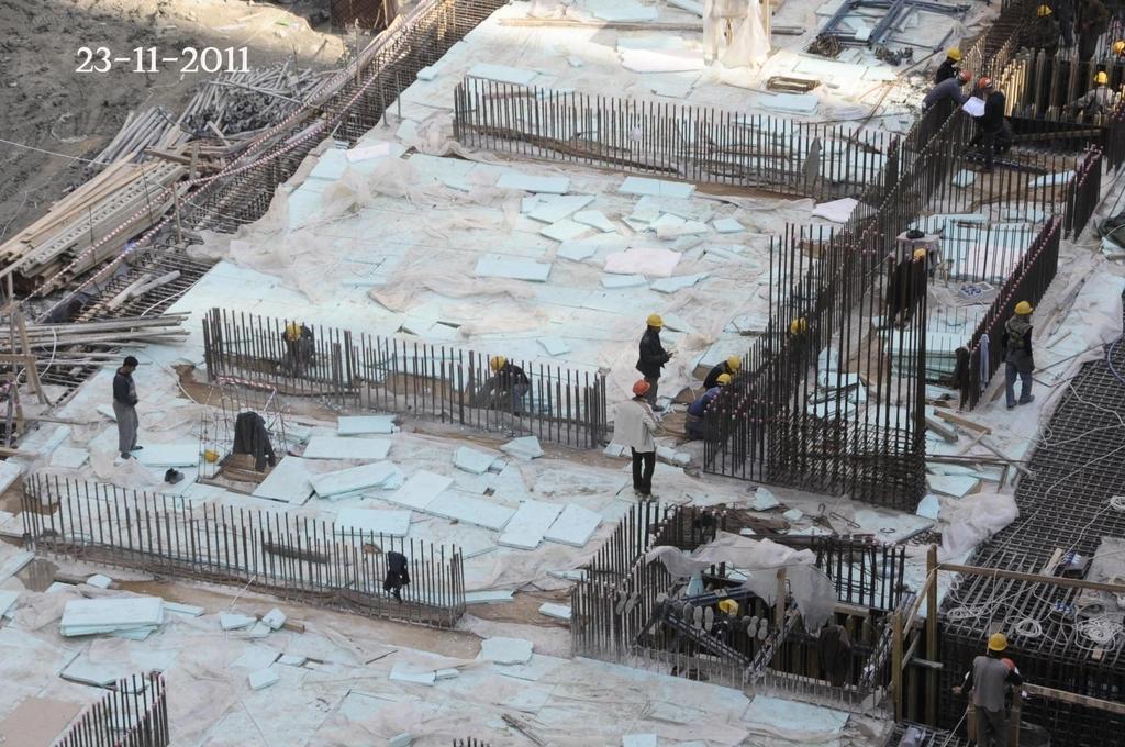
32 During Construction of Foundation Temperature control, due to hydration process was achieved by: The use of thermo-couplers on three 3 levels, low, mid and upper. The use of Styrofoam on the top of the Raft Curing to control the effects of hydration Continuous readings to monitor temperture

33

34

35
36 During Construction of Foundation Pouring sequence done in 4 separate zones to prevent cold joints The distribution of the concrete very well studied due to the huge area of the raft Special arrangement with the municipality done to guarantee continuous pouring (24 hrs)

37

38
39 During Construction of Foundation All aggregates from a single source Make sure there is uniformity Same chemical & physical properties in mix Testing done many times & before pouring Make sure quality control is assured
40 Settlement Monitoring Devices Required to install a system for measurement of the Tower Raft settlement and load transfer through the main structural members to the raft. The system monitors the raft lateral movement and inclination along with load cells under the major structural load bearing mega columns.
41 BTS BC 5 SETTLEMENT STRIP BC 1 SETLLEMENT STRIP BC 3 BC 2 BC 4 BC 6 SETLLEMENT STRIP TOWER FOOTPRINT BC 7 LOW RISE AREAS

42 MODEL: GEOKON A3 MPBX DATE INST: Oct M DEEP HOLES FOUR ANCHORS PER HOLE
43 Settlement strip pouring procedure Settlement monitoring devices installed to measure the settlement of the building Sensors installed at 5 different locations at different depths Settlement is measured during construction & a minimum of three 3 years after construction Several structural elements are poured late when the structure has settled enough These include the settlement strip between the tower and podium, outrigger walls etc


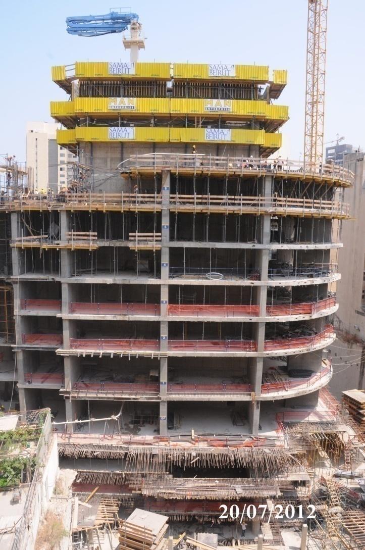
44


45
46 Settlement strip pouring procedure The late pouring elements were cast when the structure was complete The readings of the settlement monitoring devices indicated a settlement of 1.3 cm Compensation in the settlement was taken into account in the upper floors vertical elements The overall projected settlement of the structure is about 2.2 cm validated by actual readings


47


48
49 Concrete Mix Design The increase of the strength of the concrete mix design was achieved not by the addition of cement but rather the control of the water to cement ratio which is much better. To note that the ACI does not limit the cement content in the mix design which in SB is 450kg/m3
50 Testing for Creep & Shrinkage The testing for creep and shrinkage was done by an internationally renowned and certified laboratory based in the United Kingdom over a period of 12 months. As such, and based on the results received, the structural design was updated and other late pouring elements were poured mainly the closure strip between the core walls and slabs on each floor.
51 Post Tension Slabs Area of post tension 40,000 m2 Compressive strength f c = 50 MPA Ultra thin post tension slabs of 22 cm Big Span lengths Number of columns minimized


52
53 Core Wall Construction Method ACS used (Automatic Climbing System) Operated by hydraulic Jacks & placing boom on top Optimizes pouring cycle time & minimizes labor force Has three levels, pouring, formwork & concrete repair Core wall always is ahead of slabs by 3 floors


54
55