structural design of mass timber framing systems
|
|
|
- Noah Gibson
- 5 years ago
- Views:
Transcription


1 structural design of mass timber framing systems northeast wood design symposium tanya luthi, p.e. fast +epp september26, 2018 Disclaimer: This presentation was developed by a third party and is not funded by WoodWorksor the Softwood Lumber Board
2 Copyright Materials This presentation is protected by US and International Copyright laws. Reproduction, distribution, display and use of the presentation without written permission of the speaker is prohibited. Fast + Epp 2018
3 The Wood Products Council is a Registered Provider with The American Institute of Architects Continuing Education Systems (AIA/CES), Provider #G516. Credit(s) earned on completion of this course will be reported to AIA CES for AIA members. Certificates of Completion for both AIA members and non-aia members are available upon request. This course is registered with AIA CES for continuing professional education. As such, it does not include content that may be deemed or construed to be an approval or endorsement by the AIA of any material of construction or any method or manner of handling, using, distributing, or dealing in any material or product.
4 course description Mass timber structural framing systems have high strength-to-weight ratios, are dimensionally stable, and are quickly becoming systems of choice for sustainably minded designers. This presentation will provide a detailed look at the structural design processes associated with a variety of mass timber products, including glued-laminated timber (glulam), cross-laminated timber (CLT), and naillaminated timber (NLT). Applications for the use of these products in gravity force-resisting systems under modern building codes will be discussed. Other technical topics will include use of mass timber panels as two-way spanning slabs, connection options and design considerations, and detailing and construction best practices.
5 Attheendofthiscourse,participantswillbeableto: 1. Discuss mass timber products and building systems and their possibilities as structural framing. 2. Compare structural properties and performance characteristics of mass timber products and review their unique design considerations. 3. Review structural design steps for members and connections in common mass timber framing systems. 4. Highlight structural detailing best practices to address items such as shrinkage and expansion, load path continuity, and speed of construction. learning objectives
6 1 gravity framing 2 lateral systems 3 connections overview


")
7 gravity framing nail-laminated timber (NLT) structural composite lumber (LSL, LVL) cross-laminated timber (CLT) glulam panels (GLT) wood-concrete composites decks plank decking
 choose: depth,")

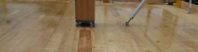
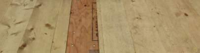
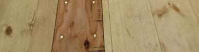
8 gravity framing 2x joists at 38mm (1-1/2 ) choose: depth, profile species, grade continuousvs. butt-jointed laminations NLT design


9 gravity framing detail for shrinkage and swelling NLT design

10 gravity framing design guide thinkwood.com NLT design


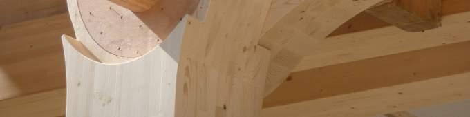
11 gravity framing beam on the flat A A A A A A A A A A A GLT design


12 gravity framing detail for shrinkage and swelling GLT design
13 gravity framing dimensional stability APA PRG 320 defines structural grades panel sizes vary by supplier cross laminations reduce strength and stiffness in primary span direction CLT design


14 gravity framing 2-way span capability CLT design


15 CLT design


16 gravity framing design guide thinkwood.com CLT design
17 gravity framing NLT may be most appropriate if: floor structure spans one way floor structure is curved in one direction budget is tight structure is an addition or alteration to an existing building (no crane access from above) a less manufactured aesthetic is desired decisions decisions...
18 gravity framing GLT may be most appropriate if: floor structure spans one way spans are long (no strength/stiffness reduction as for NLT with butt joints) a clean aesthetic is desired decisions decisions...
19 gravity framing CLT may be most appropriate if: floor structure needs to span in two directions (e.g. weak-axis cantilevers) a clean aesthetic is desired accommodating shrinkage and swelling during construction is difficult tight tolerances are required decisions decisions...
20 gravity framing 2x4 NLT, 3 GLT, 3-ply CLT (4 ±) 12 approx. L/40 2x6 NLT, 5 GLT, 5-ply CLT (7 ±) approx. L/20 to L/40 typical spans
21 gravity framing 2x8 NLT, 7 GLT approx. L/24 to L/36 2x10 NLT, 8 1/2 GLT, 7-ply CLT (10 ±) approx. L/22 to L/34 typical spans
22 gravity framing 2x12 NLT, 9-ply CLT (12 ±) approx. L/20 to L/28 typical spans
23 gravity framing deflections include creep ponding effects for concrete toppings? vibrations when in doubt, calculate accelerations! damping values? AISC Design Guide 11 (2 nd Edition) CSA O86 Annex A NBC 2015 Structural Commentary D ISO serviceability
24 1 gravity framing 2 lateral systems 3 connections overview


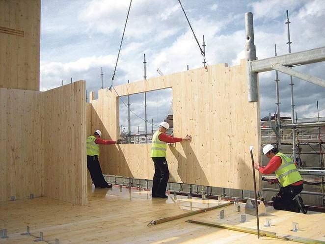
25 lateral systems shear walls Photo Credit: Sissi Slotover-Smutny vertical LFRS


26 lateral systems rocking walls vertical LFRS rocking moment frames Illustration Credit: PresLam


27 Photo Credit: Equilibrium Consulting wood braced frames vertical LFRS hybrids (steel or concrete LFRS)
28 lateral systems wood, steel, or concrete? walls or frames? code approvals building height and lateral load demands designing for resilience? architectural and planning considerations decisions decisions...


29 diaphragms


30 diaphragms lateral systems
31 lateral systems white paper Brenemanet al, An Approach to CLT Diaphragm Modeling for Seismic Design with Application to a U.S. High-Rise Project design example Structurlamet al, CLT Horizontal Diaphragm Design Example CLT diaphragm design aids
32 1 gravity framing 2 lateral systems 3 connections overview


33 the devil is in the details what s your philosophy? connections

34 connections in concrete Photo Credit: Reiulf Ramstad Arkitekter


35 Photo Credit: Cast Connex connections in steel Photo Credit: Ben McMillan
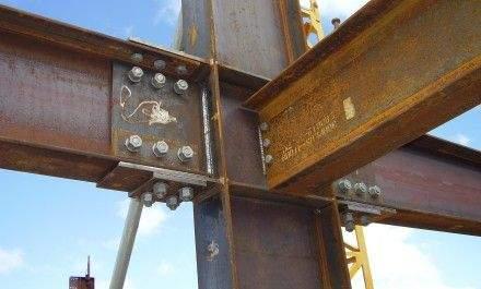


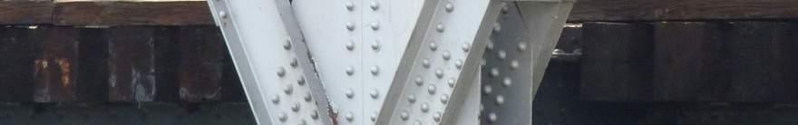

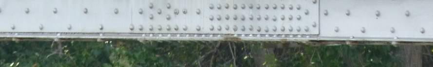
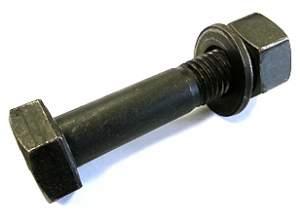
36 connections in steel


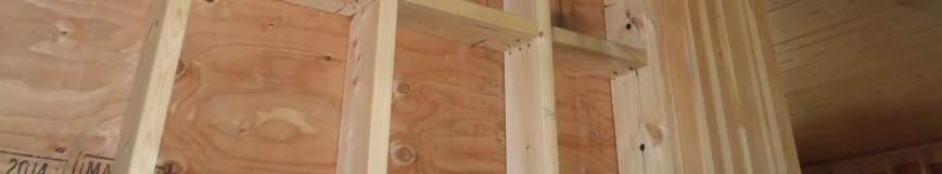
37 Photo Credit: Simpson StrongTie connections in stick frame


38 Photo Credits: Fire Tower Engineered Timber connections in timber frame


39 Photo Credit: TimberPlates.com Photo Credit: VicBeam Photo Credit: Uihlein-Wilson Architects connections timber? in hybrids and mass


40 connections timber? in hybrids and mass Photo Credits: Shigeru Ban Architects
41 connections make it buildable make it beautiful and don t forget about mother nature what s philosophy? your


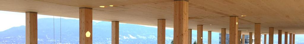
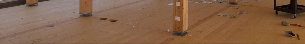
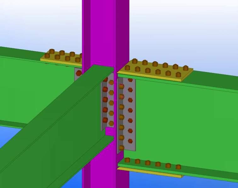
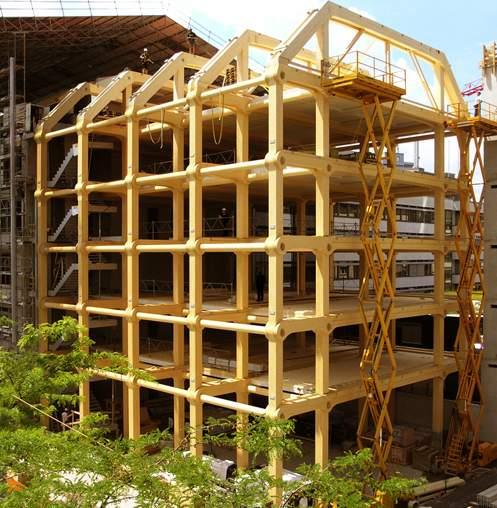
42 column connection tallwoodhouse at brock commons

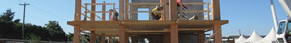

43 column connection tallwoodhouse at brock commons


44 column connection Photo Credit: Seagate Structures


45 column connection tallwoodhouse at brock commons
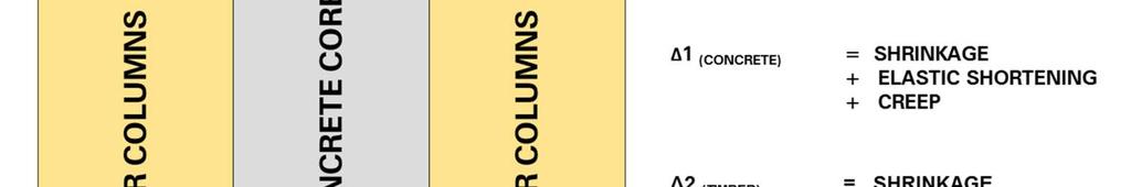
46 2 tallwoodhouse at brock commons 1.5 Deflection (in) Dead Load Elastic Live Load Elastic Longitudinal Shrinkage Creep and Joint Settlement Total column connection
47 column connection tallwoodhouse at brock commons
48 column connection tallwoodhouse at brock commons


49 column connection


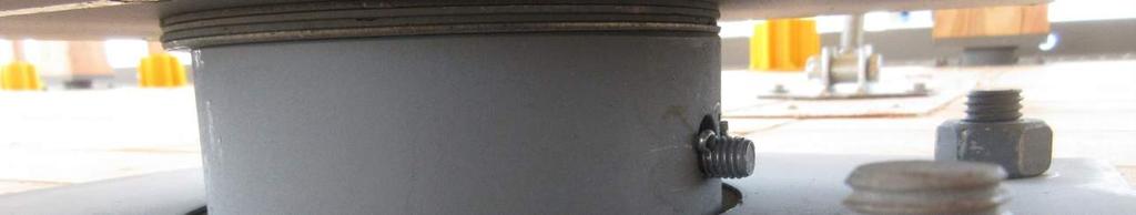
50 mec head office a a Photo Credit: DGS Construction a -a beam saddle
51 mec head office Photo Credit: DGS Construction beam saddle


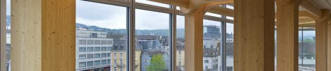
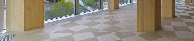
52 wilsonschool of design a a Photo Credit: DGS Construction tight-fit pin shear connection a - a
53 tight-fit pin shear connection wilsonschool of design


54 tight-fit pin shear connection wilsonschool of design
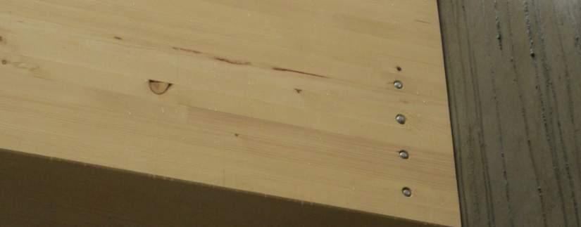
55 ubc bus shelters Photo Credit: PUBLIC self-tapping screws


56 ubc bus shelters Photo Credit: SFS Intec self-tapping screws

57 self-tapping screws ubc bus shelters
58 self-tapping screws ubc bus shelters


59 HSK plate moment connection whistler gateway loop
60 HSK plate moment connection whistler gateway loop

61 whistler gateway loop Photo Credit: TiComTec HSK plate moment connection


62 HSK plate moment connection whistler gateway loop


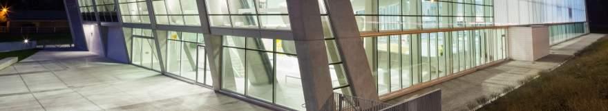


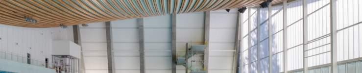
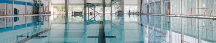

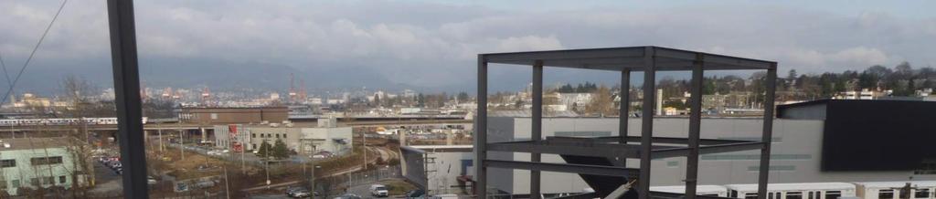
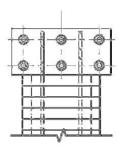
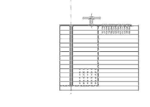
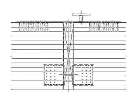
63 grandviewheights aquatic centre Photo Credits: Ema Peter tension splice

64 grandviewheights aquatic centre PLAN VIEW tension splice

65 tension splice grandviewheights aquatic centre

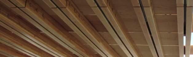
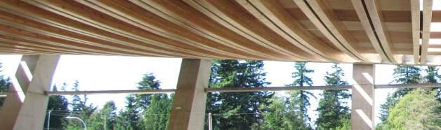

66 tension splice grandviewheights aquatic centre

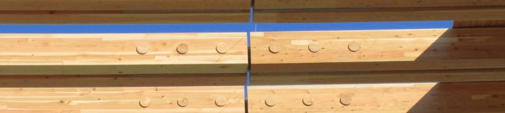
67 tension splice grandviewheights aquatic centre

68 arena stage performing arts center Photo Credit: Nic Lehoux steel casting


69 arena stage performing arts center Photo Credit: Nic Lehoux steel casting


70 arena stage performing arts center Image Credits: StructureCraft Builders steel casting

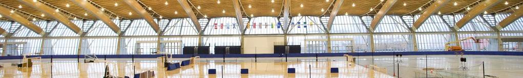

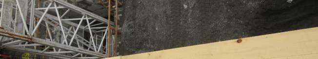
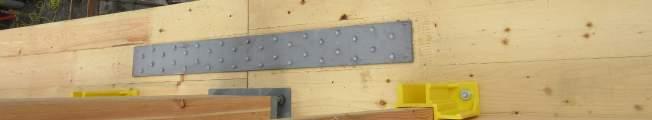
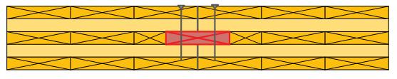
71 shrinkage crack reinforcement richmond olympicoval
72 a richmond olympicoval a a -a shrinkage crack reinforcement


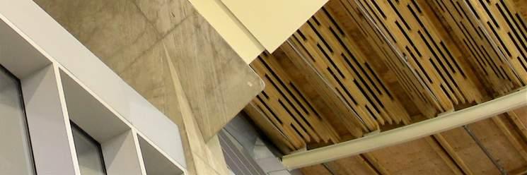
73 shrinkage crack reinforcement richmond olympicoval
74 first principles it s not rocket science, but you re not just a structural engineer anymore in closing


75 This concludes the American Institute of Architects Continuing Education Systems Course thank you Contact Us: 11th Floor, 41 East 11th St. New York, NY Tel: