Roof Edge Fabrications Guardrails
|
|
|
- Reginald Miller
- 5 years ago
- Views:
Transcription

1 O&M - KEEGUARD
2


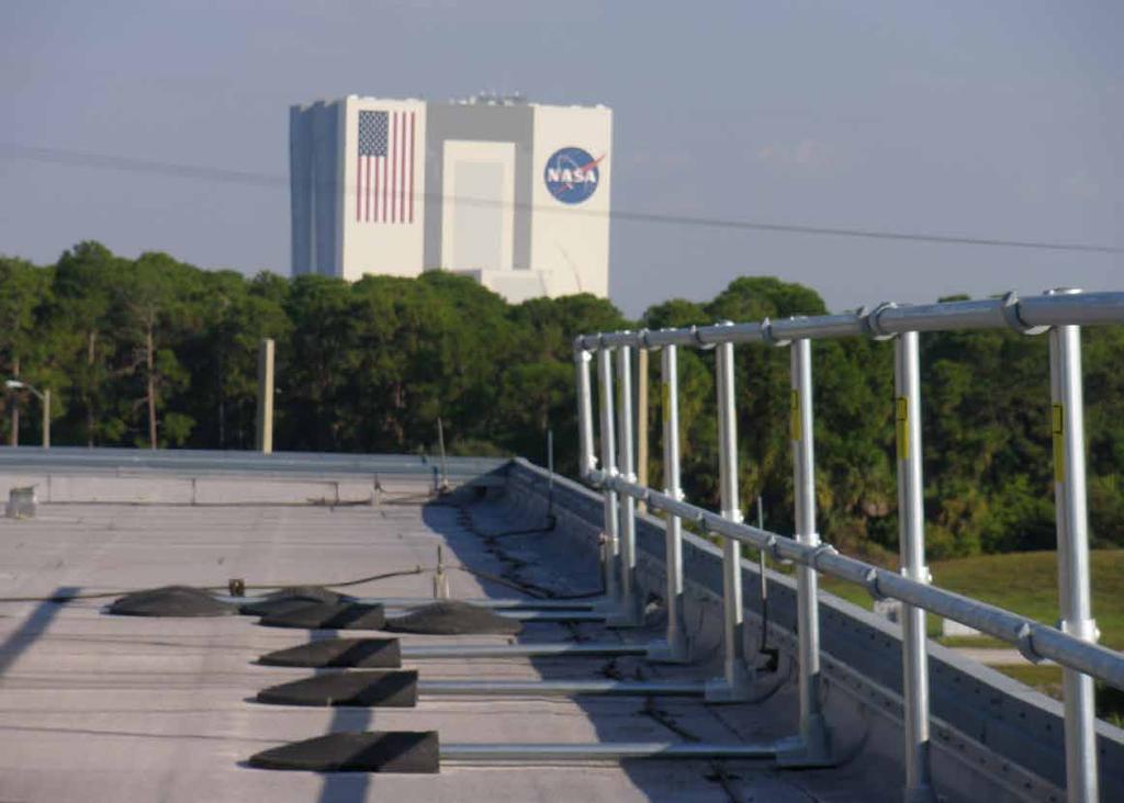
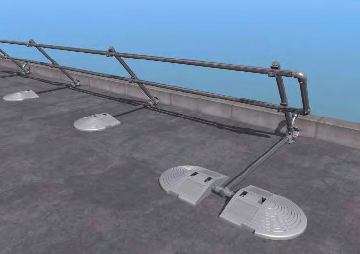
3 Roof Edge Fabrications Guardrails ROOF EDGE FABRICATIONS GUARDRAILS Roof Edge Fabrications guardrail systems including System 2000 and KeeGuard have been designed specifically to provide permanent edge protection for areas where regular access for maintenance and inspection is required. UNIQUE SYSTEMS Each system s unique design provides permanent edge protection without the need to mechanically fix the system through the roofing membrane or building s structure. Their simple cantilever principle provides unrivalled strength, stability and safety and overcomes the problems associated with traditional systems such as having to drill and puncture the roof membrane which can lead to potential penetrative water damage and noise disturbance during installation. Similarly, high levels of insulation included within warm deck and inverted flat roof designs often mean it is virtually impossible to fix through, as with traditional systems, without causing cold bridging. This may then cause interstitial condensation to form within the flat roof construction, causing the roof to deteriorate and eventually require replacement. DURABLE SYSTEMS Roof Edge Fabrications guardrail components are supplied with a galvanised finish carried out to BS EN ISO 1461: Hot Dip Galvanised Coatings Specification and Testing Methods, giving an average coating of between microns. All products are also available in aluminium. All locking screws are stainless steel and are greased before fixing to ensure a maintenance free system. COMPONENT BASED SYSTEMS All systems consist of galvanised tubing joined together using the Kee Klamp method of connection. System 2000 features a vertical leg that has been specifically designed so that the base foot can be raised or lowered allowing the system to be levelled during installation. In addition to this, the sliding base foot allows future re-roofing works to be completed without the need to dismantle the system. KeeGuard, raked, radiused and folding systems base feet connect to the 100% recycled PVC counter weight, giving the system its strength & stability. VERSATILE SYSTEMS All systems have been specially designed to fit any shape and size of flat and pitched roofs, even circular designs. The systems can also cope with changes in levels, roof falls and difficult details such as ductwork passing over the roof edge and cable trays/plant mounted at the roof edge. The flexibility of the counter weight & Kee Klamp design allows the systems to be used on plant congested or complex detailed roofs. The product range has been extended to suit specific requirements and includes the standard design with vertical legs, raked and radiused systems, as well as a folding version for areas where a more discreet form of protection is required. MEMBRANE PROTECTION SYSTEMS Each system is installed with fluted rubber matting bonded to the underside of metal components which come into contact with the roof membrane. In some cases the counter weight and base foot have sacrificial pads placed between the edge protection components and the roof membrane.
4 Roof Edge Fabrications Guardrails This protects the roof membrane from damage via heat transfer or direct contact with components. On warm deck roof construction specifications pedestrian tiles are recommended to be placed where base feet and counter weights are in contact with the roof membrane. TESTING & CERTIFICATION Tested in accordance with EN Class A. WIND CALCULATED BS 6399 : Part 2 Code of Practice for Wind Load. Wind loading is the most likely regular and demanding force a free standing roof guardrail will encounter during its lifetime. Roof Edge Fabrications has developed a computerised programme to calculate the design to ensure compliance with the relevant wind loadings relating to the topography, height and location of the project throughout the UK. OFFICIAL DOCUMENTATION All Systems comply with the following:- Work at Height Regulations EN 13374: Temporary Edge Protection Systems Product Specification Test Methods BS 6399 : Part 2 Code of Practice for Wind Load. HSG 33 Health & Safety in Roof work HSE Construction Sheet No. 21 Working on flat roofs protection against falls. European Union Directives together with requirements of CDM Regulations. AESTHETICS The smooth lines of the standard galvanised finish can be further enhanced by the application of powder coating to BS 6497 Specification for Powder Organic Coatings, with bespoke colour produced to special order. Counter weights are available in black or other colours at an additional cost. Where a more discreet form of protection is required, raked and radiused systems, as well as a folding version are welcomed by Planning Officers due to their improved aesthetics. SYSTEMS DISTRIBUTORS All systems are available as a supply and installation service or component supply only. Products are available from Roof Edge Fabrications directly or one of its licensed distributors within the UK. INDUSTRIAL CLADDED ROOFS Roof Edge Fabrications has developed a new collective roof edge protection system specifically for metal profile and standing seam roofs up to 45. Pitched cladded roofs have traditionally been protected using personal fall protection systems which are lower in the hierarchy of control ranking.

. The vertical support legs are produced in steel - 48.3mm external diameter. (Wall thickness 3.2mm) Cantilever tubes are produced in steel 42.")
5 KeeGuard Edge Protection System PRODUCT SPECIFICATION FEATURES :- Standard Vertical, Raked, Radiused System Recycled PVC Counter Weight System GENERAL KeeGuard systems do not require physical fixing into the roof s structure/membrane. The complete system s design, manufacture, testing and installation has been externally assessed and tested to EN MATERIALS The products are fabricated from steel to BS EN S275 Grade and S275JO Grade. All steel components are then hot dipped galvanised to BS EN ISO Guardrail top and intermediate rails are produced in steel mm external diameter. (Wall thickness 3.2mm). The vertical support legs are produced in steel mm external diameter. (Wall thickness 3.2mm) Cantilever tubes are produced in steel 42.4mm external diameter. (Wall thickness 3.2mm) All fixing screws are A2 Grade Stainless Steel and are greased before installation. All cast clamps used to join the guardrail are galvanised malleable cast iron produced to BS EN 1562 : founding malleable cast iron. All metal components in contact with the roof membrane are covered with 3mm fluted rubber. Counter weights are manufactured from recycled PVC. Where tubing is cut on site zinc rich paint is applied to the cut end of the tube. LAYOUT Height of guardrail is set at 1100mm. All vertical supports are set at maximum 3m centres depending on the system. Recycled PVC counter weights are attached to every vertical leg set at no more than 3m centres. At corner Support Legs there is no need for a PVC Counter Weight to be connected. All stop ends are triple counter weighted or supported by way of a wall/ladder clamp. TESTING All systems have been tested to EN 13374: Temporary Edge Protection Systems - Product Specification Test Methods and have been awarded a Class A Pass. WIND LOADING All installations are wind speed calculated to BS 6399 : Part 2 : Code of Practice for Wind Loads.
6 Complies with EN Class A - Edge Protection System FIGURE 1 Free Standing End Detail Intermediate Counter Weight Intermediate Counter Weight


7 KeeGuard Edge Protection System 103mm 53mm Size 8 130mm Size 7 55mm 140mm 75mm *BASE FOOT This unique component provides support to the system and allows the system to be set at 90º or raked back at 11º. The Base Foot connects the Cantilever Tubes and Counter Weights. The base is bonded with fluted rubber matting for membrane protection. Material : Malleable cast iron to BS 1562 and galvanised to BS EN ISO Net weight : 2kg. *SADDLE CLAMP This open cup fitting provides the method of linking the horizontal Main Rail Tubes to the Support Legs. Material : Malleable cast iron to BS 1562 and galvanised to BS EN ISO Net weight : 0.77kg. 90mm 60mm 68mm 68mm 90º-180º 90º ELBOW This provides the means of dealing with corners and changes in level. Material : Malleable cast iron to BS 1562 and galvanised to BS EN ISO Net weight : 0.76kg. ADJUSTABLE SIDE OUTLET TEE ELBOW Used in pairs these components deal with angles 90º-180ºand changes in level. Material : Malleable cast iron to BS 1562 and galvanised to BS EN ISO Net weight : 1kg. 136mm 104mm 68mm THREE SOCKET TEE CONNECTOR This component can be used in many different instances, for example, changes in level. Material : Malleable cast iron to BS 1562 and galvanised to BS EN ISO Net weight : 1.08kg. STRAIGHT COUPLING This component provides the method to link the horizontal Main Rail Tubes. Material : Malleable cast iron to BS 1562 and galvanised to BS EN ISO Net weight : 0.6kg. * Sold as replacement parts only
 (1575mm - CBT2) This component provides the link between the Counter Weight and Base Foot. Material : Galvanised steel to BS EN ISO 1461.")

8 Complies with EN Class A - Edge Protection System O/D 42.4mm 1075mm 1575mm CANTILEVER TUBE - (1075mm - CBT1) (1575mm - CBT2) This component provides the link between the Counter Weight and Base Foot. Material : Galvanised steel to BS EN ISO Cantilever tubes are produced in steel 42.4mm external diameter. (Wall thickness 3.2mm) First/last Cantilever tube length 1575mm Net weight : 4.48kg Intermediate cantilever tube length 1075mm Net weight : 3.26kg O/D 42.4mm 1100mm STANDARD & RAKED SUPPORT LEG - KGU32 This component allows for standard 90º installation or raked back at 11º and provides some height adjustment to the system. The vertical support legs are produced in steel mm external diameter (Wall thickness 3.2mm). Material : Galvanised steel to BS EN ISO Net weight : 7kg. 260mm SMALL CANTILEVER TUBE/COUNTER WEIGHT LINK - CBT3 Used in pairs at the end details these components provide the link between the Counter Weights and the Cantilever Tube via the Two Socket Cross fitting. Material : Galvanised steel to BS EN ISO Tubes are produced in steel 42.4mm external diameter. (Wall thickness 3.2mm) Net weight : 0.78kg mm 400mm R 3100 MAIN RAIL TUBE (6.4M )(3.2M HL)(2.133m ) Supplied in three sizes for convenience, these components provide the horizontal rails of the system. Guardrail top and intermediate rails are produced in steel mm external diameter (Wall thickness 3.2mm). Material : Galvanised steel to BS EN ISO Net weight : 22.9kg, 11.45kg. & 7.6kg. RADIUSED SUPPORT LEG - KGUR This is designed to allow the system to be radiused and gentle curved back towards the roof slope. This component provides some height adjustment to the system. The vertical Support Legs are produced in steel mm external diameter (Wall thickness 3.2mm). Material : Galvanised steel to BS EN ISO Net weight : 7.8kg.
9 KeeGuard Edge Protection System 85mm 100mm 125mm 460mm 500mm 75mm *RECYCLED PVC COUNTER WEIGHT This component provides the stability to the system. Material : Recycled PVC Net weight : 13.3kg. WALL/LADDER CLAMP - SL109C This component provides the means to terminate the system against a façade or clamp the system to a cat ladder/structure where the stringer is a maximum of 70mm wide. Material : Galvanised steel to BS EN ISO Net weight : 1.1kg. 65mm 75mm COLLAR This component is inserted in the first slot of the recycled PVC Counter Weight. The cantilever tube is pushed through this fitting and the grub screw is then tightened. This component provides the connection between the Cantilever Tube and the Counter Weight. Material : Malleable cast iron to BS 1562 and galvanised to BS EN ISO Net weight : 0.24kg. WALL FIXING - SL110 The wall fixing is used in pairs in conjunction with a Wall Clamp Material : Stainless steel. Net weight : 0.064kg. Variable 700mm 120mm TWO SOCKET CROSS This component is used where two recycled PVC Counter Weights need to be joined together to form a counter weight end detail. Material : Malleable cast iron to BS 1562 and galvanised to BS EN ISO Net weight : 0.63kg. SELF CLOSING GATE - GT25P This component is used to provide a sprung loaded access point. Material : Galvanised steel to BS EN ISO Net weight : 16.3kg.


10 Complies with EN Class A - Edge Protection System 50mm PLASTIC CAP - SL105 This component is fitted to the top of the Support Leg to prevent water ingress. Material : PVC. Net weight : 0.009kg.

11 KeeGuard Assembly Guide STANDARD & RAKED SUPPORT LEG (KGU32) OR RADIUSED SUPPORT LEG (KGUR32) These are supplied already assembled at the correct height (1100mm) with the Base Foot & saddle Clamps set at the correct position. LAYING OUT SUPPORT LEG AND MAIN RAIL TUBES Lay out the equipment in approximately the positions shown below. Always ensure that you and the equipment are at a safe distance from the roof edge. It is a recommendation of Roof-Edge Fabrications that this distance is no less than 2m. Lay out two 6.4m Main Rail Tubes (8610) or (3.2m or 2.13m) side by side and in a continual line, for the whole length of the required guardrail (ensure these do not roll towards the roof edge). Then start laying out the Support leg Units. If your start position is from a corner, start laying out the support legs at a maximum of 3m centres. Carry on laying out the Support Legs for the required length of guardrail. KGU32 KGUR
 2No. Cantilever Tube (CBT2) 4No. Small Cantilever Tube Link (CBT3) 2No. Two Socket Cross (26-7) 6No. Collars (74-7) B FREE STANDING END Extra components 2No.")
12 KeeGuard Assembly Guide Fixed, Free Standing and Intermediate Details A SELF CLOSING GATE ACCESS POINT Extra components 1No. Self Closing Gate (GT25P) 4No. 90 Elbows (15-8) 2No. End pieces 6No. PVC Counter Weights (440-7) 2No. Cantilever Tube (CBT2) 4No. Small Cantilever Tube Link (CBT3) 2No. Two Socket Cross (26-7) 6No. Collars (74-7) B FREE STANDING END Extra components 2No. 90 Elbows (15-8) 1No. End piece 3No. PVC Counter Weights (440-7) 1No. Cantilever Tube (CBT2) 2No. Small cantilever Tube Link (CBT3) 1No. Two Socket Cross (26-7) 3No. Collars (74-7) C WALL CLAMP Extra components 1No. End piece 1No. Three Socket Tee Connector (25-8) 1No. Wall/Ladder Clamp (SL109C) 2No. 90º Elbows (15-8) 2No. Wall Fixings (SL110) LAYING OUT COUNTER WEIGHTS AND CANTILEVER TUBES At any free standing end detail Support Leg, place 1No. Cantilever Tube (CBT2), 1No. Two Socket Cross Clamp (27-7), 2No. Small Cantilever Tubes (CBT3), 3No. PVC Counter Weights (440-7) and 3No. Collars (74-7) At the intermediate Support Legs (max 3m centres) place 1No. Cantilever Tube (CBT1), 1No. PVC Counter Weight (440-7), and 1No. Collar (74-7). At corner Support Legs there is no need for a PVC Counter Weight to be connected (See Figure1.). LAYING OUT FITTINGS Where the 2No. Main Rail Tubes butt together lay out 2No. Straight Couplings (14-8) in order for the Main Rail Tubes to be joined. At corners 2No. 90º Elbows will be used (15-8). (Use Adjustable Side Outlet Tee Elbows in pairs where corners are 90º º (19-8)). See also Fixed, Free Standing and Intermediate Details above for additional required components. (See Figure1.)
13 KeeGuard Assembly Guide STAGE 1 Starting at least 2m away from the roof edge at the corner, stand up the two Support Legs. STAGE 3 Form a corner via connecting 2No 90º Elbows (15-8) to one end of each of the Main Rail Tubes (8610). Position a further Support Leg 3m max from the corner. Slide a Main Rail Tube (8610) into the bottom Saddle Clamp (135-8) and 90º Elbow (15-8). Slide a Main Rail Tube (8610) into the top Saddle Clamp (135-8) and 90º Elbow (15-8). Tighten the grub screws of all clamps. STAGE 2 Place a Main Rail Tube (8610) into the bottom Saddle Clamp (135-8) of each of the standing legs. Position the tube so there is at least 60mm protruding from the Saddle Clamp (135-8) and tighten the Grub Screw. These are located on the front of the Saddle Clamp (135-8). Place the second Main Rail Tube (8610) into the top Saddle Clamp (135-8), positioning the tube as before, leaving at least 60mm of the tube protruding from the Saddle Clamp (135-8) and tighten the Grub Screw of the Saddle Clamp (135-8). STAGE 4 Working in pairs carefully lift the assembled bay and walk towards the leading edge. Carefully place the bay in the desired position and slide the corresponding Counter Weight tube into the Base Foot. (CBT1 (Intermediate Support Leg or CBT2 (Free Standing End Detail). Always ensure the bay is being held in position whist carrying out this part of the assembly. At corner Support Legs there is no need for a PVC Counter Weight to be connected.
14 KeeGuard Assembly Guide STAGE 5 Intermediate support Legs/PVC Counter Weights Slide 1No. Cantilever Tube (CBT1) into the Base Foot. Do not tighten at this stage. Place 1No. Collar (74-7) in the front slot of the PVC Counter Weight. Slide 1No. PVC Counter Weight on to the free end of the Cantilever Tube (CBT1). Line and level guardrail. Tighten all grub screws. STAGE 7 Free Standing End Details Slide 1No. Two Socket Cross (26-7) on to the free end of the Cantilever Tube (CBT2). Do not tighten at this stage. Slide 2No. Small Cantilever Tubes into the free ends of the Two Socket Cross (26-7) and tighten the grub screws holding these tubes into position. Place 1No. Collar (74-7) in the front slot of each PVC Counter Weight. Slide 1No. PVC Counter Weight on to the free end of the Cantilever Tube (CBT2). Slide 1No. PVC Counter Weight on to each of the free ends of the Small Cantilever Tube (CBT3). Position all PVC Counter Weights as far from the Base Foot ( ) as practically possible. Line and level guardrail. Tighten all grub screws. (See Fixed, Free Standing and intermediate Details). STAGE 6 Working away from the corner slide a Straight Coupling (14-8) on to the top and intermediate Main Rail Tubes. Position the clamp so the grub screws are facing outwards and tighten the Grub Screw at the connected end. Stand up the next Support Leg at the desired position (Max 3m centres).continue with this method of fitting the Main Rail Tube (8610) and Support Legs together for this run of guardrail, remembering to connect the intermediate Cantilever Tubes (CBT1) and PVC Counter Weights (440-7) to the Support Legs as you proceed. WARNING Under no circumstances should any person be anchored to the system for fall arrest purposes. Further, components such as timber infill, advertising boards, polyethylene sheets must not be fixed to the system.
15 KeeGuard Assembly Guide
16
17 Guardrail Systems Recertification Periodic inspections by a competent person are required under Regulation 5 of the Workplace (Health, Safety & Welfare) Regulations, the Work at Height Regulations and BS EN 365. The frequency will depend upon the environment, location and usage but should be at least every 12 months. Walk and visually inspect the complete installed system in relation to the general client s needs. Establish if any modifications and/or additional products are required to reflect any refurbishment requirements or additional plant & equipment which have been installed and require access. Check installation configuration is complete as per the original installation drawing/plan. Ensure the system has not been modified or tampered with by unauthorised persons. Check all base feet are in contact with the roof membrane. Check all counter weights are in place as per the original drawing. This is essential for wind loading calculations. Check all grub screws are in place, greased and sufficiently torque. Check that the general height and level of the system including the leg centres. (This only tends to be an issue if the system has been tampered with between inspections). Any galvanised components showing signs of corrosion should be wire brushed thoroughly and galvanised spray/paint applied as appropriate. If rusted significantly, take digital photographs and include these in the inspection report. Where toe-boards are fitted check the brackets that support the toe-board are in place, greased and sufficiently torqued. Where applicable, check fixings to walls/structures including cat ladder clamps are in place, greased and sufficiently torqued. Check system plaque position & mark up to reflect date of the next required inspection. Establish if additional plaques are required due to any refurbishment works.
18 HEAD OFFICE Roof Edge Fabrications Limited t +44 (0) Dalsetter Avenue f +44 (0) Drumchapel e anchors@roofedge.co.uk Glasgow G15 8TE w

19 O&M -KEEGUARD FOLDSHIELD
20
21 Roof Edge Fabrications Guardrails ROOF EDGE FABRICATIONS GUARDRAILS Roof Edge Fabrications guardrail systems including System 2000 and KeeGuard have been designed specifically to provide permanent edge protection for areas where regular access for maintenance and inspection is required. UNIQUE SYSTEMS Each system s unique design provides permanent edge protection without the need to mechanically fix the system through the roofing membrane or building s structure. Their simple cantilever principle provides unrivalled strength, stability and safety and overcomes the problems associated with traditional systems such as having to drill and puncture the roof membrane which can lead to potential penetrative water damage and noise disturbance during installation. Similarly, high levels of insulation included within warm deck and inverted flat roof designs often mean it is virtually impossible to fix through, as with traditional systems, without causing cold bridging. This may then cause interstitial condensation to form within the flat roof construction, causing the roof to deteriorate and eventually require replacement. DURABLE SYSTEMS Roof Edge Fabrications guardrail components are supplied with a galvanised finish carried out to BS EN ISO 1461: Hot Dip Galvanised Coatings Specification and Testing Methods, giving an average coating of between microns. All products are also available in aluminium. All locking screws are stainless steel and are greased before fixing to ensure a maintenance free system. COMPONENT BASED SYSTEMS All systems consist of galvanised tubing joined together using the Kee Klamp method of connection. System 2000 features a vertical leg that has been specifically designed so that the base foot can be raised or lowered allowing the system to be levelled during installation. In addition to this, the sliding base foot allows future re-roofing works to be completed without the need to dismantle the system. KeeGuard, raked, radiused and folding systems base feet connect to the 100% recycled PVC counter weight, giving the system its strength & stability. VERSATILE SYSTEMS All systems have been specially designed to fit any shape and size of flat and pitched roofs, even circular designs. The systems can also cope with changes in levels, roof falls and difficult details such as ductwork passing over the roof edge and cable trays/plant mounted at the roof edge. The flexibility of the counter weight & Kee Klamp design allows the systems to be used on plant congested or complex detailed roofs. The product range has been extended to suit specific requirements and includes the standard design with vertical legs, raked and radiused systems, as well as a folding version for areas where a more discreet form of protection is required. MEMBRANE PROTECTION SYSTEMS Each system is installed with fluted rubber matting bonded to the underside of metal components which come into contact with the roof membrane. In some cases the counter weight and base foot have sacrificial pads placed between the edge protection components and the roof membrane.


22 Roof Edge Fabrications Guardrails This protects the roof membrane from damage via heat transfer or direct contact with components. On warm deck roof construction specifications pedestrian tiles are recommended to be placed where base feet and counter weights are in contact with the roof membrane. TESTING & CERTIFICATION Tested in accordance with EN Class A. WIND CALCULATED BS 6399 : Part 2 Code of Practice for Wind Load. Wind loading is the most likely regular and demanding force a free standing roof guardrail will encounter during its lifetime. Roof Edge Fabrications has developed a computerised programme to calculate the design to ensure compliance with the relevant wind loadings relating to the topography, height and location of the project throughout the UK. OFFICIAL DOCUMENTATION All Systems comply with the following:- Work at Height Regulations EN 13374: Temporary Edge Protection Systems Product Specification Test Methods BS 6399 : Part 2 Code of Practice for Wind Load. HSG 33 Health & Safety in Roof work HSE Construction Sheet No. 21 Working on flat roofs protection against falls. European Union Directives together with requirements of CDM Regulations. AESTHETICS The smooth lines of the standard galvanised finish can be further enhanced by the application of powder coating to BS 6497 Specification for Powder Organic Coatings, with bespoke colour produced to special order. Counter weights are available in black or other colours at an additional cost. Where a more discreet form of protection is required, raked and radiused systems, as well as a folding version are welcomed by Planning Officers due to their improved aesthetics. SYSTEMS DISTRIBUTORS All systems are available as a supply and installation service or component supply only. Products are available from Roof Edge Fabrications directly or one of its licensed distributors within the UK. INDUSTRIAL CLADDED ROOFS Roof Edge Fabrications has developed a new collective roof edge protection system specifically for metal profile and standing seam roofs up to 45. Pitched cladded roofs have traditionally been protected using personal fall protection systems which are lower in the hierarchy of control ranking.

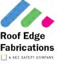
23 KeeGuard Foldshield Edge Protection System PRODUCT SPECIFICATION FEATURES :- Standard Vertical Folding Guardrail System Recycled PVC Counter Weight System GENERAL KeeGuard systems do not require physical fixing into the roof s structure/membrane. The complete system s design, manufacture, testing and installation has been externally assessed and tested to EN MATERIALS The products are fabricated from steel to BS EN S275 Grade and S275JO Grade. All steel components are then hot dipped galvanised to BS EN ISO Guardrail top and intermediate rails are produced in steel mm external diameter. (Wall thickness 3.2mm). The vertical support legs are produced in steel mm external diameter. (Wall thickness 3.2mm) Cantilever tubes are produced in steel 42.4mm external diameter. (Wall thickness 3.2mm) All fixing screws are A2 Grade Stainless Steel and are greased before installation. All cast clamps used to join the guardrail are galvanised malleable cast iron produced to BS EN 1562 : founding malleable cast iron. All metal components in contact with the roof membrane are covered with 3mm fluted rubber. Counter weights are manufactured from recycled PVC. Where tubing is cut on site zinc rich paint is applied to the cut end of the tube. LAYOUT Height of guardrail is set at 1100mm. All vertical supports are set at maximum 3m centres depending on the system. Standard system is formed of 6m bays connected by two cantilevered T sections with connecting tube. Recycled PVC counter weights are attached to every vertical leg set at no more than 3m centres. At corner Support Legs there is no need for a PVC Counter Weight to be connected. All stop ends are triple counter weighted or supported by way of a wall/ladder clamp. TESTING All systems have been tested to EN 13374: Temporary Edge Protection Systems - Product Specification Test Methods and have been awarded a Class A Pass. WIND LOADING All installations are wind speed calculated to BS 6399 : Part 2 : Code of Practice for Wind Loads.
24 Complies with EN Class A - Edge Protection System FIGURE 1 Free Standing End Detail Intermediate Counter Weight Intermediate Counter Weight


25 KeeGuard Foldshield Edge Protection System 130mm Size 8 53mm 110mm Size 7 55mm 175mm 85mm 60mm *HINGED VERSION BASE FOOT A This unique component provides support to the system and allows it to be set vertically at 90º. When the guardrail is not required this Base Foot allows the system to be folded flat on to the roof. The Base Foot connects the Cantilever Tubes and Counter Weights and is bonded with fluted rubber matting for membrane protection. Material : Malleable cast iron to BS 1562 and galvanised to BS EN ISO Net weight : 3.3kg. *SADDLE CLAMP This open cup fitting provides the method of linking the horizontal Main Rail Tubes to the Support Legs. Material : Malleable cast iron to BS 1562 and galvanised to BS EN ISO Net weight : 0.77kg. 90mm 85mm 460mm 500mm 90º-180º *RECYCLED PVC COUNTER WEIGHT This component provides the stability to the system. Material : Recycled PVC Net weight : 13.3kg. ADJUSTABLE SIDE OUTLET TEE ELBOW Used in pairs these components deal with angles 90º-180ºand changes in level. Material : Malleable cast iron to BS 1562 and galvanised to BS EN ISO Net weight : 1kg. 68mm 68mm 104mm 90º ELBOW This provides the means of dealing with corners and changes in level. Material : Malleable cast iron to BS 1562 and galvanised to BS EN ISO Net weight : 0.76kg. STRAIGHT COUPLING This component provides the method to link the horizontal Main Rail Tubes. Material : Malleable cast iron to BS 1562 and galvanised to BS EN ISO Net weight : 0.6kg. * Sold as replacement parts only
26 Complies with EN Class A - Edge Protection System O/D 42.4mm 90º 1075mm 1575mm CANTILEVER TUBE - (1075mm - CBT1) (1575mm - CBT2) This component provides the link between the Counter Weight and Base Foot. Material : Galvanised steel to BS EN ISO Cantilever tubes are produced in steel 42.4mm external diameter. (Wall thickness 3.2mm) First/last Cantilever tube length 1575mm Net weight : 4.48kg Intermediate cantilever tube length 1075mm Net weight : 3.26kg O/D 42.4mm 1100mm STANDARD FOLDING SUPPORT LEG - KFU1 This component allows for standard 90º installation and provides some height adjustment to the system. This component also permits the system to fold. The vertical support legs are produced in steel mm external diameter (Wall thickness 3.2mm). Material : Galvanised steel to BS EN ISO Net weight : 8.3kg. 260mm SMALL CANTILEVER TUBE/COUNTER WEIGHT LINK - CBT3 Used in pairs at the end details these components provide the link between the Counter Weights and the Cantilever Tube via the Two Socket Cross fitting. Material : Galvanised steel to BS EN ISO Tubes are produced in steel 42.4mm external diameter. (Wall thickness 3.2mm) Net weight : 0.78kg. 50mm PLASTIC CAP - SL105 This component is fitted to the top of the Support Leg to prevent water ingress. Material : PVC. Net weight : 0.009kg. 75mm MAIN RAIL TUBE (6.4M )(3.2M HL)(2.133m ) Supplied in three sizes for convenience, these components provide the horizontal rails of the system. Guardrail top and intermediate rails are produced in steel mm external diameter (Wall thickness 3.2mm). Material : Galvanised steel to BS EN ISO Net weight : 22.9kg, 11.45kg. & 7.6kg. WALL FIXING - SL110 The wall fixing is used in pairs in conjunction with a Wall Clamp Material : Stainless steel. Net weight : 0.064kg.


27 KeeGuard Foldshield Edge Protection System 136mm 65mm COLLAR This component is inserted in the first slot of the recycled PVC Counter Weight. The cantilever tube is pushed through this fitting and the grub screw is then tightened. This component provides the connection between the Cantilever Tube and the Counter Weight. Material : Malleable cast iron to BS 1562 and galvanised to BS EN ISO Net weight : 0.24kg. 120mm THREE SOCKET TEE CONNECTOR This component can be used in many different instances, for example, changes in level. Material : Malleable cast iron to BS 1562 and galvanised to BS EN ISO Net weight : 1.08kg. 100mm 125mm 68mm 75mm THREE SOCKET TEE CONNECTOR This component can be used at corners to join Cantilever Tubes together. Material : Malleable cast iron to BS 1562 and galvanised to BS EN ISO Net weight : 0.85kg. 60mm WALL/LADDER CLAMP - SL109C This component provides the means to terminate the system against a façade or clamp the system to a cat ladder/structure where the stringer is a maximum of 70mm wide. Material : Galvanised steel to BS EN ISO Net weight : 1.1kg. Variable 700mm 120mm TWO SOCKET CROSS This component is used where two recycled PVC Counter Weights need to be joined together to form a counter weight end detail. Material : Malleable cast iron to BS 1562 and galvanised to BS EN ISO Net weight : 0.63kg. SELF CLOSING GATE - GT25P This component is used to provide a sprung loaded access point. Material : Galvanised steel to BS EN ISO Net weight : 16.3kg.
28

 or (3.2m or 2.13m) side by side and in a continual line for the bay.")
. Where bays meet (Every 6m) place 2No.")
29 KeeGuard Foldshield Assembly Guide STANDARD SUPPORT LEG (KFU1) These are supplied already assembled at the correct height (1100mm) with the Base Foot & saddle Clamps set at the correct position. LAYING OUT SUPPORT LEG AND MAIN RAIL TUBES Lay out the equipment in approximately the positions shown below. Always ensure that you and the equipment are at a safe distance from the roof edge. It is a recommendation of Roof Edge Fabrications that this distance is no less than 2m. Lay out two 6.4m Main Rail Tubes (8610) or (3.2m or 2.13m) side by side and in a continual line for the bay. Continue for the complete guardrail length required (ensure these do not roll towards the roof edge). Then start laying out the Support leg Units. If your start position is from a corner, start laying out the support legs at a maximum of 3m centres (3No. Support Legs per bay). Where bays meet (Every 6m) place 2No. Support Legs next to one another (see below). Carry on laying out the Support Legs for the required length of guardrail. KFU1
 2No. Cantilever Tube (CBT2) 4No. Small Cantilever Tube Link (CBT3) 2No. Two Socket Cross (26-7) 6No.")
30 KeeGuard Foldshield Assembly Guide Fixed, Free Standing and Intermediate Details A SELF CLOSING GATE ACCESS POINT Extra components 1No. Self Closing Gate (GT25P) 4No. 90 Elbows (15-8) 2No. End pieces 6No. PVC Counter Weights (440-7) 2No. Cantilever Tube (CBT2) 4No. Small Cantilever Tube Link (CBT3) 2No. Two Socket Cross (26-7) 6No. Collars (74-7) B FREE STANDING END Extra components 2No. 90 Elbows (15-8) 1No. End piece 3No. PVC Counter Weights (440-7) 1No. Cantilever Tube (CBT2) 2No. Small cantilever Tube Link (CBT3) 1No. Two Socket Cross (26-7) 3No. Collars (74-7) C WALL CLAMP Extra components 1No. End piece 1No. Three Socket Tee Connector (25-8) 1No. Wall/Ladder Clamp (SL109C) 2No. 90º Elbows (15-8) 2No. Wall Fixings (SL110) 2No. Straight Couplings (!4-8) 2No. 200mm lengths of tube LAYING OUT COUNTER WEIGHTS AND CANTILEVER TUBES At any free standing end detail Support Leg, place 1No. Cantilever Tube (CBT2), 1No. Two Socket Cross Clamp (27-7), 2No. Small Cantilever Tubes (CBT3), 3No. PVC Counter Weights (440-7) and 3No. Collars (74-7) At the intermediate Support Legs (max 3m centres) place1no. Cantilever Tube (CBT1), 1No. PVC Counter Weight (440-7), and 1No. Collar (74-7). Where 6m bays abut place 1No Y-Cantilever Tube (CBTY), 1No. PVC Counter Weight (440-7) and 1No. Collar (74-7). At corner Support Legs place 1No. Cantilever Tube (CBT2), 1No Three Socket Tee Connector (25-7). (See Figure1.) LAYING OUT FITTINGS Where the 2No. Main Rail Tubes butt together lay out 2No. Straight Couplings (14-8) in order for the Main Rail Tubes to be joined. Where the 6m bays butt to one another place 4No. 90º Elbows (15-8) and 2No end pieces. At corners place 2No. 90º Elbows (15-8), 2No. Straight Couplings (14-8) and 2No. 200mm lengths of Main Rail Tubes. (Use Adjustable Side Outlet Tee Elbows in pairs where corners are 90º º (19-8)). See also Fixed, Free Standing and Intermediate Details above for additional required components. (See Figure1.)
31 KeeGuard Foldshield Assembly Guide STAGE 1 Starting at least 2m away from the roof edge at the corner, stand up the two Support Legs. STAGE 3 Form a corner via connecting 2No 90º Elbows (15-8) to one end of each of the Main Rail Tubes (8610). Position a further Support Leg 250mm max from the corner. Connect 1No. 200mm length of Main Rail Tube to each of the 90º Elbows (15-8). Slide 1No. Straight Coupling (14-8) on to each of the 200mm lengths of Main Rail Tubes. Slide a Main Rail Tube (8610) into the bottom Saddle Clamp (135-8) and Straight Coupling (14-8).Slide a Main Rail Tube (8610) into the top Saddle Clamp (135-8) and Straight Coupling (14-8). Tighten the grub screws of all clamps. STAGE 2 Place a Main Rail Tube (8610) into the bottom Saddle Clamp (135-8) of each of the standing legs. Position the tube so there is at least 60mm protruding from the Saddle Clamp (135-8) and tighten the Grub Screw. These are located on the front of the Saddle Clamp (135-8). Place the second Main Rail Tube (8610) into the top Saddle Clamp (135-8), positioning the tube as before, leaving at least 60mm of the tube protruding from the Saddle Clamp (135-8) and tighten the Grub Screw of the Saddle Clamp (135-8). STAGE 4 Working in pairs carefully lift the assembled bay and walk towards the leading edge. Carefully place the bay in the desired position and slide the corresponding Counter Weight tube into the Base Foot/Feet. (CBT1) Intermediate Support Leg or CBT2 (Free Standing End Detail) or (CBTY) where the bays abut one another). Always ensure the bay is being held in position whist carrying out this part of the assembly. At the corner support Leg connect 2No. Cantilever Tubes together using Three Socket Tee Connector (25-7) as shown below. Tighten all grub screws.
32 KeeGuard Foldshield Assembly Guide STAGE 5 Place 1No. Collar (74-7) in the front slot of the PVC Counter Weight. Slide 1No. PVC Counter Weight on to the free end of the Cantilever Tube (CBT1) (CBTY). Line and level guardrail. Tighten all grub screws. STAGE 7 Free Standing End Details Slide 1No. Two Socket Cross (26-7) on to the free end of the Cantilever Tube (CBT2). Do not tighten at this stage. Slide 2No. Small Cantilever Tubes into the free ends of the Two Socket Cross (26-7) and tighten the grub screws holding these tubes into position. Place 1No. Collar (74-7) in the front slot of each PVC Counter Weight. Slide 1No. PVC Counter Weight on to the free end of the Cantilever Tube (CBT2). Slide 1No. PVC Counter Weight on to each of the free ends of the Small Cantilever Tube (CBT3). Position all PVC Counter Weights as far from the Base Foot ( ) as practically possible. Line and level guardrail. Tighten all grub screws. (See Fixed, Free Standing and intermediate Details). STAGE 6 Continue to assemble the components to form each 6m bay. Where bays abut one another connect the top and intermediate Main Rail Tubes together by slide 1No 90º Elbow (15-8) on to each of the 4No. Main Rail Tubes. Insert an end piece between each pair of 90º Elbow (15-8). Line, level and tighten all grub screws. WARNING Under no circumstances should any person be anchored to the system for fall arrest purposes. Further, components such as timber infill, advertising boards, polyethylene sheets must not be fixed to the system.

33 KeeGuard Foldshield Assembly Guide STAGE 8 When desired the system can simply be lowered in 6m bay lengths. Carefully remove the pins from the 2No. end base feet. Then remove the pin of the centre Base Foot and move backwards & lower the guardrail. Note:- Ensure you are using appropriate PPE and anchored to an approved anchorage point before commencing.

34 KeeGuard Foldshield Assembly Guide
35 Guardrail Systems Recertification Periodic inspections by a competent person are required under Regulation 5 of the Workplace (Health, Safety & Welfare) Regulations, the Work at Height Regulations and BS EN 365. The frequency will depend upon the environment, location and usage but should be at least every 12 months. Walk and visually inspect the complete installed system in relation to the general client s needs. Establish if any modifications and/or additional products are required to reflect any refurbishment requirements or additional plant & equipment which have been installed and require access. Check installation configuration is complete as per the original installation drawing/plan. Ensure the system has not been modified or tampered with by unauthorised persons. Check all base feet are in contact with the roof membrane. Check all counter weights are in place as per the original drawing. This is essential for wind loading calculations. Check all grub screws are in place, greased and sufficiently torque. Check that the general height and level of the system including the leg centres. (This only tends to be an issue if the system has been tampered with between inspections). Any galvanised components showing signs of corrosion should be wire brushed thoroughly and galvanised spray/paint applied as appropriate. If rusted significantly, take digital photographs and include these in the inspection report. Where toe-boards are fitted check the brackets that support the toe-board are in place, greased and sufficiently torqued. Where applicable, check fixings to walls/structures including cat ladder clamps are in place, greased and sufficiently torqued. Check system plaque position & mark up to reflect date of the next required inspection. Establish if additional plaques are required due to any refurbishment works.


36 HEAD OFFICE Roof Edge Fabrications Limited t +44 (0) Dalsetter Avenue f +44 (0) Drumchapel e anchors@roofedge.co.uk Glasgow G15 8TE w