TECHNICAL MANUAL. Bolted Column Connection (for Seismic applications) Seismic-proof Application of Bolted Connections
|
|
|
- Lillian Jefferson
- 5 years ago
- Views:
Transcription


1 TECHNICAL MANUAL Bolted Column Connection (for Seismic applications) Seismic-proof Application of Bolted Connections Version: PEIKKO GROUP 09/2016

2 Bolted Column Connection For seismic applications Ductile and energy dissipating precast concrete column connection Advanced casting process with the help of standard accessories Safe and simple assembly procedure of the columns Cost-eff ective construction method with reduced man- and crane-hours Peikko s Bolted Column Connection is a solution for connecting precast concrete columns to cast-in-place foundation elements. This connection is capable of transferring axial forces, shear forces and bending moments from column to foundation under seismic conditions. Peikko s Bolted Column Connection is prequalified, which means that ductile and energy dissipative behavior of it was experimentally verified through numerous quasi-static cyclic tests according to ACI 374.2R-13 following requirements of EN :2004/AC:2009. The system consists of column shoes casted into precast concrete column and anchor bolts casted into foundation. The connection is finalized by filling the joint between column and foundation with high strength non-shrink grout. After the grout has reached the design strength the connection acts as reinforced concrete structure. Shear force transfer is achieved by means of anchor bolts with anti-lock washers and mechanical interlocking between grout and concrete. The main advantage in using bolted connections is that an immediate connection is made. Column can be installed on construction site without temporary bracings only by leveling and tightening the nuts. Epoxy resin is then injected inside shoe hole to compensate the tolerance gap around the anchor bolt. With the help of standard accessories casting process is quick and easy both at precast factory and construction site. Modular components of the connection fit with all common dimensions of column cross-sections. Solution is cost-efficient by final savings coming from reduced excavation depth of the foundation, simplified supplementary reinforcement frame and less man- and crane-hours.
3 Contents About Bolted Column Connection 4 1. Solution properties and design Structural design at erection stage Structural design at final stage Design alternatives Load transfer mechanism Environmental conditions Joint arrangement Positioning of column shoes and anchor bolts Material properties Geometric dimensions Other properties Resistances Tensile, compressive and shear resistances at final stage Combined axial and shear load Deformation capacity Fire resistance Annex A - Supplementary reinforcement in the foundation 15 Annex B - Supplementary reinforcement in the column 16 Installation HPKM HPM-EQ connection 17 Operations at precast factory Operations at construction site Revision: 001*
 to cast-in-place foundation(s).")

4 About Bolted Column Connection 1. Solution properties and design Peikko s Bolted Column Connection for seismic applications provides an advanced solution to connect precast concrete column(s) to cast-in-place foundation(s). The system permits to have safe precast concrete constructions in earthquake endangered areas. Peikko s Bolted Column Connection for seismic applications consists of: HPKM Column Shoes, which are made of steel plates and reinforcing anchor bars; HPM-EQ Anchor Bolts, which are fasteners especially designed for achieving a high ductile behavior against cyclic loading; Grouted joint, which acts as a conventional reinforced concrete cross-section; Accessories: recess formers, installation templates and profiling plates to make the correct installation easy. Peikko s Bolted Column Connection for seismic applications is available in several configurations that are suitable for different loading conditions and column cross-sections. The connection is moment resisting and it can be designed to be at least as stiff as continuously reinforced cast-in-situ joints. The static performance of the single components of the connection is fully covered by the Technical Manuals of HPKM Column Shoe and HPM Anchor Bolt. COMPONENTS Operations SOLUTION HPKM Column Shoes are anchored to precast column through anchor bars HPM-EQ Anchor Bolts with anti-lock washers and debonded thread are embedded in to foundation element Epoxy resin is injected in to column shoe holes Nuts are tightened and anchor bolts pre-tensioned The joint is filled by high strength non-shrink fiber reinforced grout HPKM -HPM-EQ connection shows a ductile and energy dissapative behavior equivalent to cast-in-situ connections under cyclic loading Numerous quasi-static cyclic tests have been performed according to ACI 374.2R-13 "Guide for Testing Reinforced Concrete Structural Elements under Slowly Applied Simulated Seismic Loads" in order to verify that HPKM HPM-EQ connections can resist seismic loads as required by EN :2004/AC:2009, Paragraph The connection system showed to possess a stable cyclic deformation by overcoming a 4% drift without a significant loss of strength. Moreover, the energy dissipation capacity was comparable to that of an equivalent cast-in-situ connection (Figure 1). 4 Bolted Column Connection
 175 150 125 100 75 Applied load [kn] -8% -7% -6% -5% -4% -3% -2% -1% 50 25 0 0% -25-50 1% 2% 3% 4% 5% 6% 7% 8% -75-100 -125-150 -175 Drift")
![[-] Figure 2. (a) Comparison between the performance of HPKM HPM-EQ connection (a) and cast-in-situ connection (b) at 4% drift.](/docs-images/92/110131351/images/5-1.jpg "(b) Peikko s Bolted Column Connection for seismic applications can be designed to resist axial and shear forces, bending moments, combined")

5 About Bolted Column Connection Figure 1. (a) (a) HPKM HPM-EQ connection tested in laboratory; (b) Hysteresis curve of HPKM HPM-EQ connection. (b) Applied load [kn] -8% -7% -6% -5% -4% -3% -2% -1% % % 2% 3% 4% 5% 6% 7% 8% Drift [-] Figure 2. (a) Comparison between the performance of HPKM HPM-EQ connection (a) and cast-in-situ connection (b) at 4% drift. (b) Peikko s Bolted Column Connection for seismic applications can be designed to resist axial and shear forces, bending moments, combined loadings and fire exposure. Compressed columns with HPKM HPM-EQ connections shall be classified according to EN :2004/AC:2009 as primary seismic elements and considered equivalent to cast-in-situ ones (Figure 2) within the design ductility limits shown in the Paragraph Version: Peikko Group 09/2016 5
6 About Bolted Column Connection 1.1 Structural design at erection stage At erection stage the forces acting on column shoes and anchor bolts are mainly due to self-weight of the column and wind load (bending moment and shear). Since the joint between column and foundation is not grouted, all the forces acting on the connection are carried solely by anchor bolts. Buckling and bending have to be accounted for by the design of the anchor bolts. During the erection stage, seismic actions do not have to be taken into account as a design situation according to EN :2004/AC:2009, Paragraph However, whenever the occurrence of an earthquake might produce collapse of parts of the structure with serious risk to human life, temporary bracings should be explicitly designed for an appropriately reduced seismic action. The open joint underneath the column and recesses of column shoes have to be grouted and grout has to be hardened before the column is loaded by other structures. 1.2 Structural design at final stage Peikko s Bolted Column Connection for seismic applications achieves sustaining both static and seismic loads under the conditions presented in this Technical Manual. HPM-EQ Anchor Bolts resist statically equivalent tension, compression and shear forces. Bending moments acting on the connection can be resisted by development of a force couple. The selected size and number of anchor bolts must be sufficient for each loading case. HPKM Column Shoes are pre-designed so that they have sufficient resistance against maximal design values of tensile and compressive forces from the corresponding HPM-EQ Anchor Bolts. The static performance of HPKM Column Shoes and HPM-EQ Anchor Bolts is fully covered by European Technical Approvals ETA-13/0603 and ETA-02/0006. Figure 3. Structural behavior of the bolted connection under temporary and final conditions. TEMPORARY Forces are carried by the anchor bolts FINAL Connection acts as a reinforced concrete structure N Ed,0 N Ed V Ed,0 V Ed M Ed,0 M Ed 6 Bolted Column Connection
7 About Bolted Column Connection The cyclic performance of Peikko s Bolted Connection for seismic applications has been verified according to ACI 374.2R-13, with particular reference to the evaluation of the yielding and ultimate displacement of the connection. The design ductility of HPKM HPM-EQ connection has been proven equal to: Where: μ Δ,d = 4 / r for compression ratio n d,joint 15% μ Δ,d = 3 / r for compression ratio n d,joint >15% n d,joint = N Ed / (A c f cd,grout ) N Ed is the compressive force taken from the seismic analysis A c is the cross-sectional area of the column f cd,grout is the design compressive strength of the fiber grout filling the joint r = 1.5 in case of short columns with a shear span ratio SSR = M Ed / (V Ed l c ) 2.5 (r = 1 otherwise) M Ed is the bending moment taken from the seismic analysis V Ed is the shear force taken from the seismic analysis l c is the height of the column Design alternatives The local ductility condition of the critical regions of primary seismic elements is deemed to be satisfied if the minimum required displacement ductility is at least equal to the following values (EN1998-1:2004/AC:2009 Paragraph ): Where: req μ Δ,EN = q o for T 1 T C req μ Δ,EN = 1 + (q o - 1) T C / T 1 for T 1 < T C q o is the corresponding basic value of the behavior factor according to EN :2004/AC:2009, Table 5.1 T 1 is the fundamental period of the building T C is the period at the upper limit of the constant acceleration region of the spectrum The following design alternatives may occur: 1. Energy dissipating connection Peikko s Bolted Column Connection for seismic applications is classified as energy dissipating according to EN :2004/AC:2009, Paragraph when the ductility achieved by the connection is greater than the minimum required displacement ductility imposed by the Code, thus: μ Δ,d req μ Δ,EN Overdesigned connection In case the above condition is not satisfied, requirements for overdesigned connection in EN :2004/ AC:2009, Paragraph have to be applied. 3. Standard connection For low ductility structures (DCL) in low seismicity areas with a design ground acceleration < 0.8 m/s2 the standard Peikko s Bolted Connection is permitted according to EN :2004/AC:2009, Paragraph Version: Peikko Group 09/2016 7
8 About Bolted Column Connection Load transfer mechanism At final stage, the joint acts as a cast-in-situ reinforced-concrete cross-section after grout hardening. Column shoes in interaction with anchor bolts and grout material are able to resist bending moments and forces acting in final conditions. The grout transfers compression while anchor bolts sustain tension and compression. The grout must be steel fiberreinforced, non-shrink with a compressive strength at least 30% higher than the highest grade of concrete used in the connected elements, so that brittle concrete failures are avoided in the joint according to capacity design. Figure 4. Load transfer mechanism. N Ed M Ed V Ed T bolt V grout C bolt FORCES V bolt STRAINS + C grout - ɛ ɛ y Mechanical interlocking between concrete and grout is given by a surface with at least 3 mm roughness at about 40 mm spacing or an indented surface (EN :2004/AC:2010, Paragraph 6.2.5) as shown in Figure 5. The roughness can be achieved by profiling plates at the bottom of column and at the top of the foundation during casting of the column and the foundation. 8 Bolted Column Connection

9 About Bolted Column Connection Figure 5. Examples of rough and indented surface on both column and foundation Environmental conditions HPKM Column Shoes and HPM-EQ Anchor Bolts are designed for use indoors and in dry conditions. When using column shoes and anchor bolts in other conditions, the surface treatment, concrete cover, or raw materials must be adequate according to the environmental exposure, class and intended operating life. Additional information can be found in Technical Manuals of HPKM Column Shoe and HPM Anchor Bolt. Contact Peikko s Customer Engineering Service for support. 1.3 Joint arrangement The arrangement of the connection components should be coordinated with existing reinforcement in both column and foundation so that column shoes and anchor bolts can be installed in the intended location. The connection should be symmetrical. Column cross-sections can be square or rectangular with aspect ratio B/H lower than 4, with column shoes in the corners or along the sides also. Number of anchor bolts and column shoes has to guarantee adequate resistance of the joint against design loads. Figure 6. Examples with different arrangements of column shoes. H B B = H H < B < 4H Intended performance of Peikko s Bolted Connection for seismic applications is guaranteed only if supplementary reinforcement is provided in both column and foundation in accordance to Annexes A and B of this Technical Manual. Such reinforcement is additional to reinforcement of both foundation and column designed according to EN :2004/AC:2010 and EN :2004/AC:2009. Version: Peikko Group 09/2016 9
10 About Bolted Column Connection Positioning of column shoes and anchor bolts Information about the positioning of the components of the connection can be found in the Technical Manuals of HPKM Column Shoe and HPM Anchor Bolt. 1.4 Material properties The standard properties of Peikko s Bolted Column Connection for seismic applications are guaranteed in reinforced concrete elements made of concrete grade C20/25 to C50/60 according to EN :2004/AC:2010. HPM-EQ Anchor Bolts are fabricated of ribbed reinforcement steel bars. A heat shrink tube is applied on the threaded part. The materials have the following properties: Ribbed bars B500C EN10080 / EN :2004/AC:2009 EN :2004/AC:2010, Annex C Heat shrink tube Polyolefin - HPM-EQ Anchor Bolts made by B500B steel are also available on request. Steel class B can be used in energy dissipating connections when the ductility achieved by the connection is greater than 1.5 times the minimum required displacement ductility imposed by the Code, according to EN :2004/AC:2009, Paragraph Please specify ordering HPM-EQ Anchor Bolts from specific material as follows: HPM-EQ C = Anchor Bolt manufactured from B500C material according to EN :2004/AC:2010, Annex C. Example: HPM-EQ 30L C HPM-EQ B = Anchor Bolt manufactured from B500B material according to EN :2004/AC:2010, Annex C. Example: HPM-EQ 30L B HPM-EQ Anchor Bolts are provided with two hexagonal nuts and two anti-lock washers: Washers Carbon steel Hardness 465HV1 - Nuts Property class 8 EN ISO 4032 / EN ISO HPKM Column Shoes are fabricated of steel plates and reinforcing bars with the following material properties: Steel plates S355J2+N EN Ribbed bars B500B EN Bolted Column Connection
11 About Bolted Column Connection 1.5 Geometric dimensions Three different models of HPKM Column Shoes can be used for assembling a column connection for seismic application. Available sizes are shown in Table 1. Table 1. Dimensions [mm], weights [kg], and color codes of HPKM Column Shoes. HPKM 24 HPKM 30 HPKM 39 Manufacture tolerances B , -0 C , -0 H D E ±1 E B t X K Ø C D H ±10 K t X Ø , -0 Weight Color code Grey Green Orange Version: Peikko Group 09/
12 About Bolted Column Connection Corresponding HPM-EQ Anchor Bolts can be chosen among two types: HPM-EQ Type L: short anchor bolts with headed studs, which are particularly suitable for use in shallow foundations. HPM-EQ Type P: long bolts, which overlap main foundation reinforcement and are used in structures with sufficient depth. Dimensions of anchor bolts are listed in Table 2. Table 2. Dimensions [mm], weights [kg], and color codes of HPM-EQ / L and P Anchor Bolts. L Ø A d h M k h ef l deb HPM-EQ 24L HPM-EQ 30L HPM-EQ 39L M M24 M30 M39 A l deb Stress area of the thread Ø L Washer Ø Ø Ø h ef d h k Weight [kg] Color code Grey Green Orange L Ø A M l deb HPM-EQ 24P HPM-EQ 30P HPM-EQ 39P M M24 M30 M39 A l deb Stress area of the thread Ø L Washer Ø Ø Ø Weight [kg] Color code Grey Green Orange 12 Bolted Column Connection
13 About Bolted Column Connection 1.6 Other properties Peikko Group s production units are externally controlled and periodically audited on the basis of production certifications and product approvals by various organizations. HPM-EQ Anchor Bolts production is controlled with respect to ribbed bars, threads and anchor heads according to the following tables. Ribbed bars Threads Anchor heads Manufacturing method Mechanical cutting Rolling Forging Length Thread length Manufacturing tolerances ± 10 mm + 5 mm, - 0 mm HPKM Column Shoes are marked with the emblem of Peikko Group, the type of product and year and week of manufacturing. Version: Peikko Group 09/
14 About Bolted Column Connection 2. Resistances Peikko Group is pioneer to establish ETA-design concept for precast concrete column connections according to EN :2004/AC:2010, which takes into account that resistances and behavior of whole connection and its components have been verified by experimental tests. The demanding initial type testing with concrete column connections assessed that the rectangular cross-sections with at least four column shoes behave rigidly in bending or they are at least as stiff as continuously reinforced cast-in-situ columns under static loads. The performance under cyclic loading of Peikko s Bolted Connection for seismic applications has been verified by a wide experimental research on full-scale concrete specimens of precast and cast-in-situ columns according to EN :2004/AC:2009, Paragraph The specimens were compared regarding ductility, energy dissipation, stiffness and strength degradation. HPKM HPM-EQ connection showed equivalent behavior to the cast-in-place columns, which fulfilled all the reinforcing details of EN :2004/AC:2009, Paragraph 5.4 for medium ductility class design (DCM) and the requirements of ACI for intermediate moment frames, Paragraph Tensile, compressive and shear resistances at final stage HPM-EQ Anchor Bolts and HPKM Column Shoes have compatible design resistances to axial and shear loads. Additional information about the resistances of the products can be found in Technical Manuals of HPKM Column Shoe and HPM Anchor Bolt. Table 3. Design values for tensile/compressive and shear resistances of individual HPKM Column Shoe and HPM-EQ Anchor Bolt in the connection (for concrete grade 30/37). Connection N Rd [kn] V Rd [kn] t Grout [mm] HPKM 24 - HPM-EQ HPKM 30 - HPM-EQ HPKM 39 - HPM-EQ NOTE 1: Resistances N Rd and V Rd are considered separately in Table 3. For combined axial and shear load, see Paragraph 2.2. NOTE 2: Resistances V Rd are valid for height of joint equal to t Grout. The total shear resistance of the connection is given by the contributions of both anchor bolts and friction force μ Ν Ed, where μ is a friction coefficient accounting for the roughness of the interface surface and N Ed is the design compressive force acting on the joint. Therefore, the design value of the shear force of single column shoe VEd 1 is calculated from: = Where: V Ed N Ed = total shear force of column connection = axial force of column connection NOTE: If the column is loaded by a tensile axial force, μ Ν Ed = 0 μ = friction coefficient between concrete and grout (EN :2004/AC:2010, Paragraph 6.2.5) n = the number of active column shoes and bolts resisting shear force, see Figure 7 14 Bolted Column Connection
15 About Bolted Column Connection Figure 7. Active column shoes and anchor bolts for shear transfer in the connection. N Ed V Ed Section A-A 1 V Ed V Ed nv Rd μn Ed 1 V Ed A A = active shoes to transfer shear 2.2 Combined axial and shear load When axial and shear forces strain the bolt simultaneously the interaction should be checked for different failure modes and design stages. Additional information can be found in the Technical Manual of HPM Anchor Bolt. 2.3 Deformation capacity The characteristic value of the displacement ductility of Peikko s Bolted Connection for seismic applications was evaluated experimentally by the hysteresis curves. The imposed drift pattern followed the requirements of ACI 374.2R-13, Paragraph 5.2. The yield displacement was measured according to the recommendation of ACI 374.2R- 13, Paragraph 4.7. The maximum post yield displacement referred to the previous guideline document and is associated with a strength reduction of 20% or collapse, which corresponds to anchor bolt failure. The required inelastic response of the HPKM HPM-EQ connection is provided totally by the anchor bolts, which act as ductile components at column-foundation interface. Peikko s Bolted Connection for seismic applications has the ability to deform to a story drift of at least 4% for three cycles while retaining at least 80% of the maximum strength achieved during the preceding cycles. The energy dissipated per cycle is greater than three-eighths (37%) that of an equivalent elastoplastic system. 2.4 Fire resistance Peikko s column connections have been tested regarding fire resistance. Peikko Designer software offers a design procedure according to EN :2004/AC:2008. If the fire resistance of the connection is insufficient, the concrete cover must be increased or alternative means used to reach the intended fire resistance class. Please contact Peikko s Customer Engineering Service for custom designs. Version: Peikko Group 09/
16 Annex A - Supplementary reinforcement in the foundation Annex A Supplementary reinforcement in the foundation The reinforcement of the foundation should be designed according to EN :2004/AC:2010 and EN :2004/AC:2009. When using HPM-EQ Anchor Bolts Type L, a minimum reinforcement should be provided as listed in Table 4 and illustrated in Figure 8. Table 4. Minimum reinforcement for shallow foundation element with HPM-EQ Anchor Bolts Type L. HPM-EQ24 L HPM-EQ30 L HPM-EQ39 L Stirrups (per bolt) 4 Ø8 4 Ø8 4 Ø8 Top reinforcement Ø8/80 Ø10/80 Ø10/80 Bottom reinforcement Ø14/100 Ø14/80 Ø16/80 Figure 8. Illustration of the minimum reinforcement in the foundation. TOP VIEW In addition, the design of shallow foundation with HPM-EQ Anchor Bolts Type L has to be checked against concrete cone, splitting and punching failures. Information about recommended supplementary reinforcement can be found in the Technical Manual of HPM Anchor Bolt in accordance with CEN/TS Bolted Column Connection
17 Annex B - Supplementary reinforcement in the column Annex B - Supplementary reinforcement in the column Supplementary reinforcement has to be provided at the base of the column where HPKM Column Shoes are installed. Such reinforcement depends on the size of column shoes and dimensions of column cross-sections, as listed in Table 5 and shown in Figure 9. In addition, transverse reinforcement in the lap zone and supplementary stirrups should be provided according to Technical Manual of HPKM Column Shoe. Table 5. Supplementary reinforcement at the base of the column. HPKM 24 HPKM 30 HPKM 39 Stirrup spot-welded at the side plates Ø8 Ø10 Ø12 Stirrups in between the column shoes 2 Ø8 2 Ø8 2 Ø8 p [mm] Figure 9. Illustration of supplementary reinforcement for HPKM Column Shoes. A A 1 p 1 Section A-A Version: Peikko Group 09/
18 Annex B - Supplementary reinforcement in the column A 1 A B B p Section A-A Section B-B 18 Bolted Column Connection
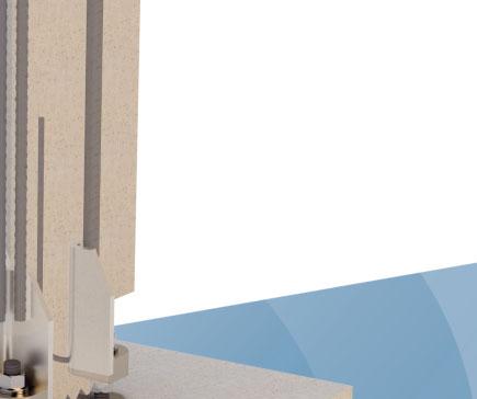
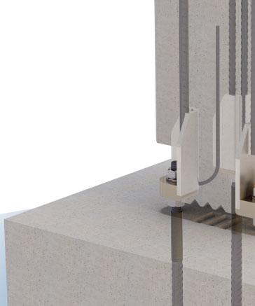
19 Annex B - Supplementary reinforcement in the column Installation of HPKM HPM-EQ connection Operations at precast factory Identification of HPKM Column Shoes Three different sizes of HPKM Column Shoes (24, 30 and 39) can be used to design HPKM HPM-EQ connection for seismic applications. The model of HPKM Column Shoes can be identified by the name in the label on the product and also according to the color of the product. Color code is marked on the base surface of column shoe s bottom plate according to the table hereafter. Color codes of recess boxes are corresponding to the color codes of HPKM Column Shoes. HPKM Column Shoes color codes. Column Shoe Corner recess Middle recess Color code HPKM 24 HPKM 24 CBOX HPKM 24 MBOX Gray HPKM 30 HPKM 30 CBOX HPKM 30 MBOX Green HPKM 39 HPKM 39 CBOX HPKM 39 MBOX Orange Installation of HPKM Column Shoes The HPKM Column Shoes are placed into the reinforcement of the column and fixed through their base plates to the end plate of the mold with recess boxes. Installation tolerance of column shoe in crosswise direction of the column is ± 2 mm. Supplementary reinforcement must be placed at the area of column base, according to Annex B. After casting the column, boxes are removed from shoes and voids are checked that they are clean from concrete. Additional information about installation of recess boxes can be found in the Technical Manual HPKM Column Shoe. Welding of the external stirrup After assembling column reinforcing cage together with column shoes, a spot-welded external stirrup has to be placed along the chamfer of the column shoes according to Table 5. Spot welds secure the stirrup to the corner column shoes to prevent any movement during the casting phase. Version: Peikko Group 09/


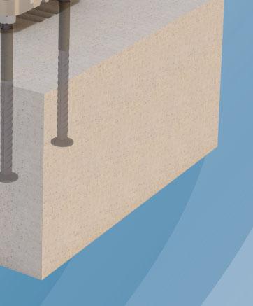
20 Installation HPKM HPM-EQ connection Positioning of the profiling plate A profiling plate has to be placed to the end plate of the mold of the column. The use of a plate with a minimum number of 4 keys per direction is mandatory in order to achieve at least 3 mm roughness at about 40 mm spacing or an indented surface. Peikko can provide tailored design of the profiling plate for specific column cross-section and HPKM Column Shoes arrangement. Peikko can offer profiling plates assembled with standard components which can be reused for different casting. Please contact Peikko s Customer Engineering Service in case of help. Concreting of the column by adopting Peikko s profiling plate. 20 Bolted Column Connection


21 Installation HPKM HPM-EQ connection Operations at construction site Identification of HPM-EQ Anchor Bolts Three different sizes of HPM-EQ Anchor Bolts (24, 30 and 39) are available for seismic applications. The model of HPM-EQ Anchor Bolts can be identified by the name in the label on the product and also according to the identification color of the product. Color codes are shown in the table hereafter. HPM-EQ Anchor Bolts color codes. Anchor Bolt Thread diameter [mm] Color code HPM-EQ Gray HPM-EQ Green HPM-EQ Orange Installation of HPM-EQ Anchor Bolts Bolts groups have to be centralized on the horizontal plane in exactly the right place and adjusted to the correct casting level h b given in the table below. The height level is measured from the surface of concrete, and the level tolerance is ±20 mm. Anchorage depth matches with the starting point of the heat shrink tube applied on the thread, so that the tube remains embedded in the foundation for the whole length. Effective installation method is to use the profiling plate for both positioning the anchor bolts and achieving a rough or indented surface on the top of the foundation below the column. Such profiling plate has to be symmetrical to that used for the corresponding column. Peikko can provide tailored design of the profiling plate for specific HPM-EQ arrangement. Please contact Peikko s Customer Engineering Service for support. Peikko s profiling plate is installed at height level according to t grout. HPM-EQ Anchor Bolts are fixed through the holes on the profiling plate with nuts and washers. To prevent displacement during the concreting process, the plate should be fixed securely to the supporting base by its fixing recesses at the sides. Peikko s profiling plate makes installation process easier thanks to alignment marks and middle hole, where concrete can be poured through. After casting, the profiling plate is detached and can be reused. Peikko s profiling plate for foundation elements. Version: Peikko Group 09/
22 Installation HPKM HPM-EQ connection In case customer fabricates own profiling plates, PPL Installation Templates are also available for correct positioning of the anchor bolts. For further information about PPL Installation Templates, please refer to HPM Anchor Bolt Technical Manual. Installation tolerances and protrusion of the anchor bolts from concrete. Top level of foundation Grout Installation tolerance Starting point of the heat shrink tube t grout h b Installation tolerance Anchor Bolt HPM-EQ 24 HPM-EQ 30 HPM-EQ 39 Thickness of grouting t grout [mm] Protrusion of the bolt h b [mm] Installation tolerance for the bolt [mm] ±3 ±3 ±3 Erection of the column 1. To level precast concrete column. Before erecting the column, the profiling plate is removed. Lower leveling nuts and washers are adjusted at the correct level. The column is erected directly on the pre-leveled washers and nuts. In alternative method shims are placed between anchor bolts and adjusted at the proper level. Lower leveling nuts must be leveled at least 5 mm under the top level of shims to secure that column will rest first on the shims. This method is recommended for heavier columns for easier and faster alignment of the column. 2. To align precast concrete column. The column is aligned in the vertical position by leveling nuts. It is practical to use two theodolites from different directions to ensure verticality. 3. To inject epoxy resin. When verticality is assured, the oversized hole of the column shoe is filled by epoxy resin to compensate the gap between anchor bolt and base plate. 22 Bolted Column Connection
23 Installation HPKM HPM-EQ connection Filling of the hole by epoxy resin. A Injection of epoxy resin HPM-EQ Anchor Bolt A 1:5 HPKM Column Shoe 4. To tighten the nuts and to pre-tension the anchor bolts. Upper nuts and washers are screwed on the bolts. First nuts are snug tightened, i.e. bolts, washers and base plates are pulled into firm contact and all of the bolts in the joint have been tightened sufficiently to prevent the removal of the nuts without the use of a wrench. Afterwards anchor bolts are pre-tensioned by applying an additional rotation to the upper nuts with the use of a long wrench. The additional rotation angles and tolerances are listed in the table below depending on bolt dimensions. Snug tightening and additional rotation of the nuts. Anchor Bolt Additional rotation angles Rotation tolerance HPM-EQ ±10 HPM-EQ ±10 HPM-EQ ±10 Snug tightening Additional rotation Final position 5. To grout joint and recesses. Before loading the column by any other structures e.g. beams or columns, the joint underneath the column and bolt recesses must be grouted by following instructions of the grout supplier. The grout must be fiber reinforced, non-shrink grade and strength at least 30% higher than the highest grade of concrete used in the connected elements. To avoid air being trapped in the joint, it is recommended to pour grout from one side of the column only. Grouting formwork is made so that adequate concrete cover for column shoes and anchor bolts is achieved. A minimum collar thickness of 20 mm should be provided around the column. After grout has reached sufficient strength, the connection is finalized and joining structures may be erected on the column. Version: Peikko Group 09/


24 Installation HPKM HPM-EQ connection On site installation step by step After positioning the anchor bolts and the profiling plate, the foundation is casted. Column is installed directly on the pre-leveled washers and nuts. Epoxy resin is injected into the column shoe hole around the anchor bolt. 24 Bolted Column Connection


25 Installation HPKM HPM-EQ connection Upper nuts and washers are screwed on the bolts and anchor bolts are pre-tensioned. After the nuts are tightened, the crane can be released. Formwork for grouting joint and recesses. Finalized connection after the grout has hardened. Version: Peikko Group 09/
26 Notes 26 Bolted Column Connection
27 Technical Manual Revisions Version: PEIKKO GROUP 09/2016. Revision:001* New cover design for 2018 added. Version: Peikko Group 09/
28 Resources DESIGN TOOLS Use our powerful software every day to make your work faster, easier and more reliable. Peikko design tools include design software, 3D components for modeling programs, installation instructions, technical manuals and product approvals of Peikko s products. peikko.com/design-tools TECHNICAL SUPPORT Our technical support teams around the world are available to assist you with all of your questions regarding design, installation etc. peikko.com/technical-support APPROVALS Approvals, certificates and documents related to CE-marking (DoP, DoC) can be found on our websites under each products product page. peikko.com/products EPDS AND MANAGEMENT SYSTEM CERTIFICATES Environmental Product Declarations and management system certificates can be found at the quality section of our websites. peikko.com/qehs