Investigation of the April 19, 2018, Communication Tower Collapse in Fordland, Missouri.
|
|
|
- Quentin West
- 5 years ago
- Views:
Transcription

1 Investigation of the April 19, 2018, Communication Tower Collapse in Fordland, Missouri. U.S. Department of Labor Occupational Safety and Health Administration Directorate of Construction October 2018
2 Report Investigation of the April 19, 2018, Communication Tower Collapse in Fordland, Missouri. October 2018 Report Prepared by Bryan D. Ewing, Ph.D., P.E. Mohammad Ayub, P.E., S.E. Office of Engineering Services Directorate of Construction 2
3 TABLE OF CONTENTS Executive Summary...5 Introduction...7 Incident Description...10 Observations of Collapsed Tower...11 Structural Analysis and Discussion...14 Conclusion...19 Appendix A Erection Drawings...20 Appendix B Fabrication Drawings...34 Appendix C Photographs (April 23, 2018)...50 Appendix D Photographs (August 1, 2018)
4 LIST OF FIGURES Figure 1. Project Location... 5 Figure 2. Typical Bracing Elevation of Tower Legs... 8 Figure 3. Typical Tower Cross Section... 8 Figure 4. Tower Elevation (TCI Structural Analysis Report Appendix E-1)... 9 Figure 5. Collapsed Communication Tower (Google Image Search) Figure 6 Top Section of Collapsed Communication Tower Figure 7. Recovered Section of the Tower 90' 120' Figure 8. Bent Tower Leg from the Recovered Section Figure 9. Bent Redundant Member at 105' Tower Elevation Figure 10. New bolts Installed on Two Diagonals at 100' Tower Elevation Figure 11. Missing bolts at the 105' Tower Elevation Figure 12. Representative Section from the Top of the Tower Figure 13. Bolted Connection between Diagonals and Redundant Horizontal Figure 14. TCI Diagonal Replacement (E-5) Figure 15. Lemay Come-a-long Used On-site Figure 16. T-532D Come-a-long in Debris Figure 17. T-532D Come-a-long Salvage from Debris Figure 18. TCI Temporary Frame Requirements (E-5)

5 Executive Summary On April 19, 2018, an incident occurred in Fordland, Missouri where one employee was killed. The project involved the reinforcement of the KOZK 1,891-foot-tall guyed communication tower along Highway FF just north of Fordland, Missouri. The location of the tower is shown in Figure 1 (905 State Highway FF Fordland, MO 65602). The tower was initially designed and erected by Kline in Currently, Missouri State University (MSU) contracted Tower Consultants, Inc. (TCI) to design the required structural modifications necessary to support the transmission line replacement. TCI s scope of work involved creating construction documents, reviewing submittal drawings, observing the construction process including producing progress reports and assisting MSU in the bidding and contractor selection process. MSU selected Steve Lemay, LLC (Lemay) to serve as the contractor. Figure 1. Project Location The Occupational Safety and Health Administration s (OSHA) Regional Administrator, Region VII, asked the Directorate of Construction (DOC) in OSHA s National Office in Washington, D.C., to provide technical and engineering assistance to the OSHA Kansas City Area Office in its investigation of the tower collapse in Fordland, MO. At your request an engineer from DOC, Dr. Bryan Ewing, P.E., accompanied by Chester Ray, visited the incident site on April 23, 2018 and August 1, We also reviewed photographic evidence, witness interviews, construction documents, industry standards and engineering reports in preparation of this report. Attached is our report. After reviewing the documents and conducting independent structural analysis, we conclude the following: 1) TCI s suggested diagonal replacement procedure was flawed in that it compromised the effectiveness of the integrated surrounding braces and the load bearing capacity of the 5
6 tower legs. A single diagonal brace could not be removed without affecting the integrity of the redundant brace because the braces share two common bolts at the diagonal/redundant connection. 2) The cause of the communication tower collapse was the weakening of the compressive strength of the tower legs by removing the bolts at the connection of the diagonals to the horizontal redundant. The compromised redundant effectively doubled the unbraced length of the tower leg which reduced the compressive capacity of the tower leg. 3) Lemay used an undersized come-a-long while removing the diagonal braces. 4) Lemay failed to provide the design of the required temporary frame for diagonal replacement above or below a guy level. TCI failed to confirm the use/design of a temporary frame as TCI is required to approve the adequacy of the temporary frame prior to diagonal replacement according to TCI s construction documentation. 6
7 Introduction The 1,891-foot-tall guyed communication tower is constructed of 10-foot wide triangular sections. The legs of the tower consisted of 63 sections of solid round steel ranging in diameter from 4½" to 3¼" that were approximately 30 feet long. The lower 34 leg sections were constructed from high strength alloy steel with a design yield strength of 95 ksi. The design yield strength of the remaining leg sections was 47 ksi. The legs are connected by numerous angle struts, solid rod diagonals and horizontal redundants as shown in Figure 2. Although Figure 2 only shows one side, all three sides of the tower are similar. The angle struts consisted of double back-to-back A36 grade steel angles. The sizes of the angles vary and were either L3x2x¼ or L2½x2x¼. The solid rod diagonals were fabricated from A36 grade steel and vary in diameter from ¾" to 1¼". The horizontal redundants were 1¾" diameter solid A36 steel rods. The horizontal redundants were narrowed at its mid-span to accommodate the splice plates of the crossing diagonals. Both diagonals and the redundant were secured to each other with two through bolts. Note that Figure 2 shows the recommended split pipe reinforcement of the tower legs, but these split pipe reinforcements were not in place at the time of the incident. The 30-foot tower leg sections were field spliced together with six A325 bolts through factory fabricated flange plates at each end of the leg. The tower was stabilized by nine levels of guy wires. Each level had three guy lines (1 for each of the principal triangular directions of the tower). The diameter of the guy lines varied from 1 1/16" to 1 9/16" with a range of initial tensile forces between ±15 kips to ±33 kips depending on the temperature. A typical cross section of the tower and tower elevation are shown in Figures 3 and 4, respectively. 7
8 30' Typical Investigation of the April 19, 2018, Communication Diagonal Redundant Double Angle Figure 2. Typical Bracing Elevation of Tower Legs Figure 3. Typical Tower Cross Section 8
9 Diagonal Replacement at Time of Failure (105' Elevation) Figure 4. Tower Elevation (TCI Structural Analysis Report Appendix E-1) 9

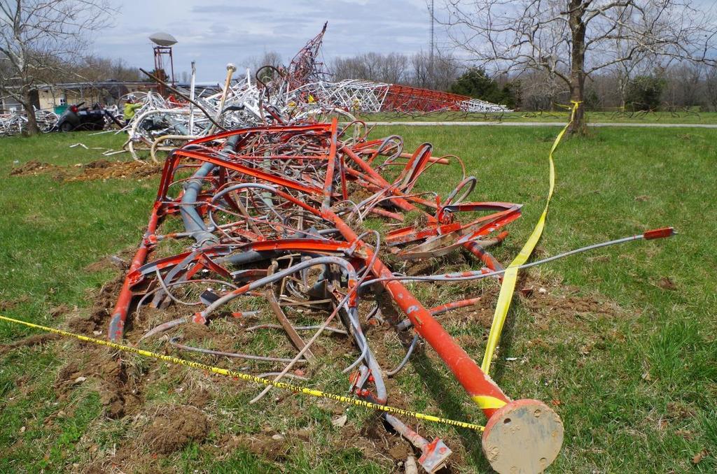
10 TCI s May 19, 2017 structural analysis of the communication tower concluded that structural modifications were necessary for the tower to comply with the wind and ice loading requirements of ANSI/TIA-222-G. TCI recommended to replace one level of guy wires, reinforce 34 tower leg sections, replace 25 bays of diagonals and reinforce one level of horizontal struts. Lemay was contracted to perform the recommended structural modifications. Incident Description On April 19, 2018 at 9:33 AM, according to security camera surveillance footage, the KOZK communication tower collapsed resulting in the fatality of one worker and non-life-threatening injuries to four others. Lemay was performing structural modifications to the tower at the time of the collapse. An image of the resulting debris is shown in Figure 5. The contractor was replacing diagonals at the 105-foot level of the 1891-foot tall communication tower when the tower started to collapse. According to witness statements, the foreman of the five-man crew instructed the other employees on the tower to descend when audible structural distresses indicated the loss of structural integrity of the tower. The other employees on the tower managed to reach the ground and retreat from the falling debris. The foreman, however, decided to remain on the tower to discern and rectify the cause of the audible structural distresses and was struck and killed by the falling structure. Figure 5. Collapsed Communication Tower (Google Image Search) 10
11 Figure 6 Top Section of Collapsed Communication Tower Lemay arrived on-site on Monday, April 16, 2018 to begin working on the structural modifications to the communication tower the next day. The first two days involved preparation of the materials and tools and laying down and painting diagonals. Work on the tower was originally going to take place on Wednesday, but high winds caused the crew to delay work on the tower for another day. The crew began replacing diagonals on Thursday, April 19, They began replacing the diagonals at the 105' elevation. According to witness statements, the six replacement diagonals, the necessary equipment and the foreman were raised in a manbasket. One employee remained on the ground and the remaining employees went to assist with the replacement of diagonals. Two of the diagonals did not fit and were returned to the staging area on the ground so that the bolt holes could be bored out to facilitate their installation. The crew completed the diagonal replacement on two of the three sides and started work on the third. Witnesses stated they began hearing unusual sounds above them and the foreman instructed the other crew members to descend the tower as quickly as possible. The crew members made it off the tower before the collapse. However, the foreman did not, resulting in the lone fatality of the incident. Observations of Collapsed Tower As shown in Figure 5, it appears that as the tower began to collapse onto itself, the tower initially fell in the southern direction. Then the tower tilted and fell over itself back in a northern direction. As the top tiers of the tower fell, they remained essentially intact. As shown in Figure 11


12 6, all the guy wires disengaged from their anchor points and whipped about slashing through tree limbs and fencing. The man-basket, original and new diagonals and tools, including two comea-longs were buried under the wreckage. The tower section from 90' to 120' was recovered and stored on-site for further observation. This tower section is shown in Figures 7 to 10. The slings and diagonals were found at the 105' tower elevation as shown in Figure 11. Several wires of the sling used for the come-a-long attachment to the tower panel point was severed and others were bird-nesting. A total of six bolted connections were missing. Two bolts were missing at the connection point between the two diagonals and the redundant horizontal bar. Two more bolts were missing from each gusset plate at the connection between the tower legs at the 100' elevation of the diagonals (see Figure 11). This was consistent with witness statements that the crew was working on the final third bay of diagonals at the 105' elevation at the time of the incident. The redundant bar and the tower leg appeared to have buckled. Figure 7. Recovered Section of the Tower 90' 120' Figure 9. Bent Redundant Member at 105' Tower Elevation Figure 8. Bent Tower Leg from the Recovered Section Figure 10. New bolts Installed on Two Diagonals at 100' Tower Elevation 12
13 Two missing bolts at each location Figure 11. Missing bolts at the 105' Tower Elevation Structural Analysis and Discussion A guyed communication tower is a slender structure that relies on the guy wires to minimize flexural stresses generated by lateral loads, including wind, earthquake, etc. The tensioned guy wires were attached to the structure at various locations along the height of the tower. The compressive gravity loads, arising from its own weight, weight of the antennas and other equipment and resultant vertical loads of the guy wires, are supported by the axial strength of the tower. One of the characteristics of a structural member that affects its compressive strength is the unbraced length of the member. Therefore, it is critical that the tower legs are adequately braced while renovations or structural modifications are underway. Bracing must be in place to ensure the compressive stability of the tower legs and the lateral stability of the tower itself. The compressive capacity of a structural member is inversely proportional to the unbraced length. Typically, as the unbraced length of a member is increased, the compressive capacity of the member is reduced. A representative section of the 105' tower elevation is shown in Figure 12. Figure 12 is a photograph of one of the tower bays of the top section of the tower that remained essentially intact after the collapse. The tower legs are braced by the diagonal rod members and the horizontal (appears vertical in the photograph as the tower is on its side) redundant. The typical tower bay is 10' wide by 10' tall. Therefore, this configuration of the bracing members creates unbraced lengths of five feet for the tower legs and redundant. The diagonals and the redundant were connected with two bolts at their mid-span as shown in Figure


14 Figure 12. Representative Section from the Top of the Tower Figure 13. Bolted Connection between Diagonals and Redundant Horizontal TCI s erection drawings states that the diagonals must be replaced one at a time. However, in order to replace a diagonal, the two bolts on each end of the diagonal and the two bolts at the diagonal s mid-span must be removed. The removal of the bolts at the mid-span, however, results in doubling the unbraced length of the tower legs and redundant from five to ten feet. 15
15 This doubling of the unbraced length creates three problems for the redundant member. First, the redundant member exceeds the allowable slenderness ratio for main compression members other than leg members and for secondary members (200 and 250 respectively) as outlined in ANSI/TIA-222-G. The resultant slenderness ratio of the redundant member without the bolted connection at its mid-span is 274. Second, the unfactored compressive resistance is reduced from 32 kips to 8 kips. This 75% reduction of compressive strength created the third problem for the redundant member. The redundant no longer satisfied the ANSI/TIA-222-G requirement for minimum bracing resistance for the tower legs. ANSI/TIA-222-G requires that the strength of the brace is at least 1.5% of the axial design compressive force of the supported member. Therefore, the unbraced length of the tower legs has doubled to ten feet. The ANSI/TIA-222-G design strength of the tower legs was reduced by 68% due to the doubling of the unbraced length. The tower legs require a minimum bracing resistance of approximately 13 kips. However, the horizontal redundant member is only capable of providing 8 kips. The resultant unfactored design strength of the tower legs reduces from 865 kips to 279 kips. The total dead load from the guy wires and the weight of the tower above the 105-foot elevation is 316 kips. Furthermore, any incidental wind load would increase the compressive load on some of the tower legs. The overstressing of the tower legs could have been a reason for why some of the diagonals did not fit and required re-boring of the bolt holes. The diagonal replacement procedure is described on sheet E-5 of TCI s erection drawings document and is partially shown in Figure 14. The diagonal replacement procedure requires the use of a come-a-long to eliminate the tensile forces in the diagonal to facilitate the removal of the diagonal. TCI requires the use of a come-a-long with a ten-ton capacity. However, Lemay used a come-a-long device (Griphoist/Tirfor T-532D) with a rated working load of 8,000 pounds (4 tons). An identical model come-a-long used on-site is shown in Figure 15. The come-a-long used on the tower is shown in Figure 16 while in the debris field and which was recovered later is shown in Figure
 Figure 15.")
16 Figure 14. TCI Diagonal Replacement (E-5) Figure 15. Lemay Come-a-long Used On-site 17


17 Figure 16. T-532D Come-a-long in Debris Figure 17. T-532D Come-a-long Salvage from Debris TCI s erection drawings document requires the use of a temporary frame when a diagonal is replaced above or below a guy wire location. Furthermore, TCI requires that the frame, provided by Lemay, be approved by TCI. During an interview with TCI engineering staff, TCI stated that they had no communications with Lemay about the use or design of a temporary frame. Lemay should have submitted a temporary frame design to TCI since diagonals required replacement 18
18 above guy wire levels 3, 4 and 5. Reciprocally, TCI should have requested a temporary frame design from Lemay since TCI s diagonal replacement procedure requires them to approve the frame. The notes from sheet E-5 of TCI s erection documents is shown in Figure 18. The lack of the temporary frame design did not contribute to the collapse of the communication tower, because at the time of the incident Lemay was not working on a bay that required a temporary frame. Figure 18. TCI Temporary Frame Requirements (E-5) Conclusion Based upon the above, we conclude that: 1) TCI s suggested diagonal replacement procedure was flawed in that it compromised the effectiveness of the integrated surrounding braces and the load bearing capacity of the tower legs. A single diagonal brace could not be removed without affecting the integrity of the redundant brace because the braces share two common bolts at the diagonal/redundant connection. 2) The cause of the communication tower collapse was the weakening of the compressive strength of the tower legs by removing the bolts at the connection of the diagonals to the horizontal redundant. The compromised redundant effectively doubled the unbraced length of the tower leg which reduced the compressive capacity of the tower leg. 3) Lemay used an undersized come-a-long while removing the diagonal braces. 4) Lemay failed to provide the design of the required temporary frame for diagonal replacement above or below a guy level. TCI failed to confirm the use/design of a temporary frame as TCI is required to approve the adequacy of the temporary frame prior to diagonal replacement according to TCI s construction documentation. 19
19 Appendix A ERECTION DRAWINGS (PREPARED BY TCI) 20

20 21 Investigation of the April 19, 2018, Communication

21 22 Investigation of the April 19, 2018, Communication

22 23 Investigation of the April 19, 2018, Communication
23 24 Investigation of the April 19, 2018, Communication
24 25 Investigation of the April 19, 2018, Communication
25 26 Investigation of the April 19, 2018, Communication
26 27 Investigation of the April 19, 2018, Communication

27 28 Investigation of the April 19, 2018, Communication

28 29 Investigation of the April 19, 2018, Communication
29 30 Investigation of the April 19, 2018, Communication
30 31 Investigation of the April 19, 2018, Communication

31 32 Investigation of the April 19, 2018, Communication

32 33 Investigation of the April 19, 2018, Communication
33 Appendix B FABRICATION DRAWINGS (PREPARED BY TCI) 34
34 35 Investigation of the April 19, 2018, Communication
35 36 Investigation of the April 19, 2018, Communication
36 37 Investigation of the April 19, 2018, Communication
37 38 Investigation of the April 19, 2018, Communication
38 39 Investigation of the April 19, 2018, Communication
39 40 Investigation of the April 19, 2018, Communication
40 41 Investigation of the April 19, 2018, Communication
41 42 Investigation of the April 19, 2018, Communication
42 43 Investigation of the April 19, 2018, Communication
43 44 Investigation of the April 19, 2018, Communication
44 45 Investigation of the April 19, 2018, Communication
45 46 Investigation of the April 19, 2018, Communication
46 47 Investigation of the April 19, 2018, Communication
47 48 Investigation of the April 19, 2018, Communication
48 49 Investigation of the April 19, 2018, Communication
49 Appendix C PHOTOGRAPHS (APRIL 23, 2018) 50


50 Figure C- 1 Figure C- 2 51


51 Figure C- 3 Figure C- 4 52


52 Figure C- 5 Figure C- 6 53


53 Figure C- 7 Figure C- 8 54

54 Figure C- 9 Figure C


55 Figure C- 11 Figure C


56 Figure C- 13 Figure C
57 Appendix D PHOTOGRAPHS (AUGUST 1, 2018) 58

58 Figure D- 1 Figure D- 2 59


59 Figure D- 3 Figure D- 4 60


60 Figure D- 5 Figure D- 6 61


61 Figure D- 7 Figure D- 8 62


62 Figure D- 9 Figure D


63 Figure D- 11 Figure D