GEOTECHNICAL INVESTIGATION PROPOSED OUTFALL LOCATION CITY OF MORGAN S POINT DRAINAGE HARRIS COUNTY, TEXAS REPORT NO
|
|
|
- Joseph Jones
- 5 years ago
- Views:
Transcription
1
2
3
4
5 GEOTECHNICAL INVESTIGATION PROPOSED OUTFALL LOCATION CITY OF MORGAN S POINT DRAINAGE HARRIS COUNTY, TEXAS REPORT NO Reported to: SIRRUS ENGINEERS, INC. Houston, Texas Submitted by: GEOTEST ENGINEERING, INC. TBPE Registration No. F-410 Houston, Texas Key Map No. 541 W
6
7 TABLE OF CONTENTS Page SUMMARY INTRODUCTION 1.1 Project Description Geotechnical Investigation Program FIELD INVESTIGATION 2.1 General Geotechnical Borings LABORATORY TESTING SITE AND SUBGRADE CHARACTERIZATION 4.1 Site Geology Soil Stratigraphy Groundwater DESIGN CRITERIA AND RECOMMENDATIONS 5.1 General Open-Cut Excavation Geotechnical Parameters Excavation Stability Groundwater Control Storm Sewer Bedding and Backfill Structures Description Foundation Conditions Foundation Design Recommendations Protection of Below Grade Structures Groundwater Control During Construction Structure Backfill PROVISIONS... 14
8 ILLUSTRATIONS Figure Vicinity Map... 1 Plan of Borings... 2 Boring Log Profile... 3 Symbols and Abbreviations Used on Boring Log Profile... 4 Trench Support Earth Pressure and 5.2 Stability of Bottom for Braced Cut... 6 Lateral Earth Pressure Diagram for Permanent Wall and 7.2 Uplift Pressure and Resistance... 8 TABLES Table Summary of Boring Information... 1 Geotechnical Design Parameter Summary: Open-cut Excavation... 2 APPENDIX A Figure Log of Borings... A-1 and A-2 Symbols and Terms Used on Boring Logs... A-3 APPENDIX B Figure Grain Size Distribution Curves... B-1
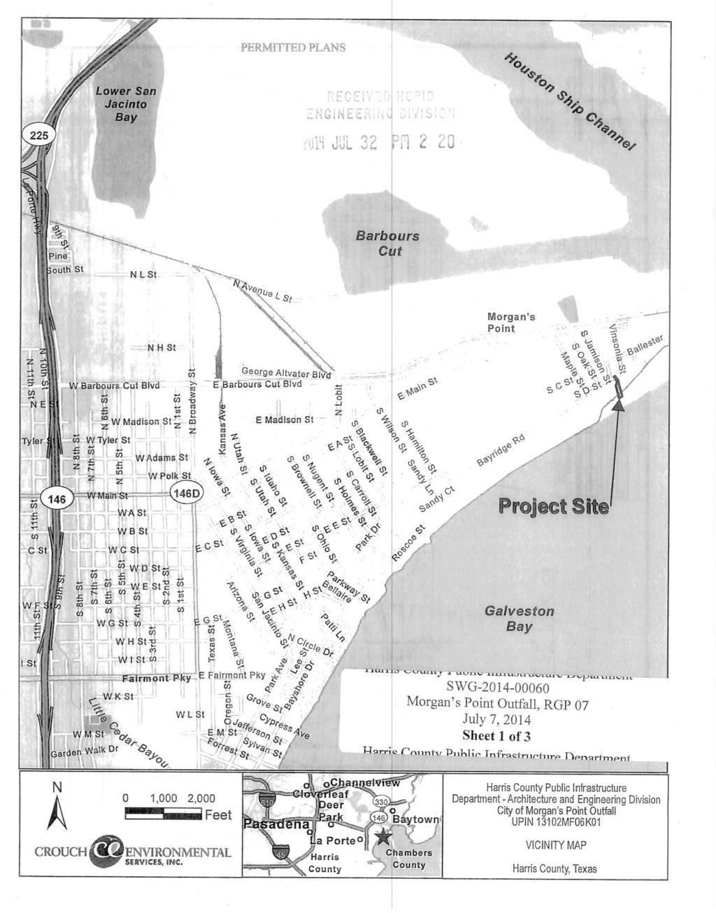
9 Geotest Engineering, Inc. Report No Proposed Outfall Location City of Morgan s Point Drainage March 6, 2014 Harris County, Texas SUMMARY A geotechnical investigation was conducted for a proposed City of Morgan s Point Outfall in Harris County, Texas. The project includes design and construction of 144 LF of 48-inch diameter RCP storm sewer outfall and 205 LF of 2-4 x2 RCB connecting from an existing storm sewer manhole leading south into the Galveston Bay which includes the installation of a new manhole at Sta and a junction box at Sta The proposed storm sewer will be installed by open cut method of construction. The depth of proposed storm sewers ranges from 4 to 10 feet deep. This study included drilling and sampling a total of two (2) soil borings one to a depth of 15 feet, and the second to a depth of 16 feet and performing laboratory tests on samples recovered from borings, performing engineering analyses and preparing a geotechnical report. The principal findings and conclusions developed from this investigation are summarized as follows: The subsurface soils as encountered in borings GB-1 and GB-2 consists of soft to very stiff gray and brown fat clay, lean clay with sand and sandy lean clay to a depth of 15 and 16 feet below the existing ground. Medium dense gray and brown silty sand and sandy silt was encountered in boring GB-2 between the depths of 2 feet and 12 feet. Free water was first encountered at depth of 1.5 feet in boring GB-2 during drilling. The water level measured 20 minutes after water was first encountered, was at depth of 1.5 feet in boring GB-2. No ground water was encountered in boring GB-1 drilled for this study. The bedding and backfill for storm sewers should be as per the Harris County Standard Specifications Item No
10 Geotest Engineering, Inc. Report No Proposed Outfall Location City of Morgan s Point Drainage March 6, 2014 Harris County, Texas The foundation recommendations for the manholes and junction box are presented in Section 5.3 of this report. 2
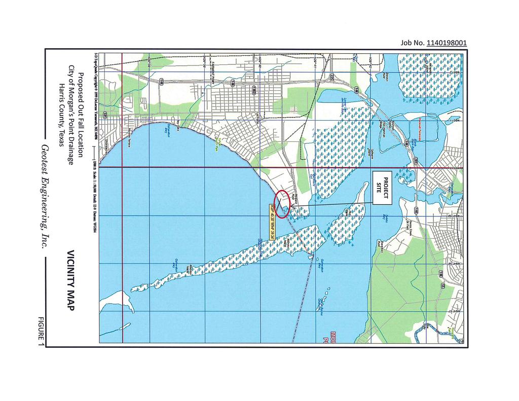
11 Geotest Engineering, Inc. Report No Proposed Outfall Location City of Morgan s Point Drainage March 6, 2014 Harris County, Texas 1.0 INTRODUCTION 1.1 Project Description The project includes design and construction of 144 LF of 48-inch diameter RCP storm sewer outfall and 205 LF of 2-4 x2 RCB connecting from an existing storm sewer manhole leading south into the Galveston Bay which includes the installation of a new manhole at Sta and a junction box at Sta The proposed storm sewers will be installed by open cut method of construction. The depth of proposed storm sewers ranges from 4 to 10 feet deep. A Vicinity Map is presented on Figure Geotechnical Investigation Program The purpose of this investigation was to evaluate the soil and groundwater conditions along proposed 48-inch diameter RCP and 2-4 x2 RCB storm sewer alignment and to provide geotechnical recommendations for the proposed storm sewers construction. The scope of this investigation consists of the following tasks. Drill and Sample: two (2) soil borings to a depth of 15 and 16 feet. Perform laboratory tests on selected representative soil samples to determine the engineering properties of the soils and to select design soil parameters; Perform engineering analyses in accordance with Harris County Design Standards to develop geotechnical recommendations for bedding and backfill, bottom stability, groundwater control requirements and construction consideration for storm sewers construction; and Prepare a geotechnical report. 3
12 Geotest Engineering, Inc. Report No Proposed Outfall Location City of Morgan s Point Drainage March 6, 2014 Harris County, Texas 2.0 FIELD INVESTIGATION 2.1 General After obtaining the utilities clearance of proposed two (2) marked soil borings in the field, borings were drilled to the explored depths utilizing a truck mounted drilling rig. All the drilling and sampling were performed in accordance with appropriate ASTM procedures. 2.2 Geotechnical Borings Subsurface conditions were explored by drilling and sampling two (2) soil borings (designated as GB-1 and GB-2) to depths of 15 feet and 16 feet respectively. The approximate boring locations are shown on Figure 2, Plan of Borings. Survey information (Northing and Easting coordinates and ground surface elevation) of completed borings is provided to us by Sirrus Engineers, Inc. The summary of boring information is presented in Table 1. In general, samples were obtained continuously to the termination depths in both GB-1 and GB-2. Cohesive soils were obtained with a 3-inch thin-walled tube sampler in general accordance with ASTM Method D 1587 and samples of granular soils were sampled with a 2-inch split-barrel sampler in accordance with ASTM Method D Each sample was removed from the sampler in the field, carefully examined and then logged by an experienced soils technician. Suitable portions of each sample were sealed and packaged for transportation to Geotest s Laboratory. The shear strength of cohesive soil samples was estimated using a pocket penetrometer in the field. Driving resistances for the split-barrel sampler in granular soils, recorded in the field as "blows per foot, are indicated on the boring logs. All the borings were grouted with cement-bentonite grout after completion of drilling and obtaining water level measurements. 4
13 Geotest Engineering, Inc. Report No Proposed Outfall Location City of Morgan s Point Drainage March 6, 2014 Harris County, Texas Detailed descriptions of the soils encountered in the borings are given on the boring logs presented on Figures A-1 and A-2 in Appendix A. A key to symbols and terms used on boring logs is given on Figure A-3 in Appendix A. 5
14 Geotest Engineering, Inc. Report No Proposed Outfall Location City of Morgan s Point Drainage March 6, 2014 Harris County, Texas 3.0 LABORATORY TESTING The laboratory testing program was designed to evaluate the pertinent physical properties and shear strength characteristics of the subsurface soils. Classification tests were performed on selected samples to aid in soil classification. Undrained shear strengths of selected cohesive samples were measured by unconfined compression (ASTM D 2166) and unconsolidated undrained (UU) triaxial compression tests (ASTM D 2850). The results of the unconfined compression and UU triaxial compression tests are plotted on the boring logs as solid circles and squares, respectively. The shear strength of cohesive samples was measured in the field with a calibrated hand pocket penetrometer and also in the laboratory with a Torvane. The shear strength values obtained from the penetrometer and Torvane are plotted on the boring logs as open circles and triangles, respectively. Measurements of moisture content and dry unit weight were taken for each UU triaxial and unconfined compression test sample. Moisture content (ASTM D 2216) measurements were also made on other samples to define the moisture profile at each boring location. The liquid and plastic limit tests (ASTM D 4318) and percent passing No. 200 sieve (ASTM D 1140) were performed on appropriate samples. A sieve analysis (ASTM D422) is also performed on selected cohesionless soil sample to evaluate grain size distribution. The result of all tests are tabulated or summarized on the boring logs presented on Figures A-1 through A-2 in Appendix A. The grain size distribution curves are presented on Figure B-1 in Appendix B. 6
15 Geotest Engineering, Inc. Report No Proposed Outfall Location City of Morgan s Point Drainage March 6, 2014 Harris County, Texas 4.0 SITE AND SUBGRADE CHARACTERIZATION 4.1 Site Geology The project site lies in Beaumont Formation. The clays and sands of the Beaumont Formation are over-consolidated as a result of desiccation from frequent rising and lowering of the sea level and the groundwater table. Consequently, clays of this formation have moderate to high shear strength and relatively low compressibility. The sands of the Beaumont Formation are typically very fine and often silty. There is evidence in the Houston area of the occurrence of cemented material (sandstone and siltstone) deposits within this formation. 4.2 Soil Stratigraphy Based on the subsurface soils encountered in the boreholes, one (1) boring log profile was developed and is presented on Figure 3. To the left of each boring shown on the profile is an indication of the consistency of each stratum. More than one consistency for an individual stratum indicates that the consistency is different at different depths within the stratum. For cohesive soils, consistency is related to the undrained shear strength of the soil and for granular soils, the consistency is related to the relative density of the soil. To the right of each boring shown on the profile is the overall classification of the soil contained within each stratum. The symbols and abbreviations used on the boring log profile are given on Figure 4. The soil classification is based on ASTM Standards. The subsurface soils as encountered in borings GB-1 and GB-2 consists of soft to very stiff gray and brown fat clay, lean clay with sand and sandy lean clay to a depth of 15 and 16 feet below the existing ground. Medium dense gray and brown silty sand and sandy silt was encountered in boring GB-2 between the depths of 2 feet and 12 feet. The fat clay is of high plasticity with a liquid limit of about 61 and a plasticity index of about 37. The lean clay with sand and sandy lean clay is of medium to high plasticity with liquid limits 7
16 Geotest Engineering, Inc. Report No Proposed Outfall Location City of Morgan s Point Drainage March 6, 2014 Harris County, Texas ranging from 26 to 43 and plasticity indices ranging 10 to 25. The percent fines (passing No. 200 sieve) of fat clay is about 92 percent. The percent fines of lean clay with sand is about 74 percent and the percent fines of sandy lean clay is about 63 percent. The percent fines of silty sand is about 39 percent and the percent fines of sandy silt is about 67 percent. 4.3 Groundwater Free water was first encountered at depth of 1.5 feet in boring GB-2. The water level measured 20 minutes after water was first encountered, was at depth of 1.5 feet in boring GB-2. No ground water was encountered in boring GB-1 drilled for this study. It should be noted that various environmental and man-made factors such as amount of precipitation and changes in water level in the bay, could substantially influence groundwater level. 8
17 Geotest Engineering, Inc. Report No Proposed Outfall Location City of Morgan s Point Drainage March 6, 2014 Harris County, Texas 5.0 DESIGN CRITERIA AND RECOMMENDATIONS 5.1 General The project includes design and construction of 144 LF of 48-inch diameter RCP storm sewer outfall and 205 LF of 2-4 x2 RCB connecting from an existing storm sewer manhole leading south into the Galveston Bay which includes the installation of a new manhole at Sta and a junction box at Sta The proposed storm sewers will be installed by open cut method of construction. The depth of proposed storm sewers ranges from 4 to 10 feet deep. 5.2 Open-Cut Excavation Geotechnical Parameters. Based on the soil conditions revealed by the borings GB-1 and GB-2, geotechnical parameters were developed for the design of storm sewers along the proposed alignment. The geotechnical design parameters are provided in Table 2. For design, the groundwater level should be assumed to exist at the ground surface, since this condition may exist after a heavy rain or flooding Excavation Stability. The open excavation may be shored, laid back to a stable slope or some other equivalent means used to provide safety for workers and adjacent structures. The excavating and trenching operations should be in accordance with OSHA Standards, OSHA 2207, Subpart P, latest revision and the Harris County requirements. Excavation Shallower Than 5 Feet Excavations that are less than 5 feet (critical height) deep should be appropriately protected when any indication of hazardous ground movement is anticipated. Excavation Deeper Than 5 Feet - Excavations that are deeper than 5 feet should be sloped, shored, sheeted, braced or laid back to a stable slope or supported by some other equivalent 9
18 Geotest Engineering, Inc. Report No Proposed Outfall Location City of Morgan s Point Drainage March 6, 2014 Harris County, Texas means or protection such that workers are not exposed to moving ground or cave-ins. The slopes and shoring should be in accordance with the trench safety requirements per OSHA Standards. The following items provide design criteria for trench stability. (i) OSHA's Soil Type. Based on the soil conditions revealed by the borings and the assumed groundwater level at surface, OSHA's soil type "C" should be used for the determination of allowable maximum slope and/or the design of a shoring system. For shoring deeper than 20 feet, an engineering evaluation is required. (ii) Excavation Support Earth Pressure. Based on the subsurface conditions indicated by this investigation and laboratory testing results, the excavation support earth pressure diagrams were developed and are presented in Figures 5.1 and 5.2. This pressure diagram can be used for the design of temporary excavation bracing. For a trench box, a lateral earth pressure resulting from an equivalent fluid with a unit weight of 92 pcf is recommended. The above value of equivalent fluid pressure is based upon an assumption that the groundwater level is near the ground surface, since these conditions may exist after a heavy rain or flooding. Effect of surcharge loads at the ground surface should be added to the computed lateral earth pressure. A surcharge load, q, will typically result in a lateral load equal to 0.5 q. (iii) Bottom Stability. In braced cuts, if tight sheeting is terminated at the base of the cut, the bottom of the excavation can become unstable under certain conditions. This condition is governed by the shear strength of the soils and by the differential hydrostatic head between the groundwater level within the retained soils and the groundwater level at the interior of the trench excavation. For cuts in cohesive soils, as predominantly encountered in boring GB-1 for the excavation depths, the stability of the bottom can be evaluated in accordance with the procedure outlined on Figure 6. In view of the presence of relatively weaker soils between the depths of 0 to 10 feet near boring GB-1, it is recommended that sheeting be carried below the base of the 10
19 Geotest Engineering, Inc. Report No Proposed Outfall Location City of Morgan s Point Drainage March 6, 2014 Harris County, Texas excavation level in reach between the borings GB-1 and GB-2 to insure the bottom stability. Further, at boring location GB-2, where silty sand was encountered below 2- ft the excavation should be performed after dewatering to avoid bottom stability problems Groundwater Control. Excavations for the proposed storm sewers may encounter groundwater seepage to varying degrees depending upon groundwater conditions at the time of construction and the location and depth of excavation. In cohesive soils, as encountered in boring GB- 1 for the excavation depths, groundwater may be managed by collection in trench bottom sumps for pumped disposal. At boring GB-2, where silty sand was encountered below the 2 feet depth, dewatering such as vacuum well points may be required to lower the ground water level at least 5 feet below the excavation. Alternatively, if dewatering cannot effectively lower the ground water level below the excavation, then a continuously interlocked (watertight) sheet piling with trench bottom sumps for pumped disposal may be installed. The contractor should verify the groundwater level at the time of construction and should provide an adequate dewatering system, where required Strom Sewer Bedding and Backfill. The bedding and backfill for storm sewer should be as per Harris County Standard Specification Item No Structures Description. The structures associated with this project will be new manholes, junction box and reinforced concrete box sewers. The maximum depth of junction box is 4 to 10 feet deep Foundation Conditions. Foundation conditions were explored by borings GB-1 and GB- 2. Based on the soil conditions revealed by the borings, junction box bases will be in medium stiff to stiff fat clay near boring GB-1 and in medium dense silty sand in boring GB-2. 11
20 Geotest Engineering, Inc. Report No Proposed Outfall Location City of Morgan s Point Drainage March 6, 2014 Harris County, Texas Foundation Design Recommendations. The following items provide recommendations and design criteria for construction of junction box. Allowable Bearing Pressures. Allowable (net) bearing pressure of 1,700 psf may be utilized for the design of manholes and junction box to be installed as part of the proposed storm sewer construction project. This allowable bearing pressure includes a safety factor of 2.0. The above recommendations assume that the final bearing surfaces consist of undisturbed natural soils and that underlying semi-transmissive zones are properly pressure-relieved and stable undisturbed bearing surfaces are attained. Bottom Stability. Bottom stability should be followed in accordance with Section (iii) of this report. Lateral Earth Pressure. The pressure diagram presented on Figure 5.1 and 5.2 can be used for the design of braced excavation. The lateral earth pressure diagram presented on Figure 7.1 and 7.2 is applicable for the design of the permanent walls. Hydrostatic Uplift Resistance. Structures extending below the groundwater level should be designed to resist uplift pressure resulting from excess piezometric head. Design uplift pressures should be computed based on the assumption that the water table is at ground surface. To resist the hydrostatic uplift at the bottom of the structure, one of the following sources of resistance can be utilized in each of the designs. a. Dead weight of structure, b. Weight of soil above base extensions plus weight of structure, or c. Soil-wall friction plus dead weight of structure. 12
21 Geotest Engineering, Inc. Report No Proposed Outfall Location City of Morgan s Point Drainage March 6, 2014 Harris County, Texas The uplift force and resistance to uplift should be computed as detailed on Figure 8. In determining the configuration and dimensions of the structure using one of the approaches presented on Figure 8, the following factors of safety are recommended. a. Dead weight of concrete structure, S f1 = 1.10, b. Weight of soil (backfill) above base extension, S f2 = 1.5, and c. Soil-wall friction, S f3 = 3.0. Friction resistance should be discounted for the upper 5 feet, since this zone is affected by seasonal moisture changes Protection of Below Grade Structures. The design of the proper means for protection of below grade structures will depend upon the potential of the aggressivity or corrosivity of soil and groundwater properties. The aggressivity testing was not within the scope of this study. The design of the protection of below grade structures is beyond the scope of services for this study Groundwater Control During Construction. Excavations for the proposed storm sewers may encounter groundwater seepage to varying degrees depending upon groundwater conditions at the time of construction and the location and depth of excavation. In cohesive soils, as encountered in boring GB-1 for the excavation depths, groundwater may be managed by collection in trench bottom sumps for pumped disposal. At boring GB-2, where silty sand was encountered below the 2 feet depth, dewatering such as vacuum well points may be required to lower the ground water level at least 5 feet below the excavation. Alternatively, a continuously interlocked (watertight) sheet piling with trench bottom sumps for pumped disposal may be installed. The contractor should verify the groundwater level at the time of construction and should provide an adequate dewatering system, where required Structure Backfill. The bedding and backfill for manholes and junction box should be in accordance with the HCPID Standard Specification Item No
22 Geotest Engineering, Inc. Report No Proposed Outfall Location City of Morgan s Point Drainage March 6, 2014 Harris County, Texas 6.0 PROVISIONS The description of subsurface conditions and the design information contained in this report are based on the test boring made at the time of drilling at specific locations. Some variation in soil conditions may however, occur between test boring. Should any subsurface conditions other than those described in our boring log be encountered, Geotest should be immediately notified so that further investigation and supplemental recommendations can be provided. The depth of the groundwater level may vary with changes in environmental conditions such as frequency and magnitude of rainfall. The stratification lines on the log of boring represent the approximate boundaries between soil types. Transitions between soil types may be more gradual than depicted. This report has been prepared for the exclusive use of Sirrus Engineers, Inc. and the Harris County Public Infrastructure Department Architecture and Engineering Division for the design and construction of City of Morgan s Point Outfall in Harris County, Texas. This report shall not be reproduced without the written permission of Geotest Engineering, Inc., Sirrus Engineers, Inc., or Harris County, Texas. 14
23
24
25
26
27
28
29
30
31
32
33
34
35
36
37
38
39
40
41
42