IMUA ANNUAL PRESENTATION 2013
|
|
|
- Cori O’Connor’
- 5 years ago
- Views:
Transcription
1 IMUA ANNUAL PRESENTATION

2 Who We Are: Founded in 1947 in Colorado Have expanded to a company of approximately 2,000 With Operations Constructing Transportation, Water and Energy Infrastructure throughout the US and Canada 2

3 Focus on Inland Bridge Construction I-35W - Minnesota 3
 Glenwood Springs,")
4 Where We Started: Glenwood Canyon Corridor (I-70) Glenwood Springs, Colorado 4


5 Sagadahoc Bridge over the Penobscot River 5


6 CAROLINA BAYS PARKWAY MYRTLE BEACH 6


7 Arthur Ravenal Bridge over the Cooper River 7

8 Alfred Zampa Memorial Bridge Over the Carquinez Straits Crockett, CA 8


9 San Francisco Oakland Bay Bridge Skyway 9

10 John James Audubon Bridge Sereno Brown, PE Deputy P.M. / Project Engineer 10


11 About the Project 11


12 Contract Details Proposal Date: January 18, 2006 NTP Date: May 4, 2006 Final Acceptance: May 5, 2011 Total Contract Value: $347,860,000 Final Contract Value: $355,901,114 12

13 Contract Team Flatiron Constructors, Inc. 54% Granite Construction, Inc. 25% Parsons 21% 13


14 Where is St. Francisville, LA 14

15 Bridge 3-3: Cable-Stayed Unit Bridge 3 15


16 Project Overview 8 Bridges Begin Bridge 3 Bridge 2 12 miles of 2-lane asphalt roadway End Bridge 3 Bridge 4 Bridge 5 1,100,000 CY of Earth Work 4 New Intersections 10+ Design Consultants Bridge 6 Bridge 7 Bridge 8 New US Hwy 61 & LA Hwy 10 Intersection Existing US Hwy 61 16
17 General Information First Design-Build project for Louisiana DOTD Furthest South in Mississippi River that drilled shafts are used to support superstructure. Other Notable Citations: 1. John James Audubon at 1,583 ft 1. Longest Cable Stay Bridge in Western Hemisphere! st Longest Cable Stay Bridge in the World 2. Cooper River at 1,546 ft (Also Constructed by FLATIRON) 1. Previous Record Holder for Longest in Western Hemisphere th Longest Cable Stay Bridge in the World 17
18 Layout of Cable Stayed Unit 18
19 General Arrangement 1583 ft Main Span 2866 ft Cable Stayed Portion 2.27 miles including approaches 19
20 Chief Obstacles to a Bridge of this Type 1. Finding an adequate foundation 1. No Rock 2. High Potential For Vessel Impact / Barge Impact 2. Contending with the Mississippi River 1. Extreme Variability in River Levels 2. Unpredictable and Potential For Rapid Change 20
21 Chief Obstacles to a Bridge of this Type 1. Finding an adequate foundation 1. No Rock 2. High Potential For Vessel Impact / Barge Impact 2. Contending with the Mississippi River 1. Extreme Variability in River Levels 2. Unpredictable and Potential For Rapid Change 21

22 Traditional Foundation Types 1. Sunken Caisson 22
23 Traditional Foundation Types 1. Sunken Caisson 23
24 Traditional Foundation Types 1. Sunken Caisson 24
25 Traditional Foundation Types 1. Sunken Caisson 25
26 Traditional Foundation Types 1. Sunken Caisson 26
27 Traditional Foundation Types 1. Sunken Caisson 27

28 Traditional Foundation Types 2. Driven Pile 28

29 Traditional Foundation Types 3. Drilled Shafts 29


30 Install Oscillator 1. Set Base 2. Set Oscillator 30


31 Excavate Temporary Casing Using Bottom of Permanent Casing 90 Temporary Casing Hammer Grabs West East

32 32 Excavate Temporary


33 Lower Cage Set Rebar Cage Upper Cage 33


34 Pour Tremie Concrete 1 Initially, Tremie pipe is set ~ 6 above base plate while concrete is pumped. 2 Once flow is established and a seal around the Tremie is formed by the concrete, the temporary casing is oscillated up, always maintaining a 10 plug. 10 Min. Embed Note: In order for casing to be extracted, a 10 Slump must be maintained for Duration of Pour (~8 hours) 34
35 Chief Obstacles to a Bridge of this Type 1. Finding an adequate foundation 1. No Rock 2. High Potential For Vessel Impact / Barge Impact 2. Contending with the Mississippi River 1. Extreme Variability in River Levels 2. Unpredictable and Potential For Rapid Change 35
36 Access to the Work 36

37 Access to the Work 37
38 Chief Obstacles to a Bridge of this Type 1. Finding an adequate foundation 1. No Rock 2. High Potential For Vessel Impact / Barge Impact 2. Contending with the Mississippi River 1. Extreme Variability in River Levels 2. Unpredictable and Potential For Rapid Change 38


39 Trestle and Work Platform Built to feed all stages of construction from drilled shafts to deck erection. East Trestle 342 ft long West Trestle 870 ft long Provided some relief from annual flood waters. 39


40 Annual Fluctuation of Mississippi River Max River Level Min River Level

41 Working on the River (Or Trying ) HIGHEST RIVER LEVEL RECORDED OVER LAST 85 YEARS NEW $2M CRANE 41

42 Working on the River (Or Trying ) 42

43 Working On the River (Or Trying ) 43

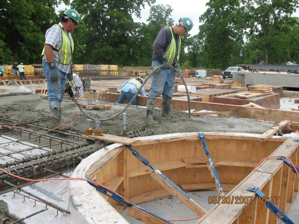
44 Foundation Construction Design & Construction of Pier Footings 44
45 Foundation Construction Design & Construction of Pier Footings THE CHALLENGE: How to construct a reinforced concrete monolith, approximately half the size of a football field, underwater. In depths that can vary from 4 to 45 below water? THE PLAN: Construct the shell of the pier, above water, then carefully submerge it into position create a waterproof seal and then remove all the water leaving a rigid empty shell to construct your pier within. BEHOLD: The Modular Cofferdam For an idea that does not first seem insane, there is no hope. Albert Einstein 45


46 Past Project Experience Bath, Maine Bath, Maine

47 Past Project Experience John s Pass, FLORIDA

48 Vetting the Design: We Built Models 48


49 Vetting the Design: We Built Models Lots of Models 49

50 Lowering Mock-Up Employee Training Even Full Scale! 50

51 Peer Design Review (Global Marketplace) Concept Peer Review Final Peer Review Project Design Check Cofferdam Design Project Locale Project Design Check 51
52 Cofferdam Erection Sequence Piles and trestle are installed 52
53 Install Soffit Panels Top View 53


54 Tower Foundations 1W & 1E 160 x 64 x 15 Cap 7 x 3 pile group 8-0 diameter shafts 54


55 Casting of Cofferdam Panels On-Site 55


56 Install Soffit Panels 56


57 Walk Through of Construction Sequence Install jacking system with permanent hangers 57

58 Install Bracing Frame Install first tier of brace frame Top View 58
59 Erect Pre-Cast Wall Install pre-cast walls Connect to soffit panels and first tier brace frame 59

60 Install Precast Wall Panels 60


61 Install Precast Wall Panels 61
62 Install Additional Brace Frames Install 2 nd and 3 rd tier brace frame. 62

63 Install Additional Brace Frames 63

64 stall Sheet iles 64

65 Finished Cofferdam Prior to Lowering 65
66 Lower Structure Synchronously lower dam from elev. +44ft to -3ft (47ft Total) 66

67 Field Jacking Arrangement 67

68 Nut Spinners At Work 68

69 Jacking Load Frames & Lowering Control Center 69

70 Lowering Control Console 70

71 Field Jack Pressure Monitoring / Digital Inclinometer M 71

72 Lower Cofferdam Structure 72

73 Lower Structure 73
74 A View From Inside the Dam 74

75 A View From Inside the Dam 75


76 Tracking Progress 76
77 Pour Concrete Seal Install 8 foot concrete seal 77
78 Dewater Structure Install pump Remove water 78
79 Remove Hangers and Cut Casing Remove hangers Cut casing 79
80 Place Reinforced Pile Cap Place reinforced pile cap concrete 80
81 Place Pedestal Concrete Place pedestal reinforcing and concrete lift 1 Restrut as required 81
82 Place Pedestal Concrete Lift 2 Place pedestal concrete lift 2 82
83 Remove Cofferdam Remove sheeting Remove bracing Patch blockouts 83

84 Lowered Cofferdam 84

85 Lowered Cofferdam BEACON 85


86 Inside Cofferdam 86

87 87 Inside Cofferdam

88 Constructing Tower Base 88

89 Designer Rendering 89
")
90 How Did We Do? (Actual Photo) 90