The San Francisco- Oakland Bay Bridge Spans: Has the Field of Bridge Engineering Regressed?
|
|
|
- Jack Johnston
- 5 years ago
- Views:
Transcription


1
2 The San Francisco- Oakland Bay Bridge Spans: Has the Field of Bridge Engineering Regressed? Abolhassan Astaneh-Asl, Ph.D., P.E., Professor And A Minner Faculty Fellow in Engineering Ethics and Social/Professional Responsibility University of California, Berkeley

3 The San Francisco- Oakland Bay Bridge Spans: Has the Field of Bridge Engineering Regressed? The answer is absolutely not. It is the lack of Engineering Ethics that causes these problems


4 A. Astaneh s Major Building Studies Projects World Trade Center Studies 54-Story L.A. Embarcadero-4, S.F. 52-story, L.A. Campanile Seismic Studies Bam, Iran Earthquake Jinta Tower, China Kobe, Japan Quake 27-Story, L.A. Century City, Qatar Sefid Rood Dam Seismic Damage Burbank Building Steel Moment Frames Pakistan Quake 4


5 A. Astaneh s Major Bridge Studies Projects Akashi-Kaikyo Golden Gate West Bay Bridge Fatih S.Mehmet -Turkey SAS Bay Bridge Higashi-Japan Rama-8, Thailand Astaneh-Black Proposal Rokko-Japan Nishinomia-Japan Auckland Harbor, NZ Carquinez East Bay Bridge Spans Richmond San Rafael Albion River Bridge Hayward San Mateo Girder Bridges I-35W Collapse I-5 Bridge Collapse 5

6 The 1937 San Francisco Oakland Bay Bridge First Version: Submitted in a letter to the Metropolitan Transportation Commission, June, This Version: Presented to the Corp of Engineers in Sacramento, June
7 Seismic Studies of the West Suspension Spans of the Bay Bridge A. Astaneh, Principal Investigator, UC-Berkeley D. McCallen, Co-PI, LLNL, and S. Larsen, Co-PI, LLNL, Funded by: UC-Berkeley and LLNL Copyright Abolhassan Astaneh- Asl/UC-Berkeley. All rights reserved. Establishing Ground Motions 7


8 Establishing Ground Motions in the Bay Area Seismic Studies of the West Suspension Spans of the Bay Bridge Copyright Abolhassan Astaneh- Asl/UC-Berkeley. All rights reserved. 8


9 Seismic Studies of the West Suspension Spans of the Bay Bridge Structural Inelastic Model Diaphragms Tower Shaft


10 Seismic Studies of the West Suspension Spans of the Bay Bridge

11 The 2013 SAS Bay Bridge under Construction First Version: Submitted in a letter to the Metropolitan Transportation Commission, June, This Version: Presented to the Corp of Engineers in Sacramento, June

12 The 2013 Self Anchored Suspension Bay Bridge to Replace the 1937 East Spans. 1. Introduction. 2. Structure of the 1937 East Spans. 3. Performance of 1937 East Spans During 1989 Earthquake. 4. Retrofit of the 1937 East Spans. 5. The 2013 First Self-Anchored Version: Submitted in a letter to Suspension the Metropolitan Transportation East Commission, Span June, Replacement This Version: Presented to the Corp of Engineers in Sacramento, June

13 Structure of the 1937 East Spans Pier E1 is the restraining pier for this segment. Piers E3 and E4 are on R/C caissons. Other piers are all on Yerba- Buena rock. Only Pier E1 is R/C. Pier E9 is the restraining pier for this segment. Piers E4 and E5 have R/C caissons. Other piers are on box R/C foundations supported on timber piles. All towers are riveted steel. Pier E17 is the restraining pier in longitudinal direction for this Segment. Foundations are supported on timber piles. Pier E17 is R/C while all other towers are steel. E4 YB3 E1 R/C RESTRAINING PIER E2 E7 BOTTOM CHORD EYEBARS Pier segment. E17 is the All piers restraining are on pier box for R/C this E11 E12 E14 E17 E9 RESTRAINING PIER E3 E11 E4 Each pier restrains one span. All piers are R/C pedestals on box R/C foundations supported on timber piles. E17 E18 Existing Structure Showing Original Seismic Design E20 E23 Cross Section
14 Initial Seismic Design of the 1937 East Spans 10%g The bridge was designed extremely well using analysis and design tools about 50 years ahead of its time. Dead Load: weight of the bridge YB3 E1 E2 10%g E3 E4 Live Load: 6 lanes of cars on the upper deck, 2 lanes of trucks on the lower deck, 2 railroad tracks on the lower deck. Also, the load of 70 ton military tanks were considered in design. Seismic: Static equivalent load of 10% of the weight, acting horizontally in both directions, was considered. Dynamic analysis of the bridge was also conducted by considering a harmonic acceleration with peak value of 10%g, and period of 1.5 was considered. erio E4 E11 E12 E17 E18 10%g E14 10%g E20 E17 E23 E7 E9 RESTRAINING PIER RESTRAINING PIER ALL SPANS SIMPLY SUPPORTED E11 Existing Structure Showing Original Seismic Design A.Astaneh-Asl, UC-Berkeley


15 Seismic Damage During 1989 Earthquake Accelerations near the epicenter were about o.64g and near the Bay Bridge East Spans were about 0.30g.


16 Seismic Damage During the 1989 Earthquake A comprehensive investigation of the damage due to the 1989 Loma Prieta earthquake was conducted by A. Astaneh-Asl et al. and the results reported to the California Governor s Board of Inquiry. The input formed the basis of the Board s final report on the Bay Bridge.


17 Seismic Damage During 1989 Earthquake The East Bay Truss Spans YB3 Restrainin g Pier E1 E2 E3 E4 No damage to cantilever span


18 Seismic Damage During 1989 Earthquake The East Bay Truss Spans The main damage was at Pier E9 where due to longitudinal movement of 288-ft trusses a 50- ft long segment of the deck had slipped off its seat support and collapsed.


19 Seismic Damage During 1989 Earthquake The East Bay Truss Spans The 24 one inch diameter bolts shear off when 504-ft trusses and 288-ft trusses moved in opposite directions.


20 Seismic Damage During 1989 Earthquake The East Bay Truss Spans The six spans between Piers E11 and E17 had no damage. Our studies indicated that this desirable behavior was due to the flexibility of the steel towers and rocking of the restraining Pier E17.


21 Seismic Damage During 1989 Earthquake The East Bay Truss Spans The six simply-supported spans between piers E17 and E23 had sheared the bolts in their pin connection support and moved in E-W direction freely without damage. The spans acted as base-isolated system by default!.
22 Seismic Studies of The East Bay Truss Spans by Professors: A. Astaneh-Asl, B. Bolt, G. Fenves, J. Lysmer, G. Powell and more than 20 graduate students and engineers SEISMIC CO NDITION ASSESSMENT OF THE BAY BRIDGE San Francisco GENERAL METHODOLOGY 3 2 Oakland San Andreas Fault file: Astaneh/toshiba/bbridge/drwfiles/methodology Sponsored by Caltrans Hayward Fault ASTANEH/ UCB

23 Seismic Performance of Existing East Bay Spans Subjected to M7.3 Hayward Fault Motion

24 Seismic Studies of the 1937 East Spans Vulnerabilities were established. The super-structure trusses had relatively small number of members which were deficient. Sponsored by Caltrans

25 Summary of Seismic Vulnerabilities of the East Span Trusses Sponsored by Caltrans
26 Seismic Retrofit of the Existing East Spans Proposed by A. Astaneh-Asl Steel "Semi-rigid" devices are added to top of Pier E1 and pin hole slotted to enable the structure to become semi-rigid during maximum credible earthquakes. YB3 E1 E2 E3 E4 SEMI-RIGID DEVICE R/C PIER TO BE STRENGTHENED Add semi-rigid devices to the base or better to top of Pier E9 to permit the pier to become semi-rigid during maximum credible earthquakes. Bottom chord eye-bars of 504-foot trusses strengthened. E4 E7 EYE-BARS & PIER E9 TO BE STRENGTHENED SEMI-RIGID DEVICE E11 Add semi-rigid devices to top of Pier E17 to permit the structure to become semi-rigid during maximum credible earthquakes. Bottom chords of some of the trusses may need strengthening. E11 E12 E14 E17 SEMI-RIGID DEVICE Add semi-rigid devices to the truss shoes of each span. SEMI-RIGID DEVICE E17 E18 E20 E23 CASE 3: Adding "Semi-rigidity" but Maintaining Original Articulation A. Astaneh-Asl, '92
27 Seismic Retrofit of the Existing East Spans Proposed by A. Astaneh-Asl Seismic isolation devices are added at stretegic locations as shown to isolate the rigid super-structure from the ground during all earthquakes. YB3 E1 E2 E3 E4 ISOLATION DEVICE R/C PIER TO BE STRENGTHENED Seismic isolation devices are added at stretegic locations of Pier E9 to isolate the rigid super-structure from the ground during all earthquakes. E4 E7 EYE-BARS & PIER E9 TO BE STRENGTHENED ISOLATION DEVICE E11 Seismic isolation devices are added at stretegic location at top of Pier E17 to isolate the rigid super-structure from the ground during all earthquakes. E11 E12 E14 E17 ISOLATION DEVICE Seismic isolation devices are added at stretegic location at top of all piers to isolate the rigid super-structure from the ground during all earthquakes. E17 E18 E20 E23 ISOLATION DEVICE CASE 4: Adding Base-Isolation Devices A. Astaneh-Asl

28 Summary of Efficient Seismic Retrofit of the Existing East Spans Proposed by A. Astaneh-Asl Sponsored by Caltrans
: A. Astaneh-Asl, UC-Berkeley R/C jackets added to steel towers.")
29 Efficient Retrofit of East Spans of SFOBB Steel added to steel towers. R/C Steel jacket added added to steel to foundation. towers. Steel R/C pipe jacket piles added driven to and foundation. filled with concrete at top part. Steel pipe piles driven and filled with concrete at top part. Copyright ( ): A. Astaneh-Asl, UC-Berkeley R/C jackets added to steel towers. R/C jacket added to foundation. Steel pipe piles driven and filled with concrete at top part. Sponsored by Caltrans


30 Efficient Retrofit of Pier E9 Using Semi-rigid Energy-dissipaters Copyright ( ): A. Astaneh-Asl, UC-Berkeley Sponsored by Caltrans


: A.")
31 Tests of Existing and Retrofitted Components and subassemblies of East Spans of SFOBB by A. Astaneh-Asl et al. Tests of rivets Tests of connections Tests of members Tests of cross section frames Tests of retrofit Ambient vibration tests Copyright ( ): A. Astaneh-Asl, UC-Berkeley Sponsored by Caltrans
: A.")
32 Tests of Existing and Retrofitted Componnets and subassemblies of East Spans of SFOBB (1994) by A. Astaneh-Asl et al. Copyright ( ): A. Astaneh-Asl, UC-Berkeley Sponsored by Caltrans
33 Summary of Berkeley (1994) Seismic Retrofit R&D The 1937 East Spans performed well during the 1989 Loma Prieta earthquake with damage limited to drop of 50-ft length of deck on Pier E9. Alas, the damage caused closure of the bridge for 28 days. The East Spans can efficiently be retrofitted to withstand maximum credible earthquakes and be essentially in full function after such event. The cost of such efficient retrofit proposed by A. Astaneh-Asl, was estimated in 1994 by Caltrans to be $240 million.


34 Caltrans Retrofit (1997): Add Concrete Jackets to Steel Towers In 1996, a decision by Caltrans and its Seismic Advisory Board was made to replace the East Spans of the Bay Bridge. There was no engineering and safety related justification for such decision.


35 Caltrans Retrofit (1997): Add Concrete Jackets to Steel Towers In 1996, a decision by Caltrans and its Seismic Advisory Board was made to replace the East Spans of the Bay Bridge. There was no engineering and safety related justification for such decision.

36 The Self-Anchored Suspension Bay Bridge

37 Structure of the 2013 SAS Bay Bridge Elevation and Plan View of the SAS Bay Bridge


38 Structure of the 2013 SAS Bay Bridge

39 Problems of the Proposed self- Anchored East Span Bridge Single Tower Cable on Inclined Plane No Anchors to the Rock Joint at mid-span Joint at mid-span Separate Roadway Cables Single Tower Piles Piles
40 Problems of the New SAS Bay Bridge Tower Inadequacy Brittle Saddle Connection Brittle Cable Connections Midspan Expansion Joint Expansion Joint at Midspan No Anchors to the Rock Anchor Rod Fractured Weak Pile Concrete Anchor Rods Fractured Cracks in Tower Welds Cracks in Deck Welds Water Inside Deck Corrosion of Cable Anchors

41 Typical Suspension Bridge and Uncommon Self-Anchored Bridge Self-Anchored

42 Construction of a typical Ground-Anchored Traditional Suspension Bridge
: A.")
43 Construction of a typical Self-Anchored Suspension Bridge Copyright (1999): A. Astaneh-Asl

44 The main problem of Self-Anchored suspension bridge Very large forces

45 Seismic Performance of the new 2013 Self Anchored Suspension Bay Bridge


46 Seismic Performance of Existing East Bay Spans Subjected to M7.3 Hayward Fault Motion
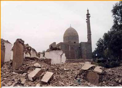
47 Blast Resistance of Steel and Composite Bridges Abolhassan Astaneh-Asl, Ph.D., P.E., Professor Jin Son, Doctoral Graduate Student Marcus Rutner, Ph.D. Post-doctoral Researcher Dept. of Civil and Environmental Engineering University of California, Berkeley Sloboda Bridge in Novi Sad, Serbia and Montenegro
48 Three types of major bridges are studied: 1. Anchored Suspension Bridges 2. Cable-Stayed Bridges 3. Self Anchored Suspension Bridges 1. Suspension Bridge (Anchored) Notice the axial forces in the decks! 2. Cable-Stayed Bridge 3. Self-Anchored Suspension Bridge
 Orthotropic Deck With Axial Force (Self Anchored Suspension")
49 Blast Resistance of Orthotropic Decks in Ground- Anchored and Self-Anchored Suspension Bridges Orthotropic Deck Without Axial Force (Ground-Anchored Suspension Bridges) Orthotropic Deck With Axial Force (Self Anchored Suspension Bridge)


50 Blast Resistance of Steel Bridge Piers and Tower Legs Subjected to Car Bombs Abolhassan Astaneh-Asl, Ph.D., P.E. Professor Dept. of Civil and Environmental Engineering University of California, Berkeley Steel Multi-Cell Damage is Tolerable, Tower Leg Does not Collapse Steel Single Cell Steel Pier Damage is Extensive, Tower Leg Collapses

51 Blast Resistance of Steel Bridge Piers and Tower Legs Subjected to Car Bombs Abolhassan Astaneh-Asl, Ph.D., P.E. Professor Dept. of Civil and Environmental Engineering University of California, Berkeley Composite (Steel+Conc.) Multi-Cell Damage is Tolerable, Tower Leg Does not Collapse Steel Single Cell Steel Pier Damage is Extensive, Tower Leg Collapses
52 Performance of the new 2013 SAS Bay Bridge in the Event of a Blast Attack (Car Bomb) Abolhassan Astaneh-Asl, Ph.D., P.E. Professor Dept. of Civil and Environmental Engineering Before Blast University of California, Berkeley After Blast; Collapses with a small car bomb
53 Performance of the new 19ilever Truss East Spans in the Event of a Blast Attack (Car Bomb) Abolhassan Astaneh-Asl, Ph.D., P.E. Professor Dept. of Civil and Environmental Engineering University of California, Berkeley After Blast; very local damage to member, no collapse

Bridge 3 years in Constructiopn")

 New Tacoma Narrows")
54 Cost and Duration Issues New Self Anchored Bay Bridge 16 years in Construction $6.1 Billion ($19,000/sq ft) Al Zampa (Carquinez )Bridge 3 years in Constructiopn Cost: $220 million ($660/sq ft) Akashi Kaikyo Bridge, Japan 8 years in construction Cost: $4.3 billion ($2900/sq ft) New Tacoma Narrows Bridge 4 years in construction Cost: $900 million $3,000/sq ft)

55 How Did We Get This SAS Bridge? Conflict of Interest in the Engineering Design Advisory Panel Abolhassan Astaneh-Asl, Ph.D., P.E. Professor Dept. of Civil and Environmental Engineering University of California, Berkeley


56 The New SAS Bay Bridge Studies(1997-Present) A. Astaneh, Ph.D., P.E., X. Qian, and M. Tabbakhha, Ph.D. List of Specific Areas of Study in A. Astaneh s SAS Bay Bridge Project: 1. Tower Push-Over 2. Anchor Rods at the Tower Base 3. Tower Out-of-Plumb-ness 4. Welds at the Base of the Tower 5. Welds in the Deck 6. Welded Steel/Concrete Piles 7. Anchorage of Main Cables to the Deck 8. East Pier Shear Key and Bearing Bolts 9. Hot-dip Galvanized A354 BD Bolts 10.East and West End Expansion Joints Structural Seismic Response Simulation Model


57 Pushover Analysis of the New Self-Anchored Suspension Bay Bridge Abolhassan ASTANEH-ASL, Ph.D., P.E., Professor Xin QIAN, Doctoral Graduate Student University of California, Berkeley, USA

58 Problems of the New SAS Bay Bridge Tower Inadequacy Brittle Saddle Connection Brittle Cable Connections Midspan Expansion Joint Expansion Joint at Midspan No Anchors to the Rock Anchor Rod Fractured Weak Pile Concrete Anchor Rods Fractured Cracks in Tower Welds Cracks in Deck Welds Water Inside Deck Corrosion of Cable Anchors

59 Seismic Performance Criteria presented by the Bridge Design Team Functional evaluation earthquake (FEE) The bridge will provide full service almost immediately and there will be minimal damage to the structure. Minimal damage implies essentially elastic performance and is characterized by minor inelastic response, narrow cracking in concrete, no apparent permanent deformations, and damage to expansion joints. Safety evaluation earthquake (SEE) The bridge will provide full service almost immediately and will sustain repairable damage to the structure. Repairable damage is damage that can be repaired with minimum risk of losing functionality; it is characterized by yielding of reinforcement, spalling of concrete cover and limited yielding of structural steel.
60 Pushover Analysis presented by the Bridge Design Team Beam Elements


61 Our Realistic Pushover Analysis Our analysis used inelastic shell elements capable of yielding and local buckling to represent all steel plates in the tower; Vertical stiffeners in the tower shafts were modeled as beam elements.


62 Nonlinear Finite Element Analysis Results
63 Beam vs Shell Discussions

64 Possible Retrofit Discussions
65 Conclusions Use of beam elements in modeling large and complex structures instead of realistic shell elements may result in an incorrect prediction of the behavior of the structure; Local buckling failure mode of the steel plates cannot be captured
66 Conclusions Model using beam elements for the shafts underestimates the stiffness and ultimate strength; This could result in underestimation of the inertia forces generated in the structure during a seismic event as compared to the design analysis results

67 Conclusions The statement that: The shear links between the tower shafts will be the only inelastic elements in the tower and will act as fuses to protect the tower shafts from yielding is inaccurate. Yielding and local buckling of the tower shafts could occur

68 Change of the slope of the tower shafts at about mid-height results in stress concentration and may cause local yielding and local buckling to initiate at that location. Conclusions

69 Since the tower will likely to be pushed beyond the design level earthquake during major earthquakes, it is critical to prevent local buckling of the tower shafts; We propose efficient and economical retrofit measures, as shown on the right, for vertical stiffeners of the tower to prevent local buckling of tower shafts. Conclusions


70 Effect of Fractured Anchor Rods on the Pushover Behavior of the Tower of the New Self-Anchored Suspension Bay Bridge Abolhassan ASTANEH-ASL, Ph.D., P.E., Professor Maryam Tabbakha, Post Doctoral Researcher Xin QIAN, Doctoral Graduate Student University of California at Berkeley, USA
71 Problems of the New SAS Bay Bridge Tower Inadequacy Brittle Saddle Connection Brittle Cable Connections Midspan Expansion Joint Expansion Joint at Midspan No Anchors to the Rock Anchor Rod Fractured Weak Pile Concrete Anchor Rods Fractured Cracks in Tower Welds Cracks in Deck Welds Water Inside Deck Corrosion of Cable Anchors


72 More than 2,200 anchor rods and bolts used in the new SAS Bay Bridge are A354 BD hot-dip galvanized. They are all hydrogen-embrittled In 2013 and 2015 anchor rods started to fracture when tightened


73 The New Self-Anchored Suspension Bay Bridge Elevation of the Main Tower Plan and Elevation of the Pile Cap Footing

74 The New Self-Anchored Suspension Bay Bridge Plan View of the Base Plate and Location of Anchor Rods


75 The New Self-Anchored Suspension Bay Bridge View of the Base Plate and Tower Anchor Rods
76 Objectives As part of the larger project of Seismic evaluation of the new self-anchored bay bridge, the main objective of this work is to To investigate the effect of anchor rod fracture on the pushover behavior of the main tower of the new SAS Bay Bridge To establish the stiffness, strength, buckling behavior, and ductility of the tower when NO anchor rods are connecting the base of the tower to the top of the pile cap.
77 Background In 2013, and a few months before the opening of the bridge, 32 of the 96 anchor rods connecting the seismic shear keys to the top of the Pier E2 on the east end of the SAS Bay Bridge fractured when tightened.
78 Background In 2015, M. Nader, (of the TYLI/Moffitt Joint Venture) the Chief Engineer and Engineer of the Record for the SAS Bay Bridge: Presented analysis of the bridge subjected to a select number of ground motions. He concluded that even without any anchor rods, the response of the bridge to six ground motion records (that the Bridge Design Team has considered in the design of the bridge) will be almost the same as the response with all anchor rods present.

 welds that connect the base of the tower the base")
79 Background A critical review of the validity of this claim as well as the correctness of the analysis is not possible at this time without sufficient information; The bridge model that the Bridge Design Team has used does not seem to include local buckling of the tower shaft plates and fracture of the Partial Joint Penetration (PJP) welds that connect the base of the tower the base plate;


80 Realistic Pushover Analysis Nonlinear Finite Element Analysis Same tower superstructure model

81 Realistic Pushover Analysis Nonlinear Finite Element Analysis Added tower base plate and pile cap model
82 Nonlinear Finite Element Analysis Results Transverse

83 Nonlinear Finite Element Analysis Results Transverse


84 Nonlinear Finite Element Analysis Results Tower Base Response
85 5. Discussions With Anchor Rods versus Without Anchor Rods
86 Lessons Learned As many bridge design codes recommend, the A354 BD high-strength anchor rods should not have been used in this structure in the corrosive environment over the seawater, where the anchor rods are embedded in the pile cap, and pile cap is submerged in seawater.
87 Lessons Learned The A354 BD anchor rods and bolts should not have been hot-dip galvanized. The anchor rods should not have been left at the site in the open for more than three years to be exposed to rain and seawater environment.
88 Lessons Learned The number of threads per inch and the depth of the thread should have been specified correctly to avoid thread stripping under tension The anchor rods should not have been embedded in the concrete of the pile cap;
89 Retrofit Solutions Recommended: The anchor rods need to be replaced. The anchor rods should have a small segment at the top weaker than the main body of the anchor rods to ensure that the small portion at the top acts as a fuse. Instead of usinga354 BD high-strength anchor rods, not allowed to be hot dip galvanized, upset A354 BC anchor rods should have been used.
90 Lessons Learned The A354 BC has a specified minimum yield stress of 99 ksi (683 MPa). The A354 BC bolts can be galvanized either by hot-dip galvanizing, without developing hydrogen embrittlement or could be galvanized mechanically;