STRUCTURAL TECHNICAL REPORT 1
|
|
|
- Eileen Bailey
- 5 years ago
- Views:
Transcription

1 Technical Report 1 Page 1 David Lee AE 481W Structural Option Advisor: Andres Lepage URS Office Building October 5, 2006 STRUCTURAL TECHNICAL REPORT 1 Structural Concepts / Structural Existing Conditions Report

2 Technical Report 1 Page 2 INTRODUCTION This report provides an overview of the structural system which support the URS Office Building located in Columbus, Ohio. The 5 story, 100,000 square foot building is the forerunner in design for the Arena District being developed by Nationwide Realty Investors. The curvature and the setback on the North facade of the building (facing Nationwide Boulevard) along with careful consideration for proportion gives distinction to the otherwise rectangular building. Designed as mercantile/office building, the URS Office Building provides retail area on the first floor and office area from second to fifth floor. Completed construction in January 2001, this design, bid, build project s total cost was $7 million. Figure 1 In the following sections are structural system description, codes applied, frame plan and elevation, design loads, and spot checks. STRUCTURAL SYSTEM URS Office Building is a steel frame structure surrounded by brick masonry veneer along with large punched windows which incorporate industrial glass. Structural steel used for beams, columns, and girders is ASTM A572 grade 50 wide-flange with yield strength of 50,000psi. Longest beam spans 33 4 and longest girder spans 32. Typical bays are 30 x 30 with most bays being approximately a square. The chevron bracings resisting lateral loads are ASTM A500, Grade B tube steel with yield strength of 46,000psi. Spread footings with minimum compressive strength at 28 days of 3000psi together with grade beams are employed as the foundation system. The size of footing varies from 4 x 4 to 14 x 14. The grade beams also vary in width as well as depth. Both the spread footings and grade beams utilize bars #6, #7, #8, or #9 with #4 stirrups. The slab on grade is required minimum compressive strength at 28 days of 4000psi and the composite slabs are to be lightweight concrete with minimum strength of 3000psi. First floor slab
3 Technical Report 1 Page 3 on grade is 5 concrete slab. The composite slabs on floors 2 through 5 are composed of 2 steel deck and 3-1/4 light weight concrete. Steel roof decks are galvanized 20 gage ASTM A653 grade 33 G90 zinc coated steel. The composite steel floor decks are galvanized 20 gage ASTM A653 grade 33 G60 steel. Headed studs ¾ φ x 4 spaced evenly across the steel members are used to achieve composite action. CODES For the URS Office Building structural design was performed under Ohio Basic Building Code 1998 (OBBC). OBBC was created by adopting BOCA National Building Code Structural standards for structural steel, cast in place concrete, pre-cast concrete, metal deck, and masonry are shown below in Table 1. OHIO BASIC BUILDING CODE 1998 STRUCTURAL STEEL AISC Manual of Steel Construction (ASD 91) CAST IN PLACE CONCRETE PRECAST CONCRETE ACI Building Code Requirement for Reinforced Concrete ACI Specification for Structural Concrete for Buildings ACI 318 Building Code Requirement for Reinforced Concrete PCI MNL 120 PCI Design Handbook Pre-cast and Pre-stressed Concrete METAL DECK AISI Specification for the Design of Cold-formed Steel Structural Members SDI Design Manual for Composite Decks, Form Deck, and Roof Decks MASONRY ACI 530.1/ASCE 6/TMS 602 In January 1 of 2002, State of Ohio adopted the 2000 International Building Code (IBC). Current building code in Ohio is the 2005 Ohio Building Code (OBC) based on 2003 IBC. Therefore throughout the report, 2003 IBC along with ASCE 7-05 will be used as the structural standard. Although calculations were performed using ASD 9 th Edition of the steel manual, this report will be determined by LRFD 3 rd Edition of the steel manual. Table 1

4 Technical Report 1 Page 4 FRAME PLAN AND ELEVATION Below in Figure 2 is the largest bay which is 32 x Typical girders are W24 and typical beams are W16. Second to fifth floor has identical framing plan. Roof frame plan varies from floors below, but bay size and location are the unchanged. Figure 2 Three braced frames and moment frames along the perimeter exist to resist the lateral loads for URS Office Building (see Figure 3a and 3c). As shown in Figure 3b the chevron bracing is used for all three frames. The tube steel members which compose the chevron bracing have moment connections. Brace frame 1 (WB-1) resists east/west lateral loads and brace frames 2 and 3 (WB-2 and WB-3) resists north/south lateral loads.

5 Technical Report 1 Page 5 Figure 3a Figure 3b Figure 3c
6 Technical Report 1 Page 6 LOADS Loads are calculated by design parameters given in ASCE 7-05 in conjunction with 2003 IBC. Dead load will be calculated according to the actual weight of the permanent building components. Live load will be directly taken out of 2003 IBC. Snow, wind, seismic calculation will follow ASCE 7-05 procedures. Gravity Load Dead Loads (PSF) actual weight of the permanent building components Structural Steel PSF Metal Deck PSF Concrete PSF MEP PSF Partition PSF Total Dead Load PSF Live Loads (PSF) from 2003 IBC: Table Roof Snow PSF Office Floor PSF Corridor PSF Lobby PSF Retail PSF Penthouse Floor PSF Mechanical Unit PSF + weight of equipment Snow Load (PSF) from ASCE 7-05: Chapter 5 Primary concern for snow load is next to the penthouse where drifting may occur. Following the guidelines in ASCE 7-05 snow load was calculated and drift was considered. The maximum drift calculated was 59.3 PSF

7 Technical Report 1 Page 7 Lateral Load Wind from ASCE 7-05: Chapter 6 Height Above Windward plus Ground (ft) Leeward Pressure PSF PSF PSF PSF PSF PSF PSF PSF PSF

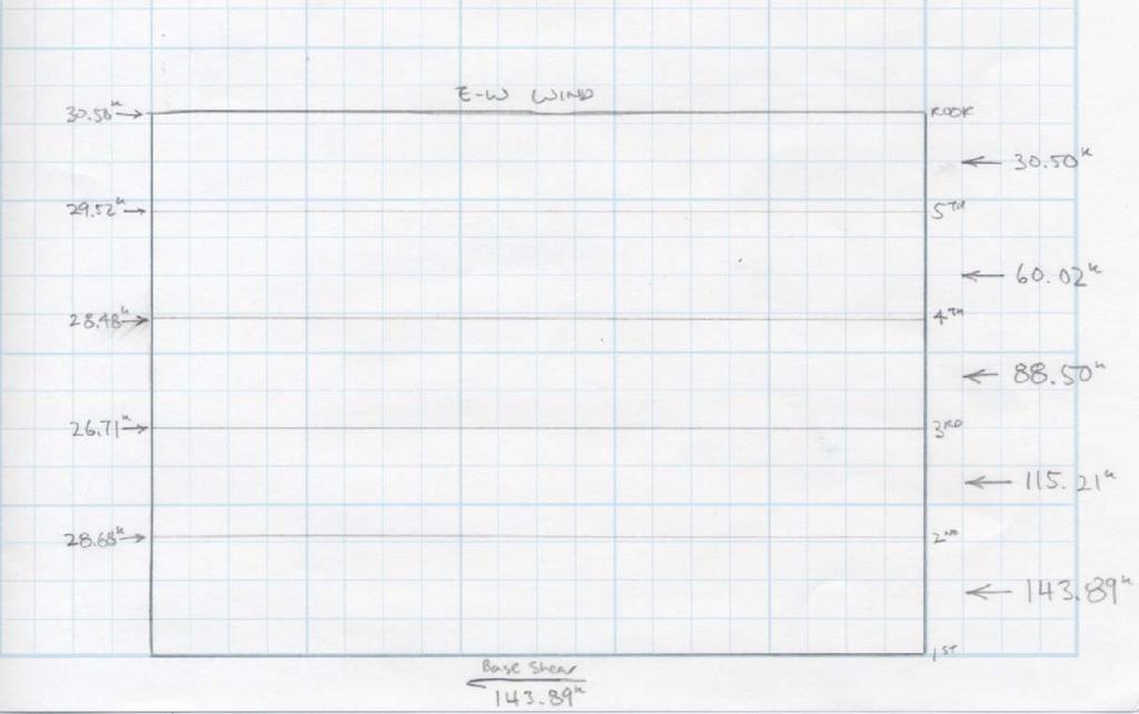
8 Technical Report 1 Page 8


9 Technical Report 1 Page 9 Seismic from ASCE 7-05: Chapter 11
10 Technical Report 1 Page 10 SPOT CHECKS Beams To spot check the beams, a typical bay on the second floor was checked. RAM model showed the beams were adequate for the load provided in this report. Also hand calculation was performed which shows adequacy of the beam used. Girders A girder was taken from the same bay as the beam above. Again Ram model as well as the hand calculations agreed with the construction documents. Columns An interior column was taken from the first floor for spot check. The column listed on the column schedule was adequate in holding the loads provided in this report. RAM analysis was performed along with quick hand checks. Bracing Total factored load were taken into account for the bracing member calculations. Since dead, live, and wind load combination controlled in North-South lateral load, the loads were factored and applied to bracing two and three. Bracing one was checked against dead, live, and seismic combination loads which controlled East-West lateral load. Bracing members were assumed to take 80% of the lateral loads and moment frames were assumed to resist the rest. Bracing members along with moment frames were adequate to provide lateral resistance.

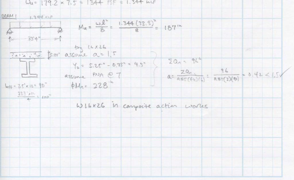
11 Technical Report 1 Page 11 CALCULATIONS Beam


12 Technical Report 1 Page 12 Girder


13 Technical Report 1 Page 13 Column


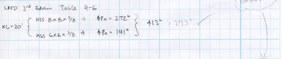
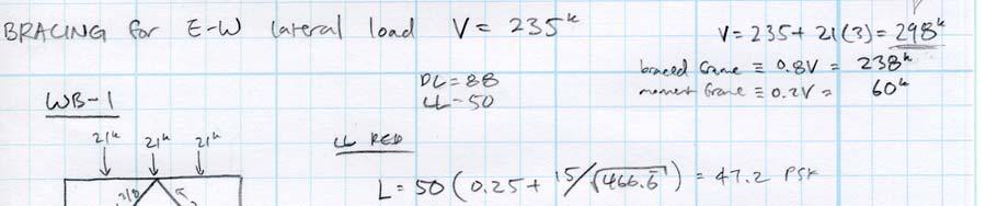
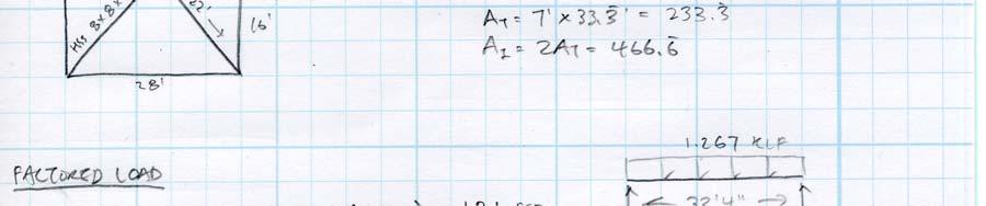
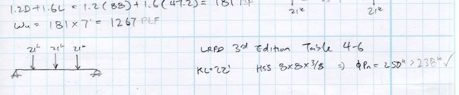
14 Technical Report 1 Page 14 Bracing
15 Technical Report 1 Page 15 Snow Load Calculation Ground Snow Load (p g ) = 20.0 psf (Fig p ) Bldg. Classification Category = III (Table p. 16-5) Snow Importance Factor ( I S ) = 1.1 (Table p. 16-5) Snow Exposure Factor (C e ) = 1.0 (Table p ) Snow Thermal Factor (C t ) = 1.0 (Table p ) Min Flat Roof Snow Load = 22.0 psf (ASCE 7 Section 7.3) Flat Roof Snow Load ASCE 7 Eq 7-1 (p f ) = 15.4 psf (ASCE 7 Section 7.3) Rain-on-snow Surcharge Load = 20.4 psf (ASCE 7 Section 7.10) Flat Roof Snow Load Used (p f ) = 22.0 psf Roof Slope Factor Unobstructed & Slippery (C S ) = 1.00 (ASCE 7 Fig 7-2 p. 84) Roof Slope Factor All Others (C S ) = 1.00 (ASCE 7 Fig 7-2 p. 84) Sloped Roof Snow Load Unobstruct. & Slippery (P S ) = Sloped Roof Snow Load All Others (P S ) = 22.0 psf 22.0 psf Sloped Roof Snow Load Used (P S ) = 22.0 psf Snow Density (γ) = 16.6 pcf (ASCE 7 Eq 7-4 p. 79) Length of Length of Drift P at Edge Upper Lower Δ Roof P Width W d P max (psf) min = P f Location of Roof Roof, l u Roof, l u Height (ft) (psf) (ft) (psf) (ft) (ft) Intermed. R Wind Load Calculation (North South) Input Parameters: Basic Wind Speed (V, mph) = 80 Building Length (L, ft) = (Parallel to Wind) Exposure Category = B Building Width (B, ft) = Bldg. Classification Category = III (Normal to Wind) Wind Importance Factor (I W ) = 1.15 Roof Slope (θ, deg.) = 0 in per foot (Degrees from Horz.) 0.00 deg. from horiz. Mean Building Height (h, ft) = Internal Pressure Coef (GC pi ) = 0.18 (Pressure) Multipilers to obtain K1 = (Suction) Topographic factor: K2 = 1 K3 = 1 Topographic Factor (K zt )= 1 Wind Directionality Factor (K d )= 0.85 Calculated Parameters: Velocity Press. Exposure Coef at h (K h )= 0.92 h/l = Velocity Pressure at h (q h ) = psf L/B = Gust Effect Factor (G) = h/b = Internal Pressure (q h GC pi ) = 2.7 psf α = psf z g = 1200
 Exposure Category = B Building Width (B, ft) = 114.67 Bldg. Classification Category = III (Normal to Wind) Wind Importance Factor (I W ) = 1.15 Roof Slope (θ, deg.")
 Topographic factor: K2 = 1 K3 = 1 Topographic Factor (K zt )= 1 Wind Directionality Factor (K d )= 0.85 Calculated Parameters: Velocity Press. Exposure Coef at h (K h )= 0.92 h/l = 0.")
16 Technical Report 1 Page 16 Wind Load Calculation (East West) Input Parameters: Basic Wind Speed (V, mph) = 80 Building Length (L, ft) = (Parallel to Wind) Exposure Category = B Building Width (B, ft) = Bldg. Classification Category = III (Normal to Wind) Wind Importance Factor (I W ) = 1.15 Roof Slope (θ, deg.) = 0 in per foot (Degrees from Horz.) 0.00 deg. from horiz. Mean Building Height (h, ft) = Internal Pressure Coef (GC pi ) = 0.18 (Pressure) Multipilers to obtain K1 = (Suction) Topographic factor: K2 = 1 K3 = 1 Topographic Factor (K zt )= 1 Wind Directionality Factor (K d )= 0.85 Calculated Parameters: Velocity Press. Exposure Coef at h (K h )= 0.92 h/l = Velocity Pressure at h (q h ) = psf L/B = Gust Effect Factor (G) = h/b = Internal Pressure (q h GC pi ) = 2.7 psf α = psf z g = 1200
: 1 Response Modification Factor (R) = 3.")
17 Technical Report 1 Page 17 Seismic Calculations Input Parameters: Building Height (h n, feet) = Max. Considered Earthquake (MCE) Short Period (S S ) = 12.0% MCE 1 sec. Period (S 1 ) = 4.6% Site Soil Class = D Bldg. Classification Category = II Seismic Use Group = I Seismic Occupancy Importance Factor (I E ): 1 Response Modification Factor (R) = 3.25 Deflection Amplification Factor (C d ) = 4.5 C T = 0.02 x= 0.75 Period Calculated from Analysis (T, sec.) = 0.84