Advanced FBC: Significant Changes to the 5 th Edition (2014) Florida Building Code, Building and Residential. presented by
|
|
|
- Magnus Ryan
- 5 years ago
- Views:
Transcription
1 Advanced FBC: Significant Changes to the 5 th Edition (2014) Florida Building Code, Building and Residential presented by T. Eric Stafford T. Eric Stafford & Associates, LLC This material is protected and the property of T. Eric Stafford & Associates, LLC and cannot be reproduced or used without the express written permission of T. Eric Stafford & Associates, LLC. 1 FBC 5 th Edition (2014) Glitch Amendments to be incorporated in First Printing of Codes Codes available 2015 Effective Date June 30,
2 General All Florida-specific amendments sunset after each code cycle Have to be resubmitted each cycle Seismic and snow criteria remain in the code Does not apply in Florida May be somewhat confusing in the FBCR 3 FBC, Building 5 th Edition (2014) Scope. The provisions of this code shall apply to the construction, alteration, relocation, enlargement, replacement, repair, equipment, use and occupancy, location, maintenance, removal and demolition of every building or structure or any appurtenances connected or attached to such buildings or structures. 4 2
3 FBC, Building 5 th Edition (2014) Exceptions: 1. Detached one- and two-family dwellings and multiple single-family dwellings (town houses) not more than three stories above grade plane in height with a separate means of egress and their accessory structures shall comply with the Florida Building Code, Residential. 2. Existing buildings undergoing repair, alterations or additions and change of occupancy shall comply with Chapter 34 of this code. 5 Administration Referenced codes and standards. The codes and standards referenced in this code shall be considered part of the requirements of this code to the prescribed extent of each such reference and as further regulated in Sections and Conflicts. Where differences conflicts occur between provisions of this code and referenced codes and standards, the provisions of this code shall apply. 6 3
4 Administration Provisions in referenced codes and standards. Where the extent of the reference to a referenced code or standard includes subject matter that is within the scope of this code or the International Codes listed in Section 101.4, the provisions of this code or the International Codes listed in Section 101.4, as applicable, shall take precedence over the provisions in the referenced code or standard. 7 Occupancy Classification Restaurants and drinking establishments with an occupant load of less than 50 persons shall be classified as Group M, mercantile Small buildings and tenant spaces. A building or tenant space used for assembly purposes with an occupant load of less than 50 persons shall be classified as a Group B occupancy. 8 4
5 Occupancy Classification Small assembly spaces. The following rooms and spaces shall not be classified as Assembly occupancies: 1. A room or space used for assembly purposes with an occupant load of less than 50 persons and accessory to another occupancy shall be classified as a Group B occupancy or as part of that occupancy. 2. (no changed) 9 Occupancy Classification Assembly Group A-2. Assembly uses intended for food and/or drink consumption including, but not limited to: Banquet halls Casinos (gaming areas) Nightclubs Restaurants, cafeterias and similar dining facilities (including associated commercial kitchens) Taverns and bars 10 5
6 Basements Basements. A basement of a building shall not count as a story when applying Table 503 for allowable building height. 11 Basements BASEMENT. A story that is not a story above grade plane (see Story above grade plane ). This definition of Basement does not apply to the provisions of Section 1612 for flood loads. 12 6
7 Basements STORY ABOVE GRADE PLANE. Any story having its finished floor surface entirely above grade plane, or in which the finished surface of the floor next above is: 1. More than 6 feet (1829 mm) above grade plane; or 2. More than 12 feet (3658 mm) above the finished ground level at any point 13 Allowable Area Increase Frontage increase. Every building shall adjoin or have access to a public way to receive a building area increase for frontage. Where a building has more than 25 percent of its perimeter on a public way or open space having a width of not less than 20 feet (6096 mm), the frontage increase shall be determined in accordance with Equation 5-2: I f = [F / P ]W / 30 where: I f = Area increase due to frontage. F = Building perimeter that fronts on a public way or open space having 20 feet (6096 mm) open minimum width (feet). P = Perimeter of entire building (feet). W = Width of public way or open space (feet) in accordance with Section
8 Allowable Area Increase Width limits. To apply this section W shall be measured perpendicular from the face of the building to the closest interior lot line. Where the building fronts on a public way, the entire width of the public way shall be used. Where two 15 Allowable Area Increase Weighted average W = (L 1 x w 1 + L 2 x w 2 + L 3 x w 3 ) / F. (Equation 5-3) where: L n = Length of a portion of the exterior perimeter wall. w n = Width of open space associated with that portion of the exterior perimeter wall. F = Building perimeter that fronts on a public way or open space having a width of 20 feet (6096 mm) or more. 16 8
9 17 Allowable Area Increase Weighted Average W = [(20 ft x 100 ft) + (30 ft x 200 ft) + (20 ft x 100 ft)]/400 ft = 25 ft 18 9
10 Fire-Resistance Req. for Building Elements Table 601 Fire-Resistance Rating Requirements for Building Elements (excerpt) Building Element Type I Bearing Walls A B Exterior Walls Interior Walls Projections Projections. Cornices, eave overhangs, exterior balconies and similar projections extending beyond the exterior wall shall conform to the requirements of this section and Section Exterior egress balconies and exterior exit stairways and ramps shall also comply with Sections 1019 and 1026, respectively. Projections shall not extend beyond the distance determined by the following three methods whichever results in the lesser projection: any closer to the line used to determine the fire separation distance than shown in Table
11 Projections Table Minimum Distance of Projection FIRE SEPARATION DISTANCE (FSD) MINIMUM DISTANCE FROM LINE USED TO DETERMINE FSD 0 feet to less than 2 feet Projections not permitted 2 feet to less than 5 feet 24 inches 5 feet or greater 40 inches 21 Projections 22 11
12 Projections 23 Projections 24 12
13 Fire Wall Extensions Roof Vertical continuity. Fire walls shall extend from the foundation to a termination point at least 30 inches above both adjacent roofs. Exceptions: 1-5. (No changes) 6. Buildings with sloped roofs in accordance with Section Fire Wall Extensions Roof Buildings with sloped roofs. Fire wall serves as interior wall Roof on one or both sides slopes to fire wall at greater than 2:12 Fire wall has to extend to a height equal to height of roof located 4 feet from the fire wall plus 30 inches Extension to be at least 30 inches for all cases 26 13
14 Fire Wall Extensions Roof 27 Fire Partitions General. The following wall assemblies shall comply with this section. 1. Walls separating dwelling units in the same building as required by Section Walls separating sleeping units in the same building as required by Section Walls separating tenant spaces in covered and open mall buildings as required by Section Corridor walls as required by Section Elevator lobby separation as required by Section Walls separating individual tenant spaces
15 Fire Partitions Exceptions: 1. In Group B and S occupancies, walls used to separate tenants shall not be required to have a fire-resistance rating, provided no area between fire partitions having a 1-hour fire-resistance rating exceeds 3,000 square feet (279 m2). 2. In aircraft hangar occupancies, walls used to separate tenants shall not be required to have a fire-resistance rating, provided the aircraft hanger is constructed in accordance with the requirements of Section In mini-warehouses/self-storage buildings, walls used to separate tenants shall not be required to have fire-resistance rating, provided a sprinkler system meeting the requirements of Ordinary Hazard Group II as defined by NFPA 13, is installed employing quick response heads. 29 Horizontal Assemblies Fire-resistance rating. The fire-resistance rating of floor and roof assemblies shall not be less than that required of not less than that required by Section Horizontal assemblies separating dwelling units in the same building and horizontal assemblies separating sleeping units in the same building and floor assemblies separating individual tenant spaces in the same building in all other occupancies shall be a minimum of 1-hour fireresistance-rated construction
16 Minimum Required Egress Width 2010 FBCB 0.3 inch x occupant load for stairways 0.2 inch x occupant load for other egress 2013 FBCB 0.3 inch x occupant load for stairways 0.2 inch x occupant load for stairways in sprinklered buildings with emerg. voice/alarm systems 0.2 inch x occupant load for other egress 0.15 inch x occupant load for other egress sprinklered buildings with emerg. voice/alarm systems 31 Minimum Required Egress Width Assume an Exit is serving 300 occupants Component Sprinklered building with emerg. voice/alarm system Minimum Width Without sprinklers or emerg. voice/alarm system Door 45 inches 50 inches Stairway 60 inches 90 inches Corridor 45 inches 50 inches 32 16
17 Stairways General. Stairways serving occupied portions of a building shall comply with the requirements of this section. 33 Interior Stairs and Ramps Complete revision of provisions for interior exit stairways and ramps Changes to basic means of egress terminology Generally a clarification Intended to clarify confusing interpretations 34 17
18 Interior Stairs and Ramps Exit access stairway. An interior stairway that is not a required interior exit stairway. Interior exit stairway. An exit component that serves to met one or more means of egress design requirements, such as required number of exits or exit access travel distance, and provides for a protected path of egress travel to the exit discharge or public way. 35 Interior Stairs and Ramps All stairs in a building are elements of the required means of egress and must comply with Chapter 10. Unenclosed stairways are not considered an exit To qualify as exits, all exit stairway must be enclosed with fire-resistance rating Stairways permitted to be open, are exit access stairway may be open or enclosed as code allows Exit access travel distance is measured from an entrance to an exit, and includes the travel distance on an exit access stairway 36 18

19 Floor-level Exit Signs Floor-Level Exit Signs in Group R-1. Required in Group R-1 where exit signs are required Required in all areas serving guest rooms Corridors Stairwells Other egress components
20 Floor-level Exit Signs Location Bottom of sign between 10 and 12 inches above floor level Flush mounted to door or wall When mounted on the wall, the edge of sign has to be within 4 inches of the door frame on the latch side. 39 Handrail Height Handrail height can exceed the maximum height for continuous transitions between flights In Group R-3 and dwelling units in Group R-2 for transitions at winder treads, from handrail to guard, or at start of a flight
21 Handrail Height Height. Handrail height, measured above stair tread nosings, or finish surface of ramp slope, shall be uniform, not less than 34 inches (864 mm) and not more than 38 inches (965 mm). Handrail height of alternating tread devices and ship ladders, measured above tread nosings, shall be uniform, not less than 30 inches (762 mm) and not more than 34 inches (864 mm). Exceptions: Handrails for stairs not required to be accessible that form part of a guardrail may be 42 inches (1067 mm) high. 41 Handrail Height 1. When handrail fittings or bendings are used to provide continuous transition between flights, the fittings or bendings shall be permitted to exceed the maximum height. 2. In Group R-3 occupancies; within dwelling units in Group R-2 occupancies; and in Group U occupancies that are associated with a Group R-3 occupancy or associated with individual dwelling units in Group R-2 occupancies; when handrail fittings or bendings are used to provide continuous transition between flights, transition at winder treads, transition from handrail to guard, or when used at the start of a flight, the handrail height at the fittings or bendings shall be permitted to exceed the maximum height
 and not greater than 61/4 inches (160 mm) with a maximum cross-sectional dimension of 21/4 inches")
22 Handrail Height 43 Handrail Graspability Type I. Handrails with a circular cross section shall have an outside diameter of at least 11/4 inches (32 mm) and not greater than 2 inches (51 mm). Where the handrail is not circular, it shall have a perimeter dimension of at least 4 inches (102 mm) and not greater than 61/4 inches (160 mm) with a maximum cross-sectional dimension of 21/4 inches (57 mm) and minimum cross-sectional dimension of 1 inch (25 mm). Edges shall have a minimum radius of 0.01 inch (0.25 mm)
23 Handrail Graspability 45 Guards at Windows Window sills. In Occupancy Groups R-2 and R-3, one- and two-family and multiple-family dwellings, where the opening of the sill portion of an operable window is located more than 72 inches (1829 mm) above the finished grade or other surface below, the lowest part of the clear opening of the window shall be at a height not less than inches (915 mm) above the finished floor surface of the room in which the window is located. Operable sections of windows shall not permit openings that allow passage of a 4-inch-diameter (102 mm) sphere where such openings are located within 36 inches (915 mm) of the finished floor
24 Guards at Windows 47 Guard Height For R-3 and dwellings units in R-2 not more than 3 stories above grade in height with separate means of egress, guards permitted to be not less than 36 inches high above walking surface
25 Guard Height Height. Required guards shall not be less than 42 inches (1067 mm) high, measured vertically above the as follows: 1. From the adjacent walking surfaces; adjacent fixed seating or 2. On stairs, from the line connecting the leading edges of the treads nosings; and 3. On ramps, from the ramp surface at the guard. 49 Guard Height Exceptions: 1. For occupancies in Group R-3 not more than three stories above grade in height and within individual dwelling units in occupancies in Group R-2 not more than three stories above grade in height with separate means of egress, required guards shall not be less than 36 inches (914 mm) in height measured vertically above the adjacent walking surfaces or adjacent fixed seating (no change) 50 25
26 Structural Changes Minor changes to structural requirements Wind Loads still based on ASCE High-Velocity Hurricane Zones Many of the HVHZ sections rolled into the general parts of the code. HVHZ for Chapter 14 deleted HVHZ for Chapter 18 deleted HVHZ for Chapter 19 deleted HVHZ for Chapter 25 deleted 52 26
27 High-Velocity Hurricane Zones Even sections that remain have been significantly reduced based on: If the provision is covered adequately in the base code If the provision is not related to structural wind resistance design 53 Roofing New underlayment requirements Consistent with reroofing requirements Nearly all Chapter 15 Florida-specific amendments from the 2010 code have been carried forward in the 2013 FBCB 54 27
28 Roofing - Underlayment New underlayment requirements apply to Asphalt shingles Clay and concrete tile Metal roof panels Metal roof shingles Mineral-surfaced roll roofing Slate shingles Wood shakes and shingles. 55 Underlayment Asphalt Shingles 2:12 Slope < 4:12 ASTM D 226 Type I or II ASTM D 4869 Type II or IV ASTM D layer system (19 in. overlap) 1 inch caps 1 row in field at 12 in. o.c. 6 in. o.c. at overlaps 56 28
29 Underlayment Asphalt Shingles Slope 4:12 ASTM D 226 Type II ASTM D 4869 Type IV ASTM D layer system (2 inch overlap) 1 inch caps 1 row in field at 12 in. o.c. 6 in. o.c. at overlaps 57 Underlayment Asphalt Shingles Synthetic underlayment permitted fastened in accordance with this section and manufacturer s recommendations ASTM D 1970 underlayment permitted over the entire roof deck 58 29
30 Underlayment Other roof coverings 2 layer system with ASTM D 226 Type I or II, ASTM D 4869 Type II or IV, or ASTM D 6757 permitted for any slope 1 layer system with ASTM D 226 Type II, ASTM D 4869 Type IV, or ASTM D 6757 permitted for any slope Synthetic underlayment permitted ASTM D 1970 underlayment permitted, Except for Wood Shingles and Shakes 59 Photovoltaic Systems Photovoltaic shingles/modules still required to meet ASTM D 3161 or TAS 107. Rooftop-mounted systems to be designed for component and cladding loads using effective wind area based on the dimensions of a single unit frame
31 Photovoltaic Systems Photovoltaic Systems. Rooftop-mounted photovoltaic systems shall be designed for wind loads for component and cladding loads in accordance with Chapter 16 using an effective wind area based on the dimensions of a single frame. 61 Wind Loads Minor changes to wind design criteria ASCE 7-10 referenced for wind loads Strength design-level (ultimate) maps remain in the code unchanged from the 2010 FBCB 62 31
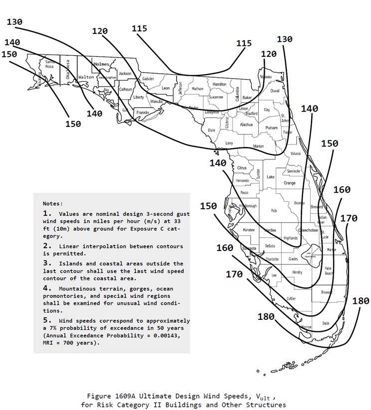
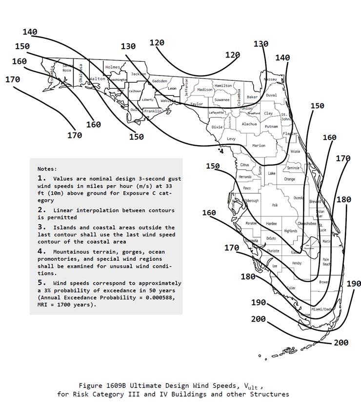
32 ASCE 7-10 Review Basic Wind Speeds 3 new maps Risk Category II (700 year return period) Risk category III and IV (1700 year return period) Risk Category I (300 year return period) Strength design-based or Ultimate wind speeds Risk Category replaces the term Occupancy Category 63 ASCE 7-10 Review Basic Wind Speeds Strength Design Load Factor = 1.0 Allowable Stress Design multiply W x 0.6 Use of different maps for different Risk Categories negates the need for Importance Factors I deleted from wind chapters 64 32
33

34 67 FBC, Building 5 th Edition Review Wind Speed, V ult. Ultimate design wind speeds. Wind Speed, V asd. Nominal design wind speeds
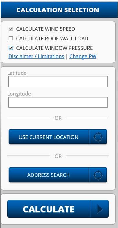
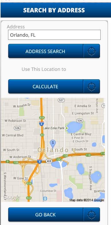
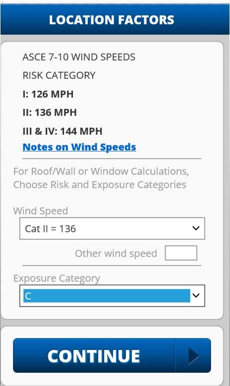
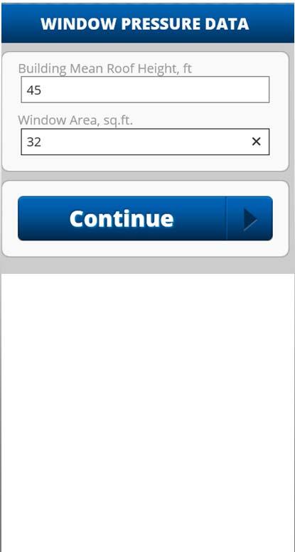
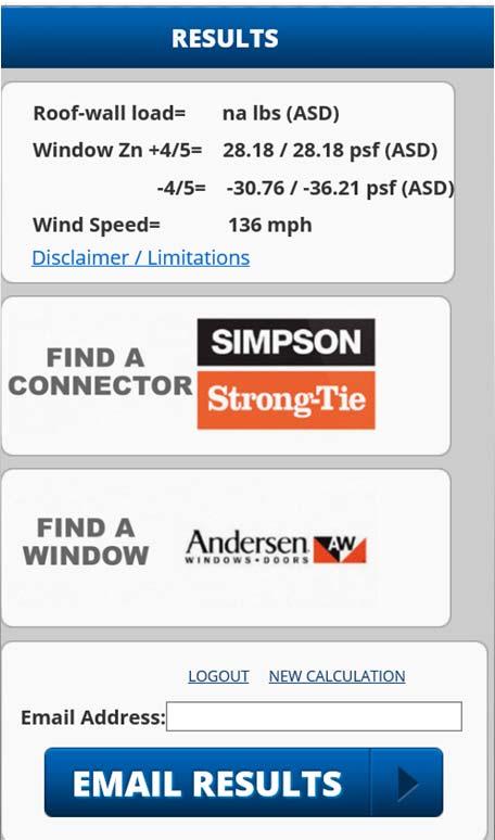
35 Wind Loads Wind speeds New wind speed app Site-specific wind speeds Roof-to-wall loads Window design pressures. 69 Web App Example Office building Orlando, FL Large open area at site, Exp C MRH is 45 feet Window size = 32 square feet Find required DP using ASCE 7-10 and 2010 FBCR Window in corner zone 70 35

36

37
38
39 FBC, Building 5 th Edition Review Section Converting from V ult to V asd V asd = V ult 0.6 Where: V asd = allowable stress design wind speed applicable to methods specified in Exceptions 1 through 5 of Section V ult = strength design wind speeds determined from Figures 1609A, 1609B, or 1609C. 77 FBC, Building 5 th Edition Review Testing to allowable or nominal loads Where testing for wind load resistance is based on allowable or nominal wind loads, the design wind loads determined in accordance with ASCE 7 or Section 1609 of the Florida Building Code, Building are permitted to be multiplied by 0.6 for the purposes of the wind load resistance testing. Applicable to ASTM E 330 for doors AAMA/WDMA 101 standards for glass windows and doors 78 39
40 FBC, Residential 5 th Edition R101.2 Scope. The provisions of the Florida Building Code, Residential, shall apply to the construction, alteration, movement, enlargement, replacement, repair, equipment, use and occupancy, location, removal and demolition of detached one and two family dwellings and (townhouses) not more than three stories above grade plane in height with a separate means of egress and their accessory structures. 79 FBC, Residential 5 th Edition Exceptions: 1. No significant change 2. Owner-occupied lodging houses with five or fewer guestrooms shall be permitted to be constructed in accordance with the Florida Building Code, Residential when equipped with a fire sprinkler system in accordance with Section P No change
41 FBC, Residential 5 th Edition GUESTROOM. Any room or rooms used or intended to be used by one or more guests for living or sleeping purposes. LODGING HOUSE. A one-family dwelling where one or more occupants are primarily permanent in nature, and rent is paid for guestrooms. 81 Wind Loads Minor changes to wind design criteria ASCE 7-10 referenced for wind loads Strength design-level (ultimate) maps remain in the code unchanged from the 2010 FBCB 82 41
42 Wind Loads R Wind limitations and wind design required. The wind provisions of this code shall not apply to the design of buildings where the ultimate design wind speed, V ult, from Figure R301.2(4) equals or exceeds 115 miles per hour (51 m/s). 83 Wind Loads In regions where the basic ultimate design wind speed, V ult, shown on Figure R301.2(4) equals or exceeds 115 miles per hour (51 m/s), the design of buildings for wind loads shall be in accordance with one or more of the following methods: 84 42
43 Wind Loads AF&PA WFCM Now updated to ultimate wind speeds Wind speed conversion not required ICC 600 ASCE 7-10 AISI S230 (Steel framing) Concrete masonry in accordance with the code MAF Guide 85 Exterior Walls R302.1 Exterior walls. Construction, projections, openings and penetrations of exterior walls of dwellings and accessory buildings shall comply with Table R302.1(1); or dwellings equipped throughout with an automatic sprinkler system installed in accordance with Section P2904 shall comply with Table R302.1(2)


44 Exterior Walls 87 Exterior Walls 88 44
45 Exterior Walls 2010 FBCR Walls Projections Openings in walls Penetrations EXTERIOR WALL ELEMENT (Fire-Resistance Rated) ( Not Fire-Resistance Rated) (Fire-Resistance Rated) Not (Fire-Resistance Rated) Not Allowed MINIMUM FIRE-RESISTANCE RATING 1 hour-tested in accordance with ASTM E 119 or UL 263 with exposure form both sides 0 Hours 1 hour on the underside 0 Hours N/A MINIMUM FIRE SEPARATION DISTANCE 0 feet 3 feet 2 feet 3 feet N/A 25% Maximum Wall Area 0 Hours 3 feet Unlimited 0 Hours 3 feet Comply with Section R317.3 All <3 feet T. Eric Stafford & Associates, None LLC Required 3 feet 89 Garage Opening Protections R Opening protection. Openings from a private garage directly into a room used for sleeping purposes shall not be permitted. Other openings between the garage and residence shall be equipped with solid wood doors not less than 13/8 inches (35 mm) in thickness, solid or honeycomb-core steel doors not less than 13/8 inches (35 mm) thick, or 20-minute fire-rated doors, equipped with a self-closing device
46 Landings at Doors Entire section reformatted. Significant technical changes A landing is required at the required egress door regardless of the number of stairway risers 2010 FBCR does not require a landing at the required egress door where a stairway of two or fewer risers is located on the exterior side of the door 91 Landings at Doors (cont.) The door can swing over the landing under any circumstances 2010 FBCR permits the floor or landing to be 7 ¾ in. below the top of the threshold provided door does not swing over the landing or floor FBCR permits the door to be outswinging in all cases 92 46
47 Landing at Required Egress Door 93 Smoke Alarms Wireless smoke alarms allowed for interconnection in lieu of a physical connection Applies to new and existing construction 94 47
48 Smoke Alarms R314.5 Interconnection. Where more than one smoke alarm is required to be installed within an individual dwelling unit in accordance with Section R314.3, the alarm devices shall be interconnected in such a manner that the actuation of one alarm will activate all of the alarms in the individual unit. Physical interconnection of smoke alarms shall not be required where listed wireless alarms are installed and all alarms sound upon activation of one alarm. 95 Floor Fire Protection Floor assemblies required to have a minimum ½ in. gypsum wallboard, or 5/8 in. wood structural panel, or equivalent on the underside of the floor framing members Applies to basements and garages where there is a floor above 96 48
49 Floor Fire Protection Exceptions: Floor assemblies located over sprinklered spaces Floor assemblies over crawl spaces not intended for storage of fuel-fired appliances Small areas (80 sq ft) with blocking at the perimeter 2 x 10 in. or greater dimensional lumber 97 Vinyl Siding New restrictions on vinyl siding applied over foam plastic sheathing 115 mph V ult <130 mph Same as 2010 FBCR With gypsum board on inside multiply Vinyl Siding Design Pressure Rating by 0.39 Without gypsum board multiply Vinyl Siding Design Pressure Rating by mph V ult < 130 mph Multiply Vinyl Siding Design Pressure Rating by

50 Vinyl Siding V ult 140 mph Foam sheathing has to be installed over a material capable of separately resisting 100% of the design wind load 99 Vinyl Siding
51 The End T. Eric Stafford, P.E. 205/