PAT Construction Technology of High rise Building. Lateral System: Steel Building
|
|
|
- Charlene Cook
- 5 years ago
- Views:
Transcription
1 PAT Construction Technology of High rise Building Lateral System: Steel Building
2 Topic Learning Outcome UNDERSTAND the lateral systems for steel buildings. IDENTIFY the structural form/system including semirigid frames, rigid frames, braced frames, staggered truss system, eccentric bracing systems, interacting system of braced and rigid frames, outrigger and framed tube system.
3 Structural Form Which structural system is the most economical for the building? (steel used, fabrication and erection costs) The structural form of tall buildings concerned mainly the arrangement of primary vertical components and their interconnection. Floor systems play an integral part with the vertical components in resisting the lateral as well as the gravity loading.
4 Structural Form Major characteristics: the need to resist lateral forces due to wind or earthquake, must prevent excessive deflections and must help to provide stability.
5 Structural Form Various types of structural form are as follows: 1. Semi-rigid frames 2. Rigid-frames 3. Braced frames 4. Rigid frame and braced frame interaction 5. Framed-tube structures 6. Outrigger-braced structures 7. Suspended structures 8. Core structures 9. Space structures 10. Hybrid structures
6 1. Semirigid frames Semirigid frames are those connections whose behavior is intermediate between fully rigid and simple connections. Such connections offer substantial restraint to the end moment and can effect sufficient reduction in the midspan moment of a gravity-loaded beam. However, they are not rigid enough to prevent all the rotation of the end of the beam. Rarely been used - difficulty of obtaining a reliable analytical model to predict the complex connections.
7 1. Semirigid frames Connections in simple frames are designed to transfer vertical shear only, assuming that there is no bending moment present at the connection. Connection in fully rigid frames are called upon to develop full resistance to both shear and bending moment and are assumed to have sufficient rigidity to hold the original angles between connecting members. Semirigid frames are those whose connection behavior is intermediate between simple and fully rigid connection.
8 1. Semirigid frames
9 1. Semirigid frames Although the reduction in the midspan moment of a beam is permitted with semirigid connections, in practice this procedure has not found wide acceptance primarily because of lack of reliable analytical techniques.
10 Disadvantages: Straightforward application of this method in structures can results in: Structures with overstressed column Structures that exhibit sway deflections much in excess of calculated values
11 2. Rigid-Frame Structure Rigid connections with sufficient stiffness to hold the angles between members virtually unchanged under load. Consist of rectangular grid of horizontal beams and vertical columns connected in the same plane by means of rigid joints. The frame may be in plane of an interior wall of the building or in the plane of the exterior face of the building. Because of the continuity of members at the joints, the rigid frame responds to lateral loads primarily through flexure of beams and columns.
12 2. Rigid-Frame Structure
13 2. Rigid-Frame Structure Advantages: 1. Its open rectangular arrangement which allows freedom of planning and easy fitting of doors and windows. 2. Economy for buildings up to about 25 stories. 3. Ideally suited for reinforced concrete buildings because of the inherent rigidity of reinforced concrete joint. 4. Gravity loading also is resisted by the rigid-frame action. Negative moment are induced in the girders adjacent to the column causing the mid-span positive moment to be significantly less than in a simply supported span.
14 2. Rigid-Frame Structure Disadvantages: 1. Above 25 stories the relatively high lateral flexibility of the frame calls for uneconomically large member in order to control the drift. 2. For steel framing buildings, the moment resistant connections in steel tend to be costly. 3. The sizes of the columns and girders of a rigid frame are directly influenced by the magnitude of the external shear at that level, therefore the sizes increase toward the base. Consequently, the design of the floor framing cannot be repetitive. 4. Sometimes it is not possible in the lowest stories to accommodate the required depth of girder within the normal ceiling space. 5. In structure in which gravity loads dictate the design, economies in member sizes that arise from this effect tend to be offset by the higher cost of the rigid joints.

15 3. Braced-Frame Structures
16 3. Braced-Frame Structures Attempts to improve upon the efficiency of pure rigid frame by virtually eliminating the column and girder bending factors. This is achieved by adding truss members such as diagonals between the floor systems. The shear is now primarily absorbed by the diagonals and not by the girders. The diagonals carry the lateral forces directly in predominantly axial action, providing for nearly pure cantilever behavior.
17 3. Braced-Frame Structures Lateral resistance of the structure is provided by diagonal member that together with the girder form web of the vertical truss with the columns acting as the chords.
18 3. Braced-Frame Structures Bracing is generally regarded as an exclusively steel system because the diagonals are inevitably subjected to tension for one or the other directions of lateral loading. Concrete bracing of the double diagonal form is sometimes used with each diagonal designed as a compression member to carry the full external shear.
19 3. Braced-Frame Structures (a) Diagonal bracing in two-story increments (b) K-braced frame (c) K-braced frame (d) Bracing for a three-bay frame
20 3. Braced-Frame Structures Advantages: 1. Bracing able to produce a laterally very stiff structure for a minimum of additional material, make it an economical structural form for any height of building. 2. Advantage of fully triangulated bracing is that girders usually participated only minimum in the lateral bracing action; consequently, the floor framing design is independent of its level in the structure. Therefore, can be repetitive up the height of the building with obvious economy in design and fabrication.
21 3. Braced-Frame Structures 3. External larger scale bracing, extending over many stories and bays, able to produce not only highly efficient structures but aesthetically attractive buildings.
22 3. Braced-Frame Structures Disadvantages: 1. Diagonal obstructs the internal planning and location of window and doors. 2. Diagonal connections are expensive to fabricate and erect.
23 4. Staggered Truss System Provide an efficient and economical use of structural steel combined with the efficiency and flexibility of unit layouts The required flexibility in unit layouts is achieved by arranging the trusses in a staggered plan at alternate floors as shown in figure. Lateral loads are thereby resisted by truss diagonals and are transferred into direct loads in the columns.
24 4. Staggered Truss System
25 4. Staggered Truss System The system is quite stiff due to resist major gravity and lateral loads in direct stresses. Being used for 35 to 40 story buildings. Span must be long enough to make the trusses efficient with 45 ft as the minimum practical limit. Advantages: In a typical hotel or residential building, a staggered truss system will normally reduce the steel requirement by 30 to 40% compared to conventional momentconnected framing.
26 4. Staggered Truss System Since the trusses are supported only by the perimeter columns, the need for interior columns and associated foundations is eliminated, contributing to the economy of the system. It allows for public spaces free of interior columns on the lower levels. The most economical use of staggered trusses is achieved by placing the trusses between units, since in a normal hotel or housing these units are spaced uniformly across the length of the building.

27 4. Staggered Truss System The system not limited to simple rectangular plans. It can be effectively used in curvilinear plans or can be used in a combination of offset rectangles.
28 5. Eccentric Bracing Systems Principle: to prevent the buckling of the brace from large overloads, such as those occurring during major earthquakes. A properly designed is stiff to resist wind and moderate earthquake loads and is very ductile at the extreme overloads that are likely to occur during strong earthquake motions.
29 5. Eccentric Bracing Systems
30 5. Eccentric Bracing Systems Eccentric bracing system attempts to combine the strength and stiffness of a braced frame with the inelastic behavior and energy dissipation characteristic of a moment frame. Called as eccentric bracing system deliberate eccentricities are employed between the beam-to-column and beam-to-brace connections in an effort to force shear yielding of the eccentric beam element. The connection of the diagonal brace to the horizontal beam is deliberately offset from the connection between the beam and the vertical column.
31 5. Eccentric Bracing Systems This offset or eccentricity, promotes formation of an energy-absorbing hinge in the portion of the beam between the two connections. This element functions as a fuse by undergoing flexural and shear yielding prior to formation of any additional plastic hinges in the bending members and well before buckling of any compression members. Thus the system maintains stability even under large inelastic deformations
32
33 5. Eccentric Bracing Systems Characteristics: i. Provides a stiff structural system that satisfies the serviceability requirements without imposing undue penalty on the weight of structural steel ii. Eccentric beam elements, although yielding in shear, act as fuses to dissipate excess energy during a severe earthquake. iii. Premature failure of an eccentric beam element does not bring about the structure because the structure continues to retain most of its strength and stiffness.
34 6. Interacting system of braced and rigid Unbraced or rigid frames deform in a predominantly shear mode with the relative story deflections, depending on the magnitude of shear applied at each story level. Although near the bottom the story deflections are somewhat larger and near the top somewhat smaller as compared to the braced frames, the floor-to-floor deflections can be considered more nearly uniform. This combination of different deflection patterns between braced and rigid frames is very helpful in producing stiff structures.
35
36
37
38
39 6. Interacting system of braced and rigid The difference in behaviour between braced and unbraced frames results in a nonuniform interacting force between these elements when these are connected by a system of floor slabs.
40 6. Interacting system of braced and rigid Because of the different lateral deflection characteristics of the two elements, the frame tends to pull back the brace in the upper portion of the building and push it forward in the lower portion. As a result, the frame participates more effectively in the upper portion of the building where the wind shear are relatively less. The braced frame carries most of the shear in the lower portion of the building. Thus, because of the difference in the deflection characteristics of a rigid and braced frame, the two system help each other a great deal.
41 6. Interacting system of braced and rigid Although the framed part of a high-rise structure is usually more flexible in comparison to the braced part, as the number stories increases, its interaction with the braced frame becomes more significant, contributing greatly to the lateral resistance of the building. Therefore when the frame part is fairly rigid by itself, its interaction with the braced portion of the building can result in a considerably more rigid and efficient design.
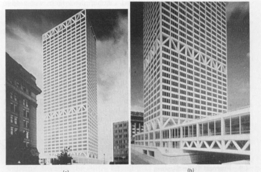
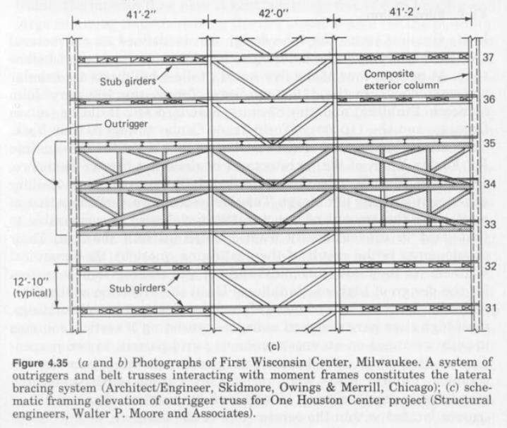
42 7. Outrigger-Braced Structures Various wind bracing techniques to save in steel tonnage and cost, namely the belt truss system, also known as outriggerbraced system. These system are more efficient than braced frames or a system of interacting braced and rigid frames. To control the building drift increase the column areas, however, the resulting high uplift forces can present foundation anchoring problems. The technique of outrigger can be very effective in enhancing the efficiency of shallow bracing systems, especially when two or more stiffening trusses are employed along the height of a building.
43 7. Outrigger-Braced Structures This efficient structural form consists of a central core, comprising either braced frames or shear walls, with horizontal cantilever outrigger trusses or girders connecting the core to the outer column (Fig. 4.16a).
44 7. Outrigger-Braced Structures When the structure is loaded horizontally, vertical plane rotations of the core are restrained by the outriggers through tension in the windward columns and compression in the leeward columns (Fig. 4.16b). The large, often two-story, depths of the outrigger and perimeter trusses make it desirable to locate them within the plant levels in the building. The degree to which the perimeter columns of an outrigger structure behave compositely with the core depends on the number of levels of outriggers and their stiffnesses. For buildings from stories high.
45 7. Outrigger-Braced Structures The purpose of providing more than one truss is to increase the strength and stiffness of the system over and above the beneficial effect of a single truss. At these levels, stiff outrigger arms are used to activate a perimeter truss, which in turn enforces the participation of the exterior columns in resisting wind loads.

46 7. Outrigger-Braced Structures
47
48
49 8. Frame-Tube Structures
50 8. Frame-Tube Structures The lateral resistance of frame-tube structure is provided by very stiff moment-resisting frames that a tube around the perimeter of the building. The frames consists of closely spaced column, 6-12 ft (2-4 m) between centers, joined by deep spandrel girders.
51 8. Frame-Tube Structures When the lateral loadings acts, the perimeter frame aligned in the direction of loading act as the webs of the massive tube cantilever, and those normal to the direction of the loading act as the flanges. The tube is suitable for both steel and reinforced concrete construction and has been used for building ranging from 40 to more than 100 stories.
52 8. Frame-Tube Structures Advantages: 1. The highly repetitive pattern of the frames lends itself to prefabrication of steel and to the use of rapidly movable gang forms in concrete, which make for rapid construction. 2. It offers a relatively efficient, easily constructed structure, appropriate for use up to the greatest of heights.
53 8. Frame-Tube Structures Disadvantages: 1. The close spacing of the column throughout the height of the structure is usually unacceptable at the entrance level. The column are therefore merged, or terminated on a transfer beam, a few stories above the base so that only a few, larger, more widely spaced columns continue to the base. 2. The tube form was developed originally for building of rectangular plan, and probably is the most efficient use is in that shape. 3. The tube structure s efficiency although high, still leaves scope for improvement because the flange frames tend to suffer from shear lag ; this results in the mid-face flange column being less stressed than the corner column and, therefore, not contributing as fully as they could to the flange action.

54 8. Frame-Tube Structures A. Tube-in-Tube or Hull-Core Structure This variation of the framed tube consists of an outer framed tube, the hull, together with an internal elevator and service core.
55 8. Frame-Tube Structures B. Bundled-Tube Structures This structural form is notable in its having been used for the SearsTower in Chicago. This tower consists of four parallel rigid steel frames in each orthogonal direction, interconnected to form nine bundled tubes (Fig. 4.13a).

56 The SearsTower, Chicago
57 8. Frame-Tube Structures Advantage was taken of the bundled form to discontinue some of the tubes and reduce the plan of the building as stages up the height (Fig. 13b, c and d).
58 8. Frame-Tube Structures C. Braced-Tube Structures Potential for use to even greater heights as well as allowing greater spacing between the column, is add diagonal bracing to the faces of the tube. In the steel tube the bracing traverses the faces of the rigid frames, whereas in the concrete structure the bracing is formed by a diagonal pattern of concrete window-size panels, poured integrally with the frame.

59 8. Frame-Tube Structures The structure behaves under lateral loading more like a braced frame, with greatly diminished bending in the member of the frames. Consequently, the spacing of the column can be larger and depth of the spandrels less, thereby allowing larger size windows than in the conventional tube structure. Chicago s John Hancock building, (Steel braced tube)

60
61 9. Suspended Structures The suspended structure consists of a central core, or cores, with horizontal cantilevers at roof level, to which vertical hangers of steel cable, rod, or plate are attached. The floor slabs are suspended from the hangers
62 9. Suspended Structures Advantages: 1. Primarily architectural in that, except for the presence of the central core, the ground story can be entirely free of major vertical member, thereby allowing an open concourse. 2. The hanger are in tension and consequently can be of high strength steel, have a minimum sized section and are therefore less obtrusive. 3. During construction, it allowing the core, cantilever and hangers to be constructed while the slabs are being poured on top of each other at ground level, the slabs are then lifted in sets and fixed in position.
63 9. Suspended Structures 4. The benefits of such multi-core hanging structures include large open floor spaces at all levels, and the possibility of column-free ground story. Disadvantages: 1. The need to proof the hangers against fire and rust, thereby significantly increasing their bulk. 2. Inefficient in first transmitting the gravity loads upward to the roof-level cantilevers before returning them through the core to the ground. 3. Structural width of the building at the base is limited to the relatively narrow depth of the core, which restricts the system to buildings of lesser height.
64 9. Suspended Structures The problems can be limited by restricting the maximum number of floor supported by a single length of hanger to about 10 and by having multilevel cantilever systems.
65 10. Core structures Single core serves to carry the entire gravity and horizontal loading. In some cases, the slabs are supported at each level by cantilevers from the core.
66 10. Core structures Advantage: 1. System are mainly architectural, in providing a column-free perimeter at ground level and at other levels just below the cantilevers. Disadvantage: 1. Inefficient in resisting lateral loading, as well as in supporting the floor loading by cantilevers a highly inefficient structural component.

67 11. Space Structures The primary load-resisting of the space structure consist essentially of a threedimensional triangulated frame as distinct from an assembly of planar bents whose members serve dually in resisting both gravity and horizontal loading. This result is a highly efficient, relatively lightweight structure with a potential for achieving the greatest heights.

68 11. Space Structures Hong Kong Bank of China, 76 stories
69 11. Space Structures It usually geometrically complex, which call for considerable structural ingenuity in transferring both the gravity and lateral loading. One solution is to have an inner bracedcore, which serves to collect the lateral loading and the inner region gravity loading. At the bottom of each region, the lateral and gravity loads are transferred out to the main joints of the space frame.
70 11. Space Structures Disadvantage: 1. The multidirectional inclined member of the space frame are structurally awkward and costly to connect, as well as making the fenestration difficult. Advantage: 1. Visually interesting and aesthetically very pleasing in its apparent simplicity.
71 12. Hybrid Structures Many of previously described structural arrangements are particularly suitable for prismatically shaped, tower or block, so-called modern buildings, which can be complete structured by a single identifiable system, for example, a tube or a wall-frame. Building of a non-prismatic shape are less amenable to a single form or structure and therefore, the engineering has to improvise in developing a satisfactory structural solution.
72 12. Hybrid Structures In such situations combinations of two or even more of the basic structural forms have often been used in the same building either by direct combination as, for example, in a superimposed tube and outrigger system, or by adopting different forms in different parts of the structure as, for example, in a tube system on three faces of the building and a space frame on a faceted fourth face.
73 12. Hybrid Structures


74 12. Hybrid Structures Taipei 101, 2004

75 12. Hybrid Structures Bird Nest Olympic 2008
76 Summary The structural form of a high-rise building is influenced strongly by its function, while having to satisfy the requirements of strength and serviceability under all probable conditions of gravity and lateral loading. Other influential factors include the building s material of construction, its accommodation of services and its overall economy. The taller a building, the more important it is economically to select an appropriate structural form.