Birsta 3PH2b WORKING DESCRIPTION INSTALLATION, REPAIRS AND MAINTENANCE. Doc. No.: Birsta 3PH2b - Rev. 0
|
|
|
- Elmer Morton
- 5 years ago
- Views:
Transcription

1 Birsta 3PH2b WORKING DESCRIPTION INSTALLATION, REPAIRS AND MAINTENANCE Doc. No.: Birsta 3PH2b - Rev. 0
2 Working Description Prepared by: Fredrik Sangö Doc. no.: Birsta 3PH2b Introduction/data: Birsta 3P has been full-scale tested according to EN (TB11 and TB52) and CE marked in accordance with EN : a2:2012 for containment level H2 (No CPR - SC ) The results from the test were working width W3 and vehicle intrusion VI4. The tested length was 52 meters plus end anchors. The installation work can be broken down into the following 10 steps, which will be processed individually in the work description in the order shown below. 1) Planning 2) Unloading of material 3) Proprietary inspection 4) Safety 5) Establishment 6) Installation 7) Repairs to zinc damage 8) Demobilisation 9) Repairs 10) Maintenance Chap. 11 includes additional information (drawings, CE certificates and DoP). Rev. no. Date Signature Reason for revision Fredrik Sangö Approved by Birstaverken Birstaverken AB - Birstavägen 10 - S Sundsbruk - Tel: +46 (0) Fax: +46 (0)
3 Birsta 3PH2b Page 3 INSTALLATION, REPAIRS AND MAINTENANCE Birsta 3PH2b - Rev. 0 WORKING DESCRIPTION Contents 1 PLANNING UNLOADING OF MATERIAL PROPRIETARY INSPECTION SAFETY ESTABLISHMENT INSTALLATION REPAIRS TO ZINC DAMAGE DEMOBILISATION REPAIRS MAINTENANCE OTHER INFORMATION... 9
4 Birsta 3PH2b Page 4 INSTALLATION, REPAIRS AND MAINTENANCE Birsta 3PH2b - Rev. 0 WORKING DESCRIPTION 1 PLANNING It is at this point that the quality and flexibility of the project is determined. Well planned installation routines are a good basis when you are looking to achieve high quality, good logistics, work that is conducted safely and satisfied employees. All the parties involved should have discussed the preconditions for the installation in good time and agreed on how it should be done. It is important that both the client and the contractor are aware of the undertakings that each other have agreed to. These are best coordinated through good contacts. Plan deliveries and installation in a timely manner. All the parties involved must keep each other notified as to any changed circumstances. 2 UNLOADING OF MATERIAL The material is unloaded and suitably placed where the installation is to be carried out. This is to ensure that any unnecessary handling in the workplace can be avoided. Handle the material carefully, use wood pieces as support for material that is not placed on pallets. When unloading, check that the unloaded goods match the delivery note. The goods must be checked to ensure that no damage is present. Non-conformance regarding package quantities or damages must be indicated on the delivery note and the sender must be contacted immediately. 3 PROPRIETARY INSPECTION Assembly personnel are to perform and report, in the appropriate documents, proprietary inspections which must include the minimum of the following points: Inspection points for installation in settings with traffic: The material is checked for damage and quantity following delivery to the worksite The curvature is checked The height is checked All bolt joints are fitted and tightened The opening in the joints is according to the drawings If dilation joints should be installed, this should be checked according to the drawing of the dilation joint. If infill should be installed, this should be checked according to the drawing of the infill. Any minor damage to the galvanizing or painting is treated
5 Birsta 3PH2b Page 5 INSTALLATION, REPAIRS AND MAINTENANCE Birsta 3PH2b - Rev. 0 WORKING DESCRIPTION 4 SAFETY As installation is often performed in a busy setting, the safety aspect is crucial. Temporary barriers (if needed) must be adapted to ensure that installation can be performed without them being removed. 5 ESTABLISHMENT Assembly personnel must be notified or be privy to the conditions prevailing in the workplace by the time of establishment at the latest. 6 INSTALLATION The installation description assumes that the company responsible for the installation has ensured that the assembly personnel have the necessary expertise with regard to the safety barrier components, terms and bolt dimensions, etc., see drawings in Chap This information is available in the drawings. These are attached at the end of this description. Each bolt must be tightened with a normal torque. Setting out: Installation of posts: Before installation can commence, the location for the posts must be set out. This requires great accuracy. Setting out is done according to the drawing. NOTE: The cc-dimension runs parallel with the roadway (inclined dimensions). 1- Start the installation with the post support: a. Bolt group: For installation with bolt groups remove concrete from the bolts (if needed). Inspect the bolts for visible damage. Add installation lubricate or wax to the bolts before assembling the nuts. Start with the nuts to be installed below the base plate (check location and heights). Note add washer before the posts are located at the bolt groups. b. Casted into edge beam or concrete foundation: Inspect the holes (cleanness, depth, shape and water). The holes should be scratched. Install the posts in the holes. c. Steel foundation (Post with integrate steel foundation): i. Before installation can commence, the location for the posts must be set out. This requires great accuracy. Setting out is done according to the
6 Birsta 3PH2b Page 6 INSTALLATION, REPAIRS AND MAINTENANCE Birsta 3PH2b - Rev. 0 WORKING DESCRIPTION drawing. NOTE: The cc-dimension runs parallel with the carriageway (inclined dimensions ii. Installation of posts: The posts can be installed with different methods (depending on the post type and ground condition): a. Ramming the post b. Pre-drilled or pre-punched holes. The post must be fitted immediately after hole drilling/punching. Special equipment is needed for pre- punching holes in order to minimize damage in the asphalt and to optimize stability of the post. Note: If the ground where the pre-boring or pre-punched occurs is perceived as loose, the site management must be notified. 2- The installation continues with the top rail. A crane may be need for lift assist. The installation of the top rail starts at one end of the bridge (or road). The top rails should be located according to the specification for the project. All joints (bolts) are first assembled by hands (without tools). The joint pipe is mounted in the first top rail. Put the next top rail at the joint pipe and continue until all the top rails are mounted. 3- Install the deformation element for the rails and if required the brackets for the infill. 4- Install the rails (use the procedure for the top rail). 5- Final, inspect the installation and tightening each bolt with a normal torque. 6- If needed, Grouting / Casting: Perform under grouting of base plate. Casted post should be casted in the hole. 7- If needed, install the infill.
7 Birsta 3PH2b Page 7 INSTALLATION, REPAIRS AND MAINTENANCE Birsta 3PH2b - Rev. 0 WORKING DESCRIPTION 7 REPAIRS TO ZINC DAMAGE Repairs to any zinc damage in the delivered materials are carried out according to SS/EN-1461 and Industry Standard - finishing and repairs. Zinc damage must be treated as follows: Scratches and elongated spots narrower than 2 mm and less than 10 cm 2. No action required. Damage wider than 2 mm and less than 3.16x3.16 cm (or less than 10 cm 2 )must be rectified by painting with zinc-rich paint. It is also possible to use a suitable zinc paste, zinc flakes or alloyed sticks. Before any repairs are made, clean with a stainless steel brush. Damages larger than 10 cm 2 must be re-galvanized. 8 DEMOBILISATION Inspection regarding heights and general visual impression. A proprietary inspection in accordance with point 3 must be conducted and completed, and copies forwarded to the client (customer). Following the proprietary inspection the safety barrier is marked with a CE Mark (on the first and last post in the CE-marked safety barrier. Where necessary, an additional CE Mark can be set up between the first and last posts).
8 Birsta 3PH2b Page 8 INSTALLATION, REPAIRS AND MAINTENANCE Birsta 3PH2b - Rev. 0 WORKING DESCRIPTION 9 REPAIRS All damaged material must be replaced immediately. Damage means that the steel is weakened such as deep scratches, rips, creases and suchlike. Damaged material must be replaced with genuine parts. Replacing damaged components following a collision is no different from a normal installation besides the disassembly operation. Bear in mind that there may be a lot of tension in the safety barrier that has been hit. 10 MAINTENANCE A minimum of maintenance includes rinsing with clean water where necessary followed by a visual inspection for damage.
9 Birsta 3PH2b Page 9 INSTALLATION, REPAIRS AND MAINTENANCE Birsta 3PH2b - Rev. 0 WORKING DESCRIPTION 11 OTHER INFORMATION 11.1 Drawings: Page CE Certificate: Page Declaration of Performance (DoP): Page 18.
10 Page 10
11 Page 11
12 Page 12
13 Page 13
14 Page 14
15 Page 15
16 Page 16
17 Page 17
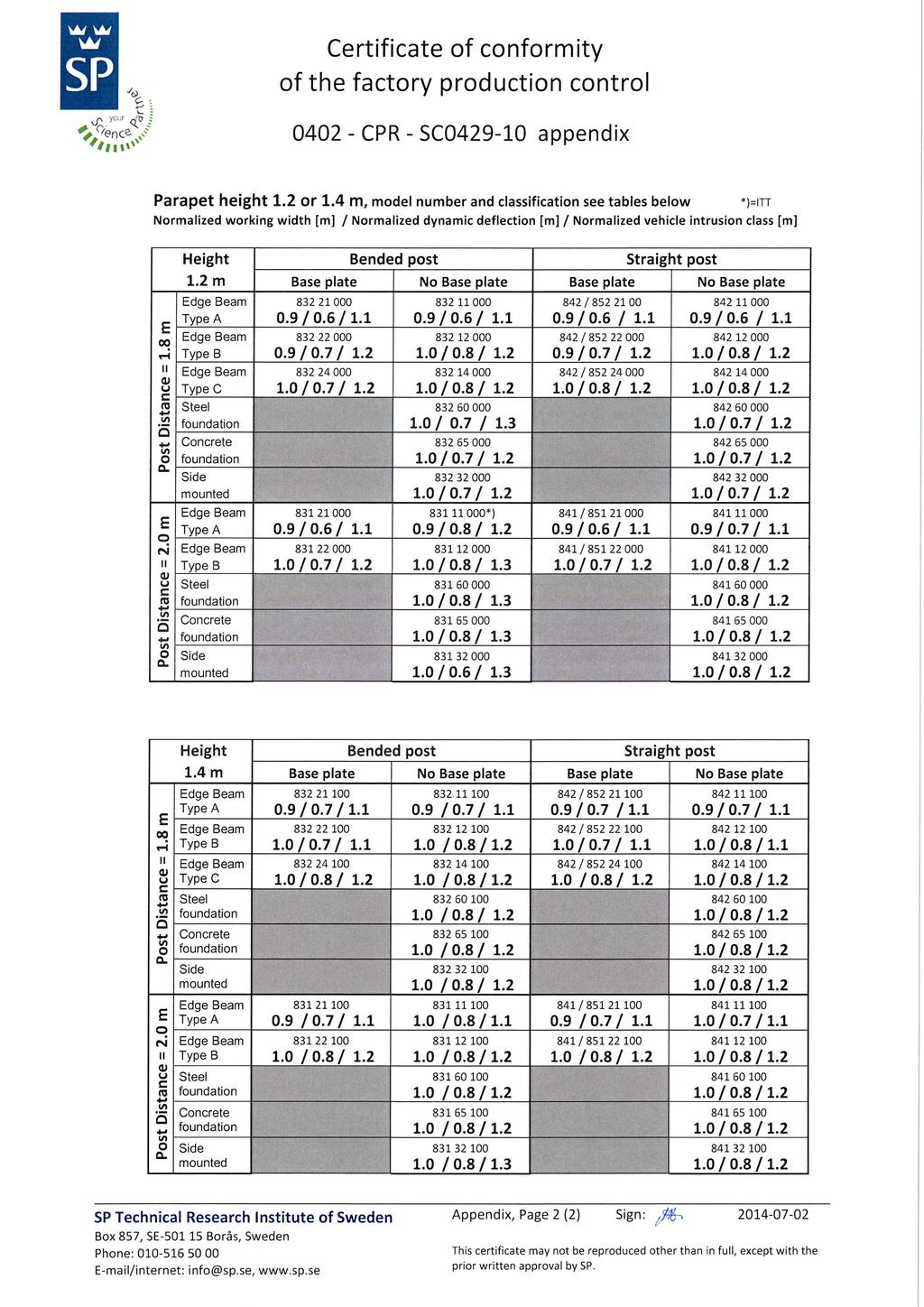
18 Page Manufacturer DECLARATION of PERFORMANCE (DoP) No. Birsta 3PH2b Birstaverken AB Box 30, SE Sundsbruk, Sweden Telephone: Web: Product identification code Birsta 3PH2b Single sided safety barrier c/c m. Height m. Edge beam: -100 to 100 mm. Base plate, steel foundation, concrete foundation, side mounted or post casted into concrete edge beam. Product type Birsta 3PH2b Intended use In vehicle circulation areas Harmonised standard EN :2007 / A2:2012 System of assessment and verification System 1 (CPR no. 305/2011) Name of notified body SP Technical Research Institute of Sweden Identification number of the notified body No Certificate of constancy of performance No CPR-SC Declared performances Essential characteristics Performance Harmonised standard Performance under impact: - containment level H2 EN :2007 / A2: impact severity B EN :2007 / A2: normalized working width W3 * EN :2007 / A2: normalized vehicle intrusion VI4 * EN :2007 / A2: normalized dynamic deflection EN :2007 / A2:2012 * Value see Certificate of constancy of performance No CPR-SC Resistance to snow removal: Class 4 EN :2007 / A2:2012 Durability: - of performance under impact Hot dip galvanized coatings according to EN ISO 1461 * EN :2007 / A2: of resistance to snow removal Hot dip galvanized coatings according to EN ISO 1461 EN :2007 / A2:2012 The performance of the product is in conformity with the declared performance. This declaration of performance is issued under the sole responsibility of the manufacturer. Signed for and on behalf of the manufacturer by: Fredrik Sangö, Senior Technical Adviser Sundsvall
19 Main Office Birstaverken AB Birstavägen 10 Box Sundsbruk Sweden Tel: Fax: Arboga Office Kapellgatan 29 Box Arboga Sweden Borås Office Viaredsvägen Borås Sweden