Webinar 2014-May-28. Balancing your Die for Optimum Extrusion
|
|
|
- Horatio Palmer
- 5 years ago
- Views:
Transcription


1 Webinar 2014-May-28 Balancing your Die for Optimum Extrusion

2 Webinar 2014-May-28 Balancing your Die for Optimum Extrusion Vince Lombardi Perfection is not attainable. But if we chase perfection, we can catch excellence


3 Webinar 2014-May-28 Balancing your Die for Optimum Extrusion Key points about Extrusion Dies and Clay Products Manufacturing It is not possible to make a one die fits all clay extrusion operations. Most clay extrusion dies have some custom detail to help achieve the highest quality brick for your raw material, operation, product you are manufacturing, size, shape, ASTM specification, void, rate, and etc.. To achieve a quality manufactured clay product, attention to detail does matter. Extrusion dies wear, nothing last forever. We build a die that every component can be re-lined so you can maintain your extrusion quality. If you change your raw material even just change the percentage of the different materials, it can effect how the material extrudes. Worn extrusion augers and liners effect how raw material flows through a die, and also how much heat is generates. The point I am making is someone has to be looking and someone has to know what to look for. The day you think you know everything about brick manufacturing is the day you get a reality check. Put fail safes and documentation in place so issue do not repeat themselves. Try new things, you never know you may build in some wiggle room to help you through the ebb and flow of outside influences. Any problem that is solved in a brick plant is lived by the folks that work there and outside resources that are committed enough to live the problem with you. The outside resource should care enough to make your problem their problem. The Goal: To make Extrusion Dies that compacts the raw material and clay as it flows through the die, creating the least amount of stress and heat as possible.
4 Method To Check Die Balance It is important that the bump test be done as quick as possible 1-4 from the face of the cap is ideal. Before performing a bump test all normal extrusion parameters must be obtained: Temper, Tonnage, and lubrication pressure Bump Test
5 Bump Test Process
6 Once all parameters have been achieved stop extrusion and cut a section of material away. Cut the material as precisely as possible to the face of the cap as shown. Bump Test Process

7 Bump Test Process Material cut even with the cap
8 Jog the extruder on and off as fast as possible, just to bump out 1-4 of column. Bump Test Process Bump / Jog the extruder
9 Bump Test Process Results of a bump test

10 Bump Test Process Use a tape measure to determine the results. You should not have more than a ½ deviation in measurements
11 Bump Test Process A bump test is used to check for unusual flow through the die. If something unusual is noticed, a grid test should be performed at this point. A bump test should be performed at least three times consecutively to assume accuracy. A grid test, as rule of thumb, should show no more than one inch out of square within twelve feet of the extruded column. A grid test should be performed at least two times consecutively to assume accuracy.
12 Grid Test Process You should have as many vertical wires as you have rows of cores. If you are running a three hole you should have three vertical wires. five hole five vertical wires. Single bar bridge should have one horizontal wire. Double bar bridge should have two horizontal wire.
13 Once all parameters have been achieved stop extrusion and cut a section of material away. Cut the material as precisely as possible to the face of the cap as shown. Grid Test Process
14 Ensure sure extruder is full. Ensure column temper is normal. Ensure lubrication is normal. Mount the wire frame securely to the cap. Ensure sure you have enough horizontal and vertical wires. Line wires up with the center of each row of core vertically. Line wires up in the center of each row of cores horizontally. Ensure wires are very tight. Grid Test Process
15 Have enough people available to hold all clay streams together. Turn extruder and pug sealer on. Run out of material. You should have less than 1 of difference in the length of the individual clay streams. You should have at least two consecutive results before making any changes. Grid Test Process
16 When should die balance be checked? A simple bump test show be done every time you do a change over. If you have not changed over in a week you should do a bump test. If parts are changed such as cores, bridges, or caps you should do bump test. If you do a body change you should do a bump test. If you are more than a ½ out on a bump test do a grid test.
17 What influences Die Balance? Proper die set-up and installation Proper mounting of a die Column support after the die Velour frame alignment Off take belt, texturing beam, texturing equipment Bridge and Core Design Percentage of Void Field Corrections More Permanent Corrections Rear opening of the die compared to the auger size Die Lubrication Interruptions in clay flow reverse lips within the die Inconsistent material throughput Inconsistent material temper/moisture content/ vacuum

18 Proper Die Set-up and Installation Bridge should be center right to left. Bridge should be centered up and down. Why? Bridge Set-Up What is WRONG with this picture?

19 What will happen if a bridge is set up too high like this one? Answer: Material flow is easier on the bottom, so the material will travel fast on the bottom and the column will extrude upward. Proper Die Set-up and Installation Bridge Set-Up
20 What will happen if a bridge is set up too low like this one? Answer: Material flow is easier on the top, so the material will travel fast on the top and the column will extrude downward. Proper Die Set-up and Installation Bridge Set-Up

21 What will happen if a bridge is set up too far to the right like this one? Answer: Material flow is easier on the left, so the material will travel fast on the left and the column will extrude to the right toward the thinner header shell. Proper Die Set-up and Installation Bridge Set-Up
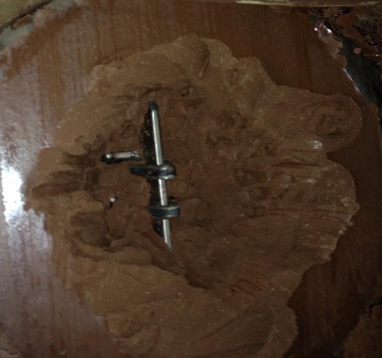
 bolts that are used to adjust the bridge: left, right, up, and down. Bridge is easiest adjusted during operation or clean.")
22 Reymond Die Adjustable Bridge Feature bridge set-up and maintainability of bridge easy. Bridge is externally adjustable from the outside of the unit. On each side of the unit you will find (3) bolts that are used to adjust the bridge: left, right, up, and down. Bridge is easiest adjusted during operation or clean. It is important not to over tighten the mounting bolts so that the bridge can be adjusted. Proper Die Set-up and Installation Bridge Set-Up

23 All Die combinations are figured so that the cores are recessed 1/16 ( mm) inside the face of the cap. This insure you get final compaction around the core at final cap size. Core outside the cap can result in header cracks. Proper Die Set-up and Installation Bridge Set-Up Proper Inset of Core within the Cap This is not necessarily a balance issue but we see this detail missed so many times. This happens when people buy cores that are longer than the original supply.


24 This becomes increasing important on high void units like this 50% void product. Proper Die Set-up and Installation Bridge Set-Up Proper Inset of Core within the Cap

25 Video Proper Die Set-up and Installation Bridge Set-Up Proper Inset of Core within the Cap

26 Proper Die Set-up and Installation Bridge Set-Up Proper Inset of Core within the Cap Video

27 Proper Mounting of A Die Mount the unit firmly against the extruder, hinge door, or die changer. Align die center of the point auger, die should have a know center, extruder should have a center line. Evenly mounted top to bottom and right to left. We recommend starting right up as close as you can get to the point auger. It takes less energy to extrude that way. Some products like pavers may need extension rings.

28 Column Support After Exiting the Die Proper column support should allow the column to exit the die level. The column should also be square with the column support. NOT SO GOOD GOOD


29 Column Support After Exiting the Die Attention to detail produces good results. GOOD NOT SO GOOD Lack of Attention to detail produces bad results.

30 Mount frame secure. Mount same distance from the die right to left up and down. If you trim one side sooner than the other you can create a drag and pull toward the side trimmed first. Trimming more on one side than the other can create a drag on the heavy trimmed side. Trimming more on one side is not a fix for a bridge not being centered. Velour Frame Alignment Trimming too much is not Good it: Cuts out compaction Slows extrusion Waste energy Returns too much de-aired material that will extrude different and cause balance issues. Also can cause lamination.

31 Video Texture Beam, Off Bearing, Texture

32 Video Texture Beam, Off Bearing, Texture

33 Texture Beam, Off Bearing, Texture
34 Texture Beam, Off Bearing, Texture What you do down stream of the die can effect the back pressure on the die. If you have a column pushing one way, and uneven depth of a texture roller may be pushing the column. A texture beam or off take belt that is not square with the die can push a column. Then most people push it back with a roller on the other side of the column and this stresses the brick. Deep textures can cause more column swell. Most people running deep textures are running very stiff columns.
35 Bridge and Core Design Effect Clay Flow Typical set-up for Modular Brick in the USA. Three Hole Modular
36 Bridge and Core Design Effect Clay Flow Typical set-up for Modular Brick in the USA. Ten Hole Modular

37 Bridge and Core Design Effect Clay Flow Points to understand about a Ten Hole Set-up Double bar bridge Thinner Webs More Flow Restrictions in the center


38 Bridge and Core Design Effect Clay Flow Points to understand about a Three Hole Set-up Single bar bridge Thicker Webs Less Flow Restrictions in the center

39 Bridge and Core Design Effect Clay Flow Results Of Less Flow Restrictions in the center Bump Test Result

40 Bridge and Core Design Effect Clay Flow Results Of Less Flow Restrictions in the center This is obvious. Not so obvious

41 Bridge and Core Design Effect Clay Flow Results Of Less Flow Restrictions in the center Fired Test Result Bowed Brick


42 Bridge and Core Design Effect Clay Flow Results Of Less Flow Restrictions in the center Vertical Face Cracks Dog earing Generally corrected by slowing middle down or speeding up outside Generally due to slow outside, corrected with lubrication


43 Bridge and Core Design Effect Clay Flow Bridge Design Custom built for your material needs. Sized for your needs. Pins centers are made to your needs. Spacing is for your material needs. Thickness is built for your material needs. Knitting grooves are machined into each bar to help promote knitting of material.


44 Bridge and Core Design Effect Clay Flow Bridge Design Do these look anything like original supply? Sharp bridges can cause header cracks Bridge built up larger than the design can cause High amperage Restricted flow Balance change Poor Quality Practices like this will not save you money they will only cause quality issues. I do not understand why my cores keep moving around. What? I need that knitting groove?
45 Bridge and Core Design Effect Clay Flow None cored units are generally fast in the center Corrections for flow on none cored units: Extension Ring Bulges Dummy Bridges Geometry


46 Percentage Of Void Effect Clay Flow

47 Percentage Of Void and Effect Clay Flow Grid test at initial start-up

48 Field Corrections Bridge Clips

49 Field Corrections Bridge Clips Grid test after adding bridge clips

50 Video Percentage Of Void Effect Clay Flow Field Corrections Bridge Clips

51 Percentage Of Void Effect Clay Flow Field Corrections for a fast center Bridge Clips


52 Field Corrections Bridge Clips


53 Field Corrections Telescoping the Die Center of column running too fast move the die away from the point auger Center of column running too slow move the die toward the point auger

54 Field Corrections Sleeves

55 More Permanent Corrections Staggered Coring

56 Length of Die Rear Die Opening Bridge Design Internal Geometry Angels Tapers Bulges Percentage Of Void Effect Clay Flow More Permanent Corrections

57 Aggressive scoring can slow flow on the bottom of the brick. Changes to the bridge may be necessary. Changes to the liners in the die may be necessary. Bulges in the top of the die may be used. Scoring Effect Clay Flow
58 In soft extrusion lubrication is not as important because the material is more fluid. In stiff extrusion lubrication is a necessity in most cases. Why use Lubrication? Longevity of the interior of the die surfaces. Ease of material flow/die balance. Reduction of column temperature and internal stress. Die Lubrication Effect Clay Flow

59 Lubrication Lips 1/8 Lips between each mating part act as lubrication reservoir. This requires less lubrication pressure from the lube pump. Without the lips you cause lubrication penetration because the lube has nowhere to go but in the column. Number of lubrication points is dictated by: Size of product Void Shape Length of die needed to extrude a quality product Die Lubrication Effect Clay Flow
60 Multiple Pump Lubrication Using two pumps eliminates the use of pressure regulators. Allows overall superior lubrication control. Pinpoint volume and pressure. Becomes a necessity in high production factories to be able to supply enough lubrication volumes in the correct location. Die Lubrication Effect Clay Flow
61 Die Lubrication Effect Clay Flow Use a die lube that will stay on the outside of the clay column. Penetration cause lamination and header cracks. We recommend water soluble soap based lubricates like our RP3 Or soybean oil like our Lubrick Diesel is not a good die lube it does not have a high enough viscosity
62 Interruptions in Clay Flow Reverse Lips within the Die Reverse Lips Cause lubrication penetration. Promote lamination from clay running over clay. Cause dry clay pieces to release, which causes torn webs and dry patches. Cause dog earing or corner tearing. Create drag which results in heat generation and internal stress. Reverse lip Reverse lip

63 Interruptions in Clay Flow Reverse Lips within the Die Blount Cores verses Tapered Cores Blount cores can create lamination. Blount cores can create interruption of clay flow. Blount cores create less compaction. Tapered core promote even flow. Tapered cores promote knitting. Tapered cores create better compaction.

64 Negative Effects: Inconsistent column density. Inconsistent die balance due to change in column density. Inconsistent column speed More column shifting as auger turns. Lubrication penetration due to column slowing down. Lamination due to low column density. Lower productivity. Inconsistent product quality. Inconsistent Material Throughput Effects Incorrect Auger Feed

65 Positive Effects: Consistent column density. Consistent die balance due to consistent column density. Consistent column speed. No column shifting as auger turns. No lubrication penetration. No lamination. Increase productivity. More consistent quality product. Inconsistent Material Throughput Effects Correct Auger Feed
66 Inconsistent Material Temper, Moisture Content, and Vacuum Causes: Low column density Variation in size Variation in texture Distortion Low green strength Changes in column temperature Internal stress Down time due to handling equipment Lower product yield Downgraded product Overtime Little to no profit