MULTIBLADE FIRE DAMPER BSK-J/EI90
|
|
|
- Hilda Baker
- 5 years ago
- Views:
Transcription

1
2 MULTIBLADE FIRE DAMPER BSK-J/EI90 Table of contents: MULTIBLADE FIRE DAMPER BSK-J/EI90 - OVERVIEW... 3 FIRE DAMPER EI90 - GENERAL INFORMATION... 4 MULTIBLADE FIRE DAMPER BSK-J/EI90 - DIMENSIONS AND WEIGHTS... 5 MULTIBLADE FIRE DAMPER BSK-J/EI90 DESIGN AND INSTALLATION... 6 MULTIBLADE FIRE DAMPER BSK-J/EI90 - DESIGN AND INSTALLATION... 7 MULTIBLADE FIRE DAMPER BSK-J/EI90 - INSTALLATION WITH SOFT SEAL... 9 MULTIBLADE FIRE DAMPER BSK-J/EI90 - INSTALLATION WITH SOFT SEAL COMBINED PENETRATION SEAL MULTIBLADE FIRE DAMPER BSK-J/EI90 - INSTALLATION WITH SOFT SEAL IN SINGLE-SIDED COVERED THIN SHAFT WALL MULTIBLADE FIRE DAMPER BSK-J/EI90 - INSTALLATION WITH SOFT SEAL IN SINGLE-SIDED COVERED THIN SHAFT WALL MULTIBLADE FIRE DAMPER BSK-J/EI90 DETAIL INSTALLATION TYPES AND TECHNICAL SPECIFICATIONS MULTIBLADE FIRE DAMPER BSK-J/EI90 INSTALLATION DETAILS INSIDE SOLID WALLS MULTIBLADE FIRE DAMPER BSK-J/EI90 - INSTALLATION DETAILS FOR OUTSIDE OF AND ONTO SOLID WALLS MULTIBLADE FIRE DAMPER BSK-J/EI90 - INSTALLATION DETAILS INSIDE SOLID CEILINGS MULTIBLADE FIRE DAMPER BSK-J/EI90 - OUTSIDE OF AND ONTO THE SOLID CEILING STRUCTURE MULTIBLADE FIRE DAMPER BSK-J/EI90 - INSTALLATION DETAILS INSIDE LIGHTWEIGHT WALLS MULTIBLADE FIRE DAMPER BSK-J/EI90 - INSTALLATION DETAILS OUTSIDE OF AND ONTO LIGHTWEIGHT WALLS MULTIBLADE FIRE DAMPER BSK-J/EI90 - INSTALLATION WITH SOFT SEAL INSIDE SINGLE-SIDED COVERED THIN SHAFT WALLS MULTIBLADE FIRE DAMPER BSK-J/EI90 - INSTALLATION DETAILS FOR EDGINGS AND ADDITIONAL ISOLATION EDGINGS MULTIBLADE FIRE DAMPER BSK-J/EI 90 - HANGERS AND FASTENINGS MULTIBLADE FIRE DAMPER BSK-J/EI90 HANGERS AND FASTENINGS FOR OUTSIDE OF WALL CONSTRUCTION MULTIBLADE FIRE DAMPER BSK-J/EI90 - TECHNICAL SPECIFICATIONS MULTIBLADE FIRE DAMPER BSK-J/EI90 - GENERAL INFORMATION MULTIBLADE FIRE DAMPER BSK-J/EI90 - COMMISIONING AND INSPECTION CONTROLS MULTIBLADE FIRE DAMPER BSK-J/EI 90 INSIDE MORTAR PENETRATION SEAL, SOFT SEAL AND COMBINED PENETRATION SEAL MULTIBLADE FIRE DAMPER BSK-J/EI90 - TENDER SPECIFICATION TEXT
3 MULTIBLADE FIRE DAMPER BSK-J/EI90 - OVERVIEW BSK-J/EI90 Multiblade fire damper (below also damper) certified in compliance with requirements of EN Tested according to EN Installation inside the soft seals can be provided without external fire protection coating or another kind of external fire protection paneling. The fire damper is tested together with HILTI soft seal. It has to have equivalent material properties in case that other brands of soft seals shall be used due to some reason. Installation conditions must be satisfied in all cases as mandatory requirement! Release with usage of Thermal sensor. Actuator design 230 (24) V, always with BELIMO or GRUNER actuators equipped by return spring. Running time acc. appropriate actuator data-sheet. Fire resistance class: EI 90 (ve - ho i o) S Multiblade fire damper BSK-J/EI90 Width: mm Height: mm (150 mm increment) Mounting length: 200 mm + optional mounting part 100 mm Running time acc. to appropriate actuator datasheet Fire resistance class: EI 90 (ve - ho i o) S CE certification: according to EN Leak tightness: according to EN 1751 B/2 (external/internal) Cycles: according to EN CE Consistency of Performance Certificate no.: 1391-CPR-0208/2013 Declaration of Performance BSK-J/EI90 issued Damper axis: horizontal or vertical (actuator above or under the axe) Design: galvanized sheet steel 3 3
4 FIRE DAMPER EI90 - GENERAL INFORMATION Example Description: Multiblade fire damper ceritified with compliance of EN The new multiblade fire damper BSK-J/EI90 is tested acc. to EN The damper classification is EI 90 (ve - ho i o) S. The housing and the louver blades are made of fire resistant special-insulated fabric with silicate basis. The distance between strengthened blades inside the housing is 150 mm. Seal tightness per the room temperature (20 C) is achieved with special rubber section on touched edges of the damper. In the hot conditions the seal tightness of the blades is reached by special foaming material installed around the edges of the damper. The axis of the blades are equipped by heat-resistant bearings to ensure the function even in the fire. The connecting flange and the sheet metal parts are made of galvanized steel. The movement of the blades is synchronized. The actuator is placed directly on the axis, the actuator itself is extra thermally insulated. The mounting depth of the damper is 200 mm. Connector on the duct system is manufactured with a 30 mm diameter 4 corners hole flange. The seal tightness per the room temperature (20 C) is secured by the suitable silicone seals. The sealing element is in closed position formed and shaped by meshing of blades. In case of fire, heat expanding seal placed in-between the blades closes the fire damper hermetically. In case of fire the fire damper is automatically closed by the force of actuator. Thermoelectric release mechanism is connected to an actuator by wire. Fire damper can be equipped with following actuators: ACTUATOR BELIMO: BLF 24-T (-ST) BF 24-T (-ST) BLF 230-T BF 230-T ACTUATOR GRUNER: 340TA TA TA TA TA TA-230 Activation temperatures of the multiblade fire damper with a actuator are 72 C and 95 C. By default, the fire dampers with 72 C are delivered. The other temperatures must be specified by order. The actuator guarantees the safety position. By default, the motor is placed on the right side, but it is possible at the request of the customer to be installed on the left side. The blade actuator consists of form-fitting linkage that is with all blades (interlinkingly) connected. The damper actuator is placed in the housing completely outside of the air flow, and in that way meets the requirements of hygienic favorable mounting parts with smooth inner surface, such as for ventilation systems in hospitals. The movement of the blades takes place completely in the housing. In case of fire, the side seals are allowing unobstructed expansion of the dampers. In case of larger dimensions >1050 mm, the fire damper is delivered in more parts. Multiblade fire dampers are tested with a variety of BUS control systems. For the details please check appropriate data-sheet. Keep in mind the following points when planning the ventilation system: In the area of the mechanism, minimum 150 mm space must be available for the moving of the damper axis. Installation: In accordance to table 3 the damper should be used only in following installations. The wall opening should be designed with the following dimensions: B1 = B mm, H1 = H+180 mm (considering the actuator box, see fig. 1). The given dimensions are minimal, by installation inside soft seal the guidelines of the soft seal manufacturer (e.g. HILTI) should be kept. Pay attention to horizontality and rectangularity during installation strictly. Smoothrunning shall be checked after the installation. The activation device as trigger element of the damper and the actuator must have free access. The installation must be done in accordance to installation requirements in all cases! In order to ensure the flawless function of the damper, the following points must be regarded absolutely: a) Maximum airflow velocity 15 m/s Maximum pressure difference 1200 Pa b) The dampers are in the air line installed by the way that they can place themselves in "open" position automatically when the fan is switched off or when the louver damper which is between the fan and the damper is switched off. c) The equal and steady air distribution must be ensured over the cross section of the damper. Dampers are designed for macroclimatic areas with mild climate environment according to EN The damper is designed for air without firm, fibrous, sticky or aggressive additives. 4 4
 or on the left side possible.")
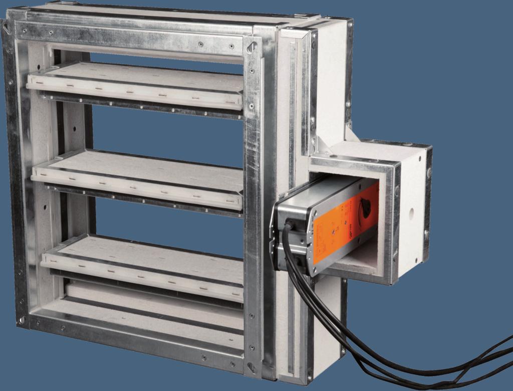
5 MULTIBLADE FIRE DAMPER BSK-J/EI90 - DIMENSIONS AND WEIGHTS Installation must be provided according to mounting requirements in all cases of installations (Inside, outside, onto). Installation position: Airflow should be horizontal and vertical, inlet or outlet side of the air is random. Actuator on the right (default) or on the left side possible. The position of the axis can be vertical (actuator above or under) or horizontal. The air direction arrows on the housing must always point upwards or horizontal. If version with the optional mounting part (9) is chosen, 9.5 kg must be added on the damper weight. Dimensions and weight: Fig. 1 Square multiblade fire dampers BSK-J/EI90 KEY: 1 wall of the housing, opposing the actuator 2 wall of the housing, upper / below 3 louver blades, upper / below 4 louver blades, intermediate Tab. 1 5 louver blades with drive axle 6 wall of the housing, actuator side 7 protective cover for the casing 8 protective housing for the actuator Multiblade fire dampers - dimensions and weights, standard length 200 mm + optional mounting part 9 top frame (option; 9,5 kg) 10 thermal sensor 11 actuator B x H Weight Aeff [m 2 ] Actuator type B x H Weight Aeff [m 2 ] Actuator type B x H Weight Aeff [m 2 ] Actuator type 200 x ,80 0,0098 BLF 500 x ,30 0,0257 BLF 800 x ,70 0,0416 BLF 200 x ,80 0,0290 BLF 500 x ,70 0,0761 BLF 800 x ,70 0,1232 BLF 200 x ,70 0,0483 BLF 500 x ,20 0,1266 BLF 800 x ,60 0,2049 BLF 200 x ,70 0,0675 BLF 500 x ,60 0,1770 BLF 800 x ,50 0,2865 BLF 200 x ,00 0,0868 BF 500 x ,40 0,2275 BF 800 x ,80 0,3682 BF 200 x ,00 0,1060 BF 500 x ,80 0,2779 BF 800 x ,70 0,4498 BF 200 x ,00 0,1252 BF 500 x ,30 0,3283 BF 800 x ,60 0,5314 BF 300 x ,30 0,0151 BLF 600 x ,70 0,0310 BLF 900 x ,20 0,0469 BLF 300 x ,70 0,0447 BLF 600 x ,70 0,0918 BLF 900 x ,60 0,1389 BLF 300 x ,20 0,0744 BLF 600 x ,60 0,1527 BLF 900 x ,10 0,2310 BLF 300 x ,70 0,1040 BLF 600 x ,60 0,2135 BLF 900 x ,50 0,3230 BLF 300 x ,50 0,1337 BF 600 x ,80 0,2744 BF 900 x ,20 0,4151 BF 300 x ,90 0,1633 BF 600 x ,80 0,3352 BF 900 x ,60 0,5071 BF 300 x ,40 0,1929 BF 600 x ,70 0,3960 BF 900 x ,10 0,5991 BF 400 x ,80 0,0204 BLF 700 x ,20 0,0363 BLF 1000 x ,70 0,0522 BLF 400 x ,70 0,0604 BLF 700 x ,70 0,1075 BLF 1000 x ,60 0,1546 BLF 400 x ,70 0,1005 BLF 700 x ,10 0,1788 BLF 1000 x ,50 0,2571 BLF 400 x ,70 0,1405 BLF 700 x ,60 0,2500 BLF 1000 x ,50 0,3595 BLF 400 x ,90 0,1806 BF 700 x ,30 0,3213 BF 1000 x ,70 0,4620 BF 400 x ,90 0,2206 BF 700 x ,70 0,3925 BF 1000 x ,60 0,5644 BF 400 x ,90 0,2606 BF 700 x ,20 0,4637 BF 1000 x ,50 0,6668 BF 5 5

6 MULTIBLADE FIRE DAMPER BSK-J/EI90 DESIGN AND INSTALLATION Tab. 2 Damper design BSK-J/EI90/M Damper design motorized fire damper with BLF 24-T motorized fire damper with BLF 24-T-ST motorized fire damper with BF 230-T motorized fire damper with BF 24-T-ST motorized fire damper with BLF 230-T motorized fire damper with BF 230-T motorized fire damper with 340TA-024 motorized fire damper with 340TA-024-ST motorized fire damper with 360TA-024 motorized fire damper with 360TA-024-ST motorized fire damper with 380TA-024 motorized fire damper with 380TA-024-ST motorized fire damper with 340TA-230 motorized fire damper with 360TA-230 motorized fire damper with 380TA-230 Installation BSK-J/EI/90 [BxH] M2 M3 M5 M6 M8 M10 G2 G3 G4 G5 G6 G7 G8 G9 G10 During the installation, the damper blade must be in "closed" position always. The damper in the fire protective isolating structure must be mounted in accordance to fig. 21. If this solution is not possible, the ventilation duct must be protected between the fire protective isolating structure and the damper blade in accordance to the certified installation type (see table 3- Installation type overview) and for the exact details for the additional insulation taken from the actual installation diagram and fig. 22. It is important to protect the actuator with a cover against damage and contamination, as long as the wall construction and plastering have not yet been carried out. The damper housing must not be deformed during the wall construction. After the damper installation, the damper blade must not ream against the housing during opening or closing. The distance between the fire damper and the supporting structure (wall, ceiling) must be minimally 75 mm. If two or more fire dampers should be installed in one sector, then the distance between the juxtaposed dampers must be at least 200 mm. Multiblade fire dampers - general installation directions:!!attention!! There is a risk of injury upon edges and sheet metal parts. During transport and installation, always wear protective gloves. The damper that have actuator with spring return, the thermoelectric actuation device that is connected with the actuator by wire, must be installed on the damper. It should be noted that the part of the activation device that protrudes into duct does not interfere with the free movement (the swivel range) of the damper blades. If the damper is with an add-on piece ordered, then the activation device is in the add-on piece installed. The wiring (connection of the actuator) must be produced by an authorized electrician, according to the current standards instructions. Installation position: The damper - BSK-J/EI90 is suitable for the installation in vertical or horizontal position with random blade position. The ensuing ventilation duct must be mounted or supported so that there is not any kind of load transmission from the ducting onto the damper flange. The fire damper has to be installed in a completely tensionless and right angled state. Sufficient room must be provided for maintenance and cleaning on the damper. An access opening must be provided for cleaning and inspection purposes of the damper. In order to ensure the necessary clearance to the controlling device it is recommended that the other objects have minimum 350 mm distance from the controlling parts of the damper. Fig. 2: The distance between the multiblade fire damper and the structures required by EN normative Installation with soft seal: The soft seal must have the dimensions of W x H =1650 x 2050 mm or W x H = 2050 x 1650 mm. The maximum edge distance must not exceed 400 mm! If the size, in accordance to ETA / ETA tested, of blank seal is not exceeded, there are no specifications for the maximum edge distance. Firestop boards: Brand HILTI Firestop Board CFS-CT B 1S 140/50 Coating: Brand HILTI Firestop Coating CFS-CT Boards bonding: Brand HILTI Acrylic Sealant CFS-S ACR 6 6
7 MULTIBLADE FIRE DAMPER BSK-J/EI90 - DESIGN AND INSTALLATION The lightweight walls must be prepared by the way that they do not sway the function of the soft seal over the fire resistance period. Lightweight walls must not affect the function of the isolation over the fire resistance period, even in case of possible deformation in the event of fire. (e.g. damage / displacement of the isolation relating to the fire damper/ smoke control damper due to deflection of the wall in the event of fire. When installing more fire dampers, the following points must be considered: The given measurements are based on the installation with the HILTI products. If other brands of soft seals are used, it has to have equivalent material properties and installation conditions must be satisfied! If the size of the soft seal is bigger than the size tested in accordance to ETA / ETA, then the maximum edge distance must not exceed 400 mm. Also, in a seal could be combined the dampers with horizontal and vertical axis. The dampers can be installed outside of the wall, or ceiling structure. The ventilation duct and a part of the damper, between the wall structure and the damper blade must be protected with fire insulation. The allowed types of installation are given in the table 3 and in the corresponding illustrations of the instructions for the additional insulation. By the installation outside of the wall structure or inside the opening, damper must not hang on by its own weight. See fig. 24 and fig. 25. The installation of the damper must be provided according to installation conditions. The fastening, in the event of fire, endures the whole fire resistance period (90 min) and the displacement of the damper is excluded. The dampers must be installed without deformations or damages. The right-angled installation must by secured. Free movement shall be checked after the installation. In any case it should be ensured, that the fire resistance of the whole structure (wall / ceiling / fire damper) is not in any way by installing. Mounting, maintenance, control and inspections of the operating capability must be done by an expert in accordance to directions as well as installation requirements. For the reliable operation of the dampers is important to note, that it does not come to obstruction of the closing mechanism and the sealing surface of the damper blades through dust, fibrous or sticky materials and solvent. Control of the damper actuator without power supply: It is possible to manually adjust the damper blade in random position using the special tool (actuator's accessory). By turning the tool in the arrow direction, the damper blade is moving to the opened position. The damper blade stays in random position by shortly turning the tool (½ turn) in the opposite direction of the arrow. Resetting is performed either manually by turning the tool in the arrow direction or by adding the supply voltage. Activation and control of the function: After the installation, the movement of the damper blades must be checked for the smooth-running. If, for any reason, the damper function cannot be ensured, then this must be explicitly noted. The operator must ensure that the damper will be brought into the state, in which it can again fulfill its function, and during this time, he must ensure fire safety in another adequate manner. Minimal dimensions of the openings: The exact dimensions must be set and agreed with the seal manufacturer, the company that undertakes the first concrete works usually. The minimal dimensions are to be found in the fig. 1. They are placed on pressed mortar procedure. Flange: The flange of the square dampers have in the corners the elongated holes (Fig. 3). In this context, for the installation of the dampers shall generally be recommended the usage of expansion joints as movement compensators, aimed to avoid twisting of the housing, and occurring expansion of the line and out of it resulting energies the event of fire. The remaining gap between the dampers must be sealed correspondingly to the chosen type of installation. Fig. 3 Flange BSK-J/EI90 7 7
8 MULTIBLADE FIRE DAMPER BSK-J/EI90 - DESIGN AND INSTALLATION Description of the installation types - SOLID WALLS and SOLID CEILINGS: Solid walls / solid ceilings - Concrete Walls/Ceilings - Aerated concrete walls / ceilings - Brick walls - Walls of gypsum blocks according to EN (without caverns) Preconditions: - Wall thickness: w 100 mm - Ceiling thickness: d 150 mm - Wall density: 500 kg/m 3 - Ceiling density: 600 kg/m 3 - The distance between the damper and the structural components: min. 75mm - The distance between two dampers min. 200 mm Wet installation The damper can be installed inside the slid walls with an all-around mortaring. By wet installation, the slots (caverns) between the damper and the wall or ceiling must be completely filled in. Caverns must be prevented. The depth of the mortar must never be less than 100 mm. Allowed mortar - Shrinkage crack-optimized fire resistant mortar - Concrete Drywall installation Installation in fire protective seal with putty and fireproof board. Description of the installation types - LIGHTWEIGHT WALLS Lightweight walls - Walls with metal rack and two-sided covering with European classification corresponding to EN Preconditions: - Wall thickness: w 100 mm - The distance between the damper and the structural components: min. 75mm - The distance between two dampers min. 200 mm Description of the installation types outside of the fire protective isolating structure: The damper can be installed outside of the wall / ceiling construction. The ventilation duct and the part of the damper, between the wall structure and the damper blade must be protected with a fire insulation. General instructions for installation: The damper in the fire protective isolating structure must be in accordance to fig. 30 mounted. If this solution is not possible, the ventilation duct must be protected between the fire protective isolating structure and the damper blade in accordance to the certified installation type (see tab. 3 - Installation type overview) and for the exact details for the additional insulation take from the actual installation diagram and fig


9 MULTIBLADE FIRE DAMPER BSK-J/EI90 - INSTALLATION WITH SOFT SEAL There are two types of installation of the dampers possible: - Installation with the flexible connectors - Installation without the flexibl connectors Installation requirements must be regarded by the installation of dampers. Installation with soft seal: During the installation with soft seal the specifications of the soft seal manufacturer (e.g. HILTI) must be always regarded. If other brands of soft seals are used, it has to have equivalent material properties and installation conditions must be satisfied! The soft seal must have the dimensions of W x H =1650 x 2050 mm or W x H = 2050 x 1650 mm. The maximum edge distance must not exceed 400 mm! If the size, in accordance to ETA / ETA tested, of blank seal is not exceeded, there are no specifications for the maximum edge distance. Example for several dampers in a seal - please check the fig. 6 and 7. Weichschott maximal 2050 HILTI soft seal: Maximum dimensions 2050 x 1650 mm, or 1650 x 2050 mm Firestop boards: Brand HILTI Firestop Board CFS-CT B 1S 140/50 Coating: Brand HILTI Firestop Coating CFS-CT Boards bonding: Brand HILTI Acrylic Sealant CFS-S ACR If other brands of soft seals are used, it has to have equivalent material properties and installation conditions must be satisfied! Weichschott maximal 1650 Smaller dimensions in the Fig. 4 and 5 come from the individual mounting through the maximal dimensions of the damper. If the size, tested in accordance to ETA, of blank seal is not exceeded, then there are no specifications for the maximum edge distance. The minimal distance must be clarified with the particular soft seal manufacturer! Fig.4 Multiblade fire damper BSK-J/EI90 in soft seal (brand HILTI) with horizontal axis Weichschott maximal 1650 Weichschott maximal 2050 Fig. 5 Multiblade fire damper BSK-J/EI90 in soft seal (brand HILTI) with vertical axis, actuator can be above or under 9 9


10 MULTIBLADE FIRE DAMPER BSK-J/EI90 - INSTALLATION WITH SOFT SEAL COMBINED PENETRATION SEAL When installing more dampers, the following points must be considered: The given measurements are based on the installation with the HILTI products. If other brands of soft seals are used, it has to have equivalent material properties and installation conditions must be satisfied! If the size of the soft seal is bigger than the size tested in accordance to ETA / ETA, then the maximum edge distance must not exceed 400 mm. Also, in a seal could be combined the dampers with horizontal and vertical axis. The soft seal must have the size of W x H =1650 x 2050 mm or W x H = 2050 x 1650 mm. The maximum edge distance must not surpass 400 mm. If the size, in accordance to ETA / ETA tested, of blank seal is not exceeded, then there are no specifications for the maximum edge distance. The minimal distance must be clarified with the particular soft seal manufacturer! Fig. 6 Multiblade fire damper BSK-J/EI90 in soft seal with horizontal axis (brand HILTI) Fig. 7 Multi-part multiblade fire damper BSK-J/EI90 in soft seal (brand HILTI) with vertical axis, actuator can be above or under 10 10

11 MULTIBLADE FIRE DAMPER BSK-J/EI90 - INSTALLATION WITH SOFT SEAL IN SINGLE-SIDED COVERED THIN SHAFT WALL Installation with soft seal in light, single-sided covered thin shaft walls Apart from the proper forming of the opening embrasure, the wall deformations under fire load must be regarded for the fire dampers, which are, for the installation with soft seal in accordance to EN and national proposal for the soft seal checkup in accordance to EN , classified, and which should be installed in single-sided covered lightweighted thin shaft walls. In order to achieve no reduction through these wall deformations of the whole- fire resistance of the wall-components-soft seal- combination, the installation in such wall systems requires special methods, that are hereinafter explained. They apply on the fire dampers with test validation in two-sided covered lightweight walls as well as on the single-sided covered lightweight walls, by deploying a soft seal system for the closure of the gap. Since the single-sided paneled thin shaft walls are not the standard support structure and in accordance to EN , the solution that is without any additional test certificate, can be applied, as required by practice, on the basis of orienting fire tests, whereby the following specifications for clear shaft widths "B" apply to maximal 4,0 m and a certificate for the soft seal as blank seal exists in corresponding size and construction. Should the opening size in installation section exceed the allowed size of the blank seal, a structural separation (e.g. minimum 40 mm fire protection panel / silicate) must be provided. A solid wall (e.g. aerated concrete) can replace the singe-sided paneled thin shaft wall, whereby a standard situation is accomplished without additionally required methods. Splitting a lighter, single-sided paneled thin shaft walls in two areas The installation of the fire dampers and smoke control damper in light, single-sided paneled thin shaft walls with soft seal jointing of the remaining areas of the opening requires the separation of the installed (fire dampers / smoke control dampers, also pipes, ducts and cable) from the wall structure itself, and creation of the separated areas for the wall mounting and the installations. Typical thin shaft wall situation with installation area, beam and wall area. Floor Installation area Division Wall area Shaft side wall Shaft side wall Floor Fig. 12 Shaft wall - division 11 11
12 MULTIBLADE FIRE DAMPER BSK-J/EI90 - INSTALLATION WITH SOFT SEAL IN SINGLE-SIDED COVERED THIN SHAFT WALL Fig. 8 Multiblade fire damper installation (brand HILTI) in single-sided covered thin shaft walls Shaft side wall Installation area Division Structural separation thickness 40 mm Fire resistant plate Shaft side wall Wall area Floor Shaft area In case the opening size in installation section exceed the allowed size of the blank seal according to ETA / ETA, then a structural separation (e.g. minimum 40 mm fire protection panel / silicate) must be provided. The light thin shaft wall can also be flush mounted with the soft seal and the beam in the utility area! Profil 70x70x4mm Facing 2x20mm Fire resistant plate Profil Light wall plates U50/CW

13 MULTIBLADE FIRE DAMPER BSK-J/EI90 DETAIL INSTALLATION TYPES AND TECHNICAL SPECIFICATIONS Installation type overview: The BSK-J/EI90 is tested in accordance to the EN Multiblade fire damper BSK-J/EI90 BSK-J/EI90 Dimesnions B = mm H = mm CE certificate No CPR-0208/2013 Installation location Minimum thickness Installation type Fire resistance Fig. No. Solid wall 100 Wet installation Plaster, mortar or concrete EIS Drywall installation Soft seal EIS Outside of solid wall 100 Drywall installation Insulation with mineral wool EIS Onto the solid wall 100 Drywall installation Insulation with mineral wool EIS Massive ceilings 150 Wet installation Plaster, mortar or concrete EIS Drywall installation Soft seal EIS Outside of the solidceiling 150 Drywall installation Insulation with mineral wool EIS Onto the solid ceiling 150 Drywall installation Insulation with mineral wool EIS Lightweight wall 100 Drywall installation Soft seal EIS Outside of the lightweight wall 100 Drywall installation Insulation with mineral wool EIS Onto the lightweight walls 100 Drywall installation Insulation with mineral wool EIS Single-sided covered thin shaft walls 100 Drywall installation Soft seal EIS Tab.3 Installation type overview for BSK-J/EI90 and fire resistance EIS 90 corresponds to EI 90 (ve - ho i o) S Flexible duct connectors Once the dampers with flexible duct connectors are installed flexible connection will avoid acting if shifting forces and relevant axial power given by thermal dilatation of the duct over the fire damper or over the wall / ceiling. Installation situations where flexible connectors shall be used: 1.) Flexible duct connectors double-sided - Installation inside solid walls with partial mortaring - Installation inside walls made out of gypsum blocks - Installation inside lightweight walls - Installation inside fire resisting walls of the lightweight construction 2.) Flexible duct connectors double-sided - Installation direct onto the solid walls and ceilings - Installation direct outside of the solid walls and ceilings - Installation apart from solid walls The minimum length of the used flexible duct connectors must be 100 mm (flexible range in installed length). The flexible duct connectors must be at least classified as normally flammable according to DIN 4102 (building material class B2). Flexible ventilation ducts made of aluminum may be directly attached on the fire damper. Round duct connectors can be used for the connection of round ducts

14 MULTIBLADE FIRE DAMPER BSK-J/EI90 INSTALLATION DETAILS INSIDE SOLID WALLS Inside solid walls Fire dampers installed inside solid wall construction of minimum thickness 100 mm in plaster or mortar fire resistance class EIS 90 Fig. 9: EIS 90 KEY: 1 Damper BSK-J/EI90 2 Plaster or mortar (e.g. shrinkage crack-optimized firestop mortar) 3 Ventilation duct 4 Soft seal brand HILTI 5 Coating brand HILTI Example of the used materials*: 4 HILTI Firestop Board CFS-CT B 1S 140/50 5 HILTI Firestop Coating CFS-CT * On the materials for the fire protective seal, putty, fireproof boards and insulation materials, it is possible to replace them with a similar approved system with correspondent qualities. Inside solid walls Fire dampers installed inside solid wall structure of minimum thickness 100 mm in soft seal - fire resistance class EIS 90 Fig. 10: EIS 90 KEY: 1 Fire damper BSK-J/EI90 2 Soft seal brand HILTI 3 Coating brand HILTI 4 Ventilation duct Example of the used materials*: 2 HILTI Firestop Board CFS-CT B 1S 140/50 1) 3 HILTI Firestop Coating CFS-CT 1) Bonding of boards: Brand HILTI Acrylic Sealant CFS-S ACR If other brands of soft seals are used, it has to have equivalent material properties and installation conditions must be satisfied! 14 14


15 MULTIBLADE FIRE DAMPER BSK-J/EI90 - INSTALLATION DETAILS FOR OUTSIDE OF AND ONTO SOLID WALLS Installation of fire damper outside of solid wall Fire damper installed outside of solid wall structure of minimum thickness 100 mm - Air line duct is sealed with fire protective seal with putty and fireproof boards - The airline is additionally insulated with a CONLIT Ductrock EIS 90 system or with similar approved system. - Isolation of the fire resistance class EIS 90 Fig. 11: EIS 90 Installation of fire damper onto solid wall: Fire damper installed outside of solid wall construction of minimum thickness 100 mm - Air line duct is sealed with fire protective seal with putty and fireproof boards - The airline is additionally insulated with a CONLIT Ductrock EIS 90 system or with similar approved system. - Isolation of the fire resistance class EIS 90 Fig. 12: EIS 90 KEY: 1 Fire damper BSK-J/EI90 2 Mineral rock wool of 140 kg/m³ volume weight 3 Putty thickness 1 mm 4 Fireproof boards (cement-limestone-board) 15 mm thick and 870 kg/m³ volume weight 5 Rock wool bound with organic resin, which contains non-toxic fine flare such as cooling agent, with fire resistance class EIS 90, minimum volume weight 300 kg/m³, 2 x 60 mm thickness 6 Ventilation duct Example of the used materials*: 2 Promapyr, Rockwool Steprock HD 3 Promastop - P, K 4 Promatect - H 5 Rockwool Conlit Ductrock EIS 90, 2 x 60 mm thickness * On the materials for the fire protective seal, putty, fireproof boards and insulation materials, it is possible to replace them with a similar approved system with correspondent qualities

 3 Ventilation duct 4 Soft seal brand HILTI 5 Coating brand HILTI Example of the used materials*: 4 HILTI Firestop Board CFS-CT B 1S 140/50 5 HILTI Firestop")
16 MULTIBLADE FIRE DAMPER BSK-J/EI90 - INSTALLATION DETAILS INSIDE SOLID CEILINGS Inside the solid ceiling Fire dampers installed inside solid wall construction of minimum thickness 150 mm in plaster or mortar - fire resistance class EIS 90 Fig. 13: EIS 90 KEY: 1 Fire damper BSK-J/EI90 2 Plaster or mortar (e.g. shrinkage crack-optimized firestop mortar) 3 Ventilation duct 4 Soft seal brand HILTI 5 Coating brand HILTI Example of the used materials*: 4 HILTI Firestop Board CFS-CT B 1S 140/50 5 HILTI Firestop Coating CFS-CT * On the materials for the fire protective seal, putty, fireproof boards and insulation materials, it is possible to replace them with a similar approved system with correspondent qualities. Inside solid ceiling Fire dampers installed inside solid ceiling construction of minimum thickness 150 mm in soft seal - fire resistance class EIS 90 Fig. 14: EIS 90 KEY: 1 Fire damper BSK-J/EI90 2 Soft seal brand HILTI 3 Coating brand HILTI 4 Ventilation duct Example of the used materials*: 2 HILTI Firestop Board CFS-CT B 1S 140/50 1) 3 HILTI Firestop Coating CFS-CT 1) Bonding of boards: Brand HILTI Acrylic Sealant CFS-S ACR If other brands of soft seals are used, it has to have equivalent material properties and installation conditions must be satisfied! 16 16


17 MULTIBLADE FIRE DAMPER BSK-J/EI90 - OUTSIDE OF AND ONTO THE SOLID CEILING STRUCTURE Fire damper installed outside of solid ceiling structure - Airline duct is sealed with plaster or mortar - The airline is additionally insulated with a CONLIT Ductrock EIS 90 system or with similar approved system - Isolation of the fire resistance class EIS 90 Fig. 15: EIS 90 Fire damper installed onto solid ceiling structure - Air duct is sealed with plaster or mortar - The airline is additionally insulated with a CONLIT Ductrock EIS 90 system or with similar approved system - Isolation of the fire resistance class EIS 90 Fig. 16: EIS 90 Key: 1 Fire damper BSK-J/EI90 2 Plaster or mortar (e.g. shrinkage crack-optimized fire resistant mortar) 3 Rock wool bound with organic resin, which contains non-toxic fine flare such as cooling agent, with fire resistance class EIS 90, minimum volume weight 300 kg/m³, 2 x 60 mm thickness 4 Ventilation duct Example of the used materials*: 3 Rockwool Conlit Ductrock EIS 90, 2 x 60 mm thickness * On the materials for the fire protective seal, putty, fireproof boards and insulation materials, it is possible to replace them with a similar approved system with correspondent qualities
18 MULTIBLADE FIRE DAMPER BSK-J/EI90 - INSTALLATION DETAILS INSIDE LIGHTWEIGHT WALLS Inside lightweight walls: Fire damper installed inside a lightweight wall (fire resistant paneling) minimum 100 mm thick, fire resistance EI90 in soft seal system - fire resistance class EIS 90 Fig. 17: EIS 90 KEY: 1 Fire damper BSK-J/EI90 2 Soft seal brand HILTI 3 Coating brand HILTI 4 Ventilation duct Example of the used materials*: 2 HILTI Firestop Board CFS-CT B 1S 140/50 1) 3 HILTI Firestop Coating CFS-CT 1) Bonding of boards: Brand HILTI Acrylic Sealant CFS-S ACR If other brands of soft seals are used, it has to have equivalent material properties and installation conditions must be satisfied! Lightweight walls must not affect the function of the isolation over the fire resistance period, even in case of possible deformation in the event of fire
19 MULTIBLADE FIRE DAMPER BSK-J/EI90 - INSTALLATION DETAILS OUTSIDE OF AND ONTO LIGHTWEIGHT WALLS Installation of fire dampers outside the lightweight wall (fire resistant paneling) for fire resistance class EI 90 - Air line duct is sealed with fire protective seal with putty and fireproof boards - The airline is additionally insulated with a CONLIT Ductrock EIS 90 system or with similar approved system - Isolation of the fire resistance class EIS 90 Fig. 18: EIS 90 Installation of fire dampers onto the lightweight wall (fire resistant paneling) for fire resistance class EI 90 - Air line duct is sealed with fire protective seal with putty and fireproof boards - The airline is additionally insulated with a CONLIT Ductrock EIS 90 system or with similar approved system - Isolation of the fire resistance class EIS 90 Fig. 19: EIS 90 Key: 1 Fire damper BSK-J/EI90 2 Mineral rock wool of 140 kg/m³ volume weight 3 Putty thickness 1 mm 4 Fireproof boards (cement-limestone-board) 15 mm thick and 870 kg/m³ volume weight 5 Rock wool bound with organic resin, which contains non-toxic fine flare such as cooling agent, with fire resistance class EIS 90, minimum volume weight 300 kg/m³, 2 x 60 mm thickness 6 Ventilation duct Example of the used materials*: 2 Promapyr, Rockwool Steprock HD 3 Promastop - P, K 4 Promatect - H 5 Rockwool Conlit Ductrock EIS 90, 2 x 60 mm thickness * On the materials for the fire protective seal, putty, fireproof boards and insulation materials, it is possible to replace them with a similar approved system with correspondent qualities. Lightweight walls must not affect the function of the isolation over the fire resistance period, even in case of possible deformation in the event of fire
20 MULTIBLADE FIRE DAMPER BSK-J/EI90 - INSTALLATION WITH SOFT SEAL INSIDE SINGLE-SIDED COVERED THIN SHAFT WALLS Multiblade fire damper EI90 installation in soft seal (brand HILTI) in single-sided covered thin shaft walls Fig. 20: Shaft side wall Installation area Division Structural separation thickness 40 mm Fire resistant plate Wall area Shaft side wall Floor Shaft area In case the opening size in installation section exceed the allowed size of the blank seal according to ETA / ETA, then a structural separation (e.g. minimum 40 mm fire protection panel / silicate) must be provided. The light thin shaft wall can also be flush mounted with the soft seal and the beam in the utility area! Profil 70x70x4mm Facing 2x20mm Fire resistant plate Profil Light wall plates U50/CW
21 MULTIBLADE FIRE DAMPER BSK-J/EI90 - INSTALLATION DETAILS FOR EDGINGS AND ADDITIONAL ISOLATION EDGINGS Installation edging (wall construction edging) Installation inside the fire protective isolating structure and when the damper is placed outside of the protective structure - the damper must be always installed by the way that the blade is placed inside the fire protective isolating structure or inside approved additional isolating system. The exact dimensions for the installation inside the fire protective isolating structure - see fig. 21. The specifications for the additional isolation edging of the damper onto or outside of fire protective isolating structure are depicted on fig. 22. Fig. 21 Installation edging (wall construction edging): Inside the wall with wall thickness = 100 mm Inside the wall with wall thickness > 100 mm Inside the wall with wall thickness 150 mm Fig. 22 Additional isolation edging: Onto the wall with wall thickness 100 mm Outside of the wall with wall thickness 100 mm Onto the ceiling with the ceiling thickness 150 mm Outside of the ceiling with ceiling thickness 150 mm 21 21


22 MULTIBLADE FIRE DAMPER BSK-J/EI 90 - HANGERS AND FASTENINGS Hangers and fastenings in general: The fastenings and the installation of the damper must be always provided in accordance with installation requirements. The damper must not hang on its own weight and the weight must always be retained and avoided somehow see fig. 24. In principle is differentiated between two types of fastenings: - Installation with flexible compensators - Installation without the flexible compensators The suspensions, that are longer than 1,5 m, are fire protective coated. For the ceiling installations fastening, the suitable steel dowels or equivalent type of fasteners must be used - see fig. 23. The 'throughhole-technology' (without dowel) is possible also. In this case, the fastening of the threaded rods takes place with nuts and pulleys. Tab. 4. Allowed load F [N] for the fastenings - steel drawbars out of threaded rods, for the fire resistance period 90 min. In correlation to particular choice (with or without the flexible compensators), the quantity and the type of the hangers or suspensions must be appropriately chosen. By the assessed fastenings-structures, the manufacturer's guidelines (e.g. HILTI) must be satisfied. Hanging of a fire damper inside wall construction: The fire dampers can be hanged by use of threaded rods and mounting bracket. The hangers takes place onto the solid ceilings with sufficiently dimensioned threaded rods. The dimensioning of the rods depends on the damper weight. The connected ventilation ducts must be suspended, there should not be any force transferred to the damper. Size As Weight G [kg] [mm 2 ] For 1 piece For 1 pair M8 36, M10 58, M12 84, M14 115, M16 157, M18 192, M20 245, As tensile cross-section according to DIN 13 Fig. 23 Hangers for dampers Without anchor With anchor With hinge plate and anchors Hinge plates Key: 1 Threaded rod M8-M20, galvanized steel 2 Hexagonal nut DIN EN ISO Pulley DIN EN ISO 7089/ Threaded socket, galvanized steel 5 Metal dowel, galvanized steel 6 Mounting plate - min, thickness 10 mm, galvanized steel Fig. 24 Example of hanging BSK-J/EI


23 MULTIBLADE FIRE DAMPER BSK-J/EI90 HANGERS AND FASTENINGS FOR OUTSIDE OF WALL CONSTRUCTION Hanging of a fire damper outside of wall construction: The ventilation ducts between the wall opening and the fire damper, and the fire dampers in general, can be suspended by use of threaded rods and mounting brackets. Threaded rods must be dimensioned in correlation to the sizes of fire dampers and ventilation ducts. The hangers should be placed max. 50 mm away from the next duct connection. The maximal distance between two hangers is 1500 mm. The connected ventilation ducts must be suspended, there should be no force acting on the damper. The suspensions, (threaded rods) that are longer than 1,5m, are fire protective coated. If the hanger is situated inside the insulation material, the distance between the ventilation duct and threaded rod must not exceed 30 mm. The insulation under the mounting bracket must be minimally 30 mm thick. If the hanger is situated outside of the insulation, then the maximum distance between the threaded rod and the outer edge of the insulation is 40 mm. For the ceiling installations fastening, the suitable steel dowels or equivalent type of fastening must be used - see fig. 23. Each one layer of insulation should be fastened onto the ventilation duct properly by the using the welding mandrels with cones. The distance between the mandrels and flanges /duct edges/ depends on the material used, and must be taken from the documentation of particular manufacturer. In case of this type of installation, the damper must not hang on its own weight. (See fig. 24.) Fig. 25 Example - damper suspension - damper outside of the fire protective (isolating) structure - horizontal ventilation duct Fastening of each one layer of the fire protective insulation on the ventilation duct Key: 4 Threaded rod 5 Mounting bracket 6 Nut 7 Layer 8 Welding mandrel 23 23
24 MULTIBLADE FIRE DAMPER BSK-J/EI90 - TECHNICAL SPECIFICATIONS Pressure losses Pressure losses calculated from the formula: p [Pa] pressure loss v [m.s -1 ] air velocity in nominal cross-section of the damper ρ [kg.m -3 ] air density in kg/m³ ξ [-] drag coefficient for the nominal cross-section of the fire damper A [m²] inflow cross-section in m² V [m³.h -1 ] air volume flow im m³/h Tab. 5 Drag coefficient ξ for the rectangular dampers BSK-J/EI90 B x H ,4530 1,4390 1,4180 1,4000 1,3830 1,3720 1,3490 1,3350 1, ,4170 1,3830 1,3490 1,3170 1,2610 1,2546 1,2230 1,1920 1, ,3830 1,3350 1,2610 1,2390 1,1920 1,1430 1,1060 1,0650 1, ,3490 1,2610 1,2230 1,1620 1,1060 1,0910 1,0010 0,9530 0, ,3170 1,2390 1,1620 1,0925 1,0270 0,9647 0,9060 0,8520 0, ,2610 1,1920 1,1060 1,0268 0,9530 0,8840 0,8840 0,7730 0, ,2520 1,1430 1,0910 0,9647 0,8840 0,8400 0,7780 0,7310 0,6280 Type code: BSK-J / E I90 / B x H / M Design according to tab.2 Nominal size Fire resistance EI 90 (ve - ho i o) S Type Label: A label is attached on every fire damper
25 MULTIBLADE FIRE DAMPER BSK-J/EI90 - GENERAL INFORMATION Possible applications: Damper BSK-J/EI90 is suitable for the normal indoor air environment. Every variation of the air requirements must be defined and agreed with the manufacturer before deployment.!!attention!! Every one piece of damper must be checked for its functionality at least once a year. Control record is requested. Material and surface: The damper housing and the damper blades are made of mineral fiber asbestos-free fire boards. The connection material is electrogalvanized. Dimensional control: The dimensions are controlled by typical measuring instruments according to the used standard for free sizes in the ventilation technology. In-process inspection of the parts and main dimensions according to the drawing documentation will be conducted. Factory production check: After the production, a 100% function check of damper function and shut-off device incl. all electrical elements prior to delivery is be provided and recorded. Delivery: Dampers are transported in a covered vehicles, without direct weather influence. It must not come to rough shaking during transportation and the areal temperature must not exceed +40 C. In case of tempering during transportation, the dampers must be protected from mechanical damages. The fire dampers can be packed on pallets at client's request. During the transport the damper blade is in "OFF" position. The goods handover from carrier to client counts as purchase, unless another type of purchase is stated in the order. The dampers must be stored in covered objects, in the environment without aggressive vapors, gases and dust. In this objects the temperature in range from -5 to +40 C and the relative humidity of max.80% must be kept. In case of tempering during storage period, the dampers must be protected from mechanical damages. Installation - mounting: The mounting, maintenance and control of the operating capability must be done by an expert in accordance to directions and installation requirements. It must be ensured that the precautionary measures for the electrical bonding is carried out in accordance to current installation regulations before damper installation. For the reliable operation of damper is important to note that it does not come to obstruction of the closing mechanism and the sealing surface of the damper blades through dust, fibrous or sticky materials and solvents. Control of the damper actuator without power supply: It is possible to manually adjust the damper blade in every position using the special tool (actuator's accessory). By turning the tool in the arrow direction, the damper blade is moving in the opened position. The damper blade stays in random position by shortly turning the tool (½ wrench turn) in the opposite direction of the arrow. Resetting is performed either manually by turning the tool in the arrow direction or by adding the supply voltage. Commission and control of function: After the installation, the movement of the damper blades must be checked for the smooth-running. If, for any reason, the damper function cannot be ensured, then this must be explicitly noted. The operator must ensure that the damper will be brought into the state, in which it can again fulfill its function, and during this time, he must ensure fire safety in another adequate manner. Checking of the safety function by the motorized fire damper: a) Through disruption and renewed supply line of the supply voltage b) Directly by the installed damper by pushing the button on the BAE72-S thermoelectric release device (simulates the triggered fuse) The annual control of the fire damper occurs in accordance to EN Installation of the fire dampers: The installation of the fire dampers must be performed in accordance to installation requirements and requirement set by national regulations. The right-angled and volt-free installation must always be taken care of. Smooth-running should be checked after the installation. Motorized fire dampers with actuators The checkup takes place on this dampers, at least once a year by disconnecting the actuator from power supply, which closes itself by means of spring force of the closing element and at the same time raises the appropriate holding torque towards impermeability. Thereby also the damper blade alone, the state of the seals, and the open and close position from the inner side of duct must be checked, the signals from electric end switches or other outer position pointers are not enough. Through power disconnection is the closing spring in actuator checked. Should this spring be defected, no closing process shall occur
26 MULTIBLADE FIRE DAMPER BSK-J/EI90 - COMMISIONING AND INSPECTION CONTROLS Tab. 6 Commissioning and Inspection Control Interval Before Once a As Checkpoint activation year required Nominal condition Action on deviation Fire damper accessibility x Free access tot he damper Establishing accessibility Installed damper inside the wall / Fire damper installation x ceiling in accordance to Fire damper properly installed manufacturer's instructions Fire damper damages x x Fire damper must not have any damages Fire damper repair of damper through replacement Fire damper inner contaminations x x Release mechanism function x x Fire damper must not have any inner contamination Function in accordance with the regulations Fire damper cleaninig Release mechanism replacement Actuator power supply x Power supply on the fire damper according to relevant data Power supply adjustment Ventilation ducts fittings / Flexible duct connectors / Interlocking grate x Fitting in accordance to manufacturer's instructions Installation of proper fitting Damper blade / gasket in order Damper blade + gasket x x Check the function of damper with actuator by closing the blade Check the function of damper with actuator by opening the blade Limit switch check x x Function of the external signals x x x x x x Damper blade must not ream against the housing during opening or closing. Drive functions in accordance with the regulations Damper blade closing Drive functions in accordance with the regulations Damper blade closing Function in accordance with the regulations Function in accordance with the regulations Damper blade / gasket replacement Power supply check Actuator replacement Power supply check Actuator replacement Actuator replacement Remove cause of error 26 26