Heradesign Technical Manual
|
|
|
- Melvin Jones
- 5 years ago
- Views:
Transcription
1 Heradesign Technical Manual
2
3 Table of Contents 1. Products and Characteristics Product line Trend Decorative 1-layer panels... 5 Heradesign superfine /A2 Heradesign micro Heradesign plano Edges, Colours, Accessories modo Ceiling System Decorative 2-layer panels Heradesign micro plus Product line Executive Decorative 3-layer panels Heradesign style Heradesign deluxe 2. Ceiling Constructions Installation with Top Hat Sections on CD Sections Insertion Installation in Visible T-Sections Suspended Ceilings Concealed T-Sections/Panels can be disassembled Suspended Ceilings Concealed T-Sections/Panels can not be disassembled Suspended Ceilings Visible Omega Sections Installation with Heradesign retaining claws Fastening onto Wood Laths Fastening onto CD-Metal Sections Direct mounting on concrete ceilings with Heradesign Concrete Decorative Screw Facing panel Application and Handling Certificates Building biology certificate EC Certificate Sound absorption values Fire protection Building Component Classification Safety against ball throwing Building Material Classification Other test data
4 4
5 1. Products and Characteristics Product line Trend Decorative 1-layer panels 5
6 Heradesign superfine Magnesite- bound wood wool decorative panels of fine wood fibre structure. Fibre width approx 1 mm. Product Type: WW - EN L3-W2-T2-S3-P2-CS(10)200-Cl3 Advantages: regulation of climate in the room diffusion open structure all colours possible recognised for organic building design Application: Offices, department stores, dwelling houses, schools, kindergartens, public offices, events halls, gymnasiums, sports and multi purpose halls. Formats: 600 x 600, 1200 x 600, 625 x 625, 1250 x 625 mm (max. lengths: 2500 mm, max. width: 625 mm) Colours We recommend white ( similar RAL 9010) or natural colour tone 13 ( beige) Note: Deviations in colour tone against colour chart and colour feeling are possible due to the rough fibre rep. panel surface. Production tolerances to nominal dimension: L3, W2, T2: ± 1 mm, for lengths > 1250mm L3 = ± 2 mm. Foil ( thickness < 15 μm) recommended as drip protection for mineral wool layers Maximum change of dimensions at standard operating environment 23 C/50 % rel. air humidity: 1 Limit of use: Max. span 625mm Suitable for use in environments having a continuous rel. air humidity of up to 90 % For conditions above 80 % rel. air humidity constructional-physics advise is necessary. Do not glue panels against ceiling and walls! Delivery programme Thickness [mm] Weight [kg/m²] 7,3 10,8 15,0 m 2 /packaging unit-standard formats:: 600 x x 600 mm [m²] 80,64 50,40 36, x x 625 mm [m²] 43,75 27,34 19,53 Delivery from: palletes, with protective carton. Supplied only in complete packaging units! Special lengths and edge finishings on request. 6
7 Technical specifications Characteristic Symbol Description/Data Unit Standard Fire behavior --- B-s1, d0 [---] EN Thickness d [mm] EN Thermal conductivity D 0,080 0,080 0,080 [W/mK] EN Thermal resistance R D 0,20 0,30 0,45 [m 2 K/W] EN Flexural strength *) b >2000 >1800 >1600 [kpa] EN Diffusion resistance factor μ [---] EN *) According EN 12089, producedure A Sound absorption coefficients p Absorber Frequency (Hz) w classes Heradesign super fine, 25 mm Without gap 0,05 0,15 0,25 0,50 0,80 0,70 0,35(H) D 3 cm gap 0,10 0,20 0,45 0,70 0,55 0,75 0,45(MH) D 27,5 cm gap 0,30 0,50 0,40 0,50 0,65 0,75 0,50(H) D 3 cm gap / 3 cm Heralan DP-5: 0,15 0,50 0,95 0,90 0,80 0,90 0,80 B 27,5 cm gap /4 cm Heralan DP-5: 0,70 0,90 0,90 0,90 0,80 0,95 0,90 A 3 cm gap / 3 cm Heraflax-SAP: 0,20 0,50 0,90 0,90 0,70 0,90 0,75(H) C 27,5 cm gap / 4 cm Heraflax-SAP 0,65 0,80 0,75 0,75 0,80 0,90 0,80 B Figures for other designs on request The installation of Heradesign panels is part of the interior works and have to be carried out under controlled humidity and temperature conditions. Any building activities which gives rise to dust and humidity have to be completed before starting installation of panels. Store panels flat and protect against humidity and dirt. Stack a maximum of two pallets, height maximum 250 cm. The packaging provided does not provide protection from rain. Please pay attention to the application, installation and storage guidlines of Heradesign panels. For further information, please contact: Heradesign Ceilings Division A business unit of Knauf Insulation GmbH A 9702 Ferndorf 29 Phone: +43/ Fax: +43/ d.klammer@heradesign.at The present product data sheet corresponds with the current state of development of our products and will cease to be valid on publication of a new edition. Please check that you are using the latest edition of this information. The suitability of the product is not binding for special individual cases. Warranty and liability shall be in accordance with our Standard Terms of Business- PGDB_Heradesignk superfine (replace Version ) 7
8 Edges: 1-layer Decorative Heradesign superfine Abbreviation Design for Heradesign superfine Recomm. sectio nwidth Comments Grid dimensions 2) 3) Panel dimensions mm mm mm Recommended standard edge designs and grid dimensions GK straight edge on all sides for screw mounting / / / /600 AK-00 bevelled on long sides (5 mm bevel) for screw mounting 3 600/600, 625/ /600, 1250/ /600, 625/ /600, 1250/625 AK-01 bevelled on all sides (5 mm bevel) for screw mounting 600/600, 625/ /600, 1250/ /600, 625/ /600, 1250/625 SK-04*) straight edges only for visible T-section undercut as of 35 mm thickness /600, 625/ /600, 1250/ /594, 619/ /594, 1244/619 SK-08 straight on the long side, front side with bevelled edges for Omega section (5 mm bevel) , /600, 620/ /1200, 620/1250 Special Designs AK-02 shiplap on all sides for screw mounting 3 600/600, 1200/ /625, 1250/ /600, 1200/ /625, 1250/625 AK-03 shiplap on all sides with 5 mm bevel for screw mounting 600/600, 1200/ /625, 1250/ /600, 1200/ /625, 1250/625 SK-05 shiplap on all sides for visible T-section /600, 1200/ /625, 1250/ /594, 619/ /594, 1244/619 SK-06 shiplap on all sides with 5 mm bevel for T-section /600, 1200/ /625, 1250/ /594, 619/ /594, 1244/619 VK-09**) concealed T-section for push-in mounting panels grooved and bevelled on all sides (5 mm bevel) /600, 625/ /600, 1250/ /600, 625/ /600, 1250/625 VK-10**) concealed T-section panels can be disassembled panels grooved and bevelled on all sides / / / /1200 VK-12 shiplap all round on alternating sides with 5 mm bevel / / / /625 System edges SY-01 straight edges on all sides, grooved on the long sides, undercut on the cross sides for modo ceiling system 600/ / / /596 SY-02 lgrooved on the long sides, bevelled on all sides for Heradesign retaining claw 3 600/600, 625/ /600, 1250/ /600, 625/ /600, 1250/625 1 The straight edge is not an exposed edge. Straight edge only produced at the express request of the customer. 2 The billing dimensions or alternatively the ordering dimensions are always the grid dimensions. 3 Installation pattern in cross joints requires very careful installation, because four visible panel edges have to meet at one point. Please note: ***) Heradesign plano: Panel thickness only 25 mm, max. width 600 mm; for edge VK-09: bevel only 3 mm /A2: Panel thickness only 25 mm, max. width 600 mm Attention: *) and Heradesign superfine are only available in the format 600/600 or alternatively 625/625 for a thickness of 15 mm and edge SK-04. **) Custom formats only on request length max mm (contact technical customer service) 8
9 Fire Protection Building Component Classification for 1-layer Decorative Panels Heradesign superfine Construction Description * Classification Certificate Heradesign superfine, d = 25 mm in T-track system suspended as insertion installation, with Heralan DP-5 lining d 2 x 50 mm EI 30 (a< b) Classification report No. MA39-VFA (A) Heradesign superfine, d = 25 mm screwed to CD sections 2 x 60/27, with Heralan DP-5 lining d 2 x 30 mm EI 30 (a< b) Classification report No. MA39-VFA (A) * Attention: The classification only applies to the certified design. A reduction of the gross density of the mineral wool or the thickness of the lining or alternatively the panel thickness is not permitted. Only F 30 or F 60 certified hanging systems may be used as a substructure. 9
10 Sound Absorption Values Heradesign superfine Panel type Test item Certificates Degree of sound absorption p Panel Spacing thickness to ceiling (mm) (mm) 1) Back filling (mm) Country/ Test Institute No. Date s Frequencies (H Z ) entire range p NRC 2) w Without backfilling A/TGM Wien 10656/AB p (MH) D A/TGM Wien 10656/AB p (LH) D A/TGM Wien 10575/WS p (H) D Heradesign A/TGM Wien 10575/WS p (MH) D superfine A/TGM Wien 10575/WS p (H) D A/TGM Wien 10656/AB p (MH) D A/TGM Wien 10656/AB p (H) D With mineral wool A/TGM Wien 10656/AB p C A/TGM Wien 10656/AB p A Heradesign A/TGM Wien 10575/WS p B superfine A/TGM Wien 10575/WS p A A/TGM Wien 10656/AB p B A/TGM Wien 10656/AB p A With flax wool Heradesign A/TGM Wien 10575/WS p (H) C superfine A/TGM Wien 10575/WS p B Absorberclass 1) Distance to the ceiling: distance from lower ceiling edge to upper edge of the decorative panel (without backfilling) PE: with PE film 0.2 mm thick, between panel and backfilling 2) NRC noise reduction coefficient according to ASTM C423 10
11 Design that is safe against ball throwing according to DIN /Part 3 Heradesign superfine Test item Construction Test Institute Certificates No. / Date Results Ceiling Heradesign superfine, 35 mm Screw mounted under metal profiled sections CD sections 27 x 60 x 0.7 mm Centre distance 625 mm Edge Design: AK-01 Fastening: 3 x dry-wall screws/support D Research and materials testing institute, Baden-Württemberg, FMPA Stuttgart /Sc/Kf Safe against ball throwing as per DIN 18032/ Part 3 or Class 1A as per EN 13,964 Appendix D Heradesign superfine, 35mm Screw mounting under wood lath 30 x 50 mm Centre distance 625mm Fastening: 3 x dry-wall screws/support D Research and materials testing institute, Baden-Württemberg, FMPA Stuttgart /Sc/Kf Safe against ball throwing as per DIN 18032/ Part 3 or Class 1A as per EN 13,964 Appendix D Wall Heradesign superfine, 35 mm Screw installation on metal sections CD sections 27 x 60 x 0.7 mm Centre distance 625 mm Edge Design: AK-01 Fastening: 3 x dry-wall screws/support D Research and materials testing institute, Baden-Württemberg, FMPA Stuttgart /Sc/Kf Safe against ball throwing as per DIN 18032/ Part 3 11
12 Magnesite - bound wood wool decorative panels of fine wood fibre structure. Fibre width approx. 2 mm Product Type: WW - EN L3-W2-T2-S3-P2-CS(10)200-Cl3 Advantages: regulation of climate in the room diffusion open structure all colours possible recognised for organic building design Application: Offices, department stores, dwelling houses, schools, kindergartens, public offices, events halls, gymnasiums, sports and multi purpose halls. Formats: 600 x 600, 1200 x 600, 625 x 625, 1250 x 625 mm (max. lengths 2500 mm, max. width 625 mm) Colours We recommend white ( similar RAL 9010) or natural colour tone 13 ( beige) Note: Deviations in colour tone against colour chart and colour feeling are possible due to the rough fibre resp. panel surface. Production tolerance, to nominal dimension: L3, W2, T2= ± 1 mm, for lengths > 1250 mm L3 = ± 2 mm. Foil ( thickness < 15μm) recommended as drip protection for mineral wool layers Maximum change of dimensions at standard operating environment 23 C/50 % rel. air humidity : ± 1. Limit of use: Max. span 625 mm Suitable for use in environments having a continuous rel. air humidity of up to 90 %. For conditions above 80 % rel. air humidity constructional-physics advise is necessary. Do not glue panels against ceiling and walls! Delivery programme Thickness [mm] Weight [kg/m²] 8,0 12,0 16,0 m²/ packaging unit-standard formats: 600 x x 600 mm [m²] 80,64 50,40 36, x x 625 mm [m²] 43,75 27,34 19,53 Delivery form: palleted, with protective carton. Supplied only in complete packaging units! Special length, and edge finishing, on request. 12
13 Technical specifications Characteristic Symbol Description / Data Unit Standard Fire behavior --- B-s1, d0 [---] EN Thickness d [mm] EN Thermal conductivity D 0,080 0,080 0,080 [W/mK] EN Thermal resistance R D 0,20 0,30 0,45 [m 2 K/W] EN Flexural strength *) b >2000 >1800 >1600 [kpa] EN Diffusion resistance factor μ [---] EN *) According EN 12089, producedure A Sound absorption coefficients p Frequency (Hz) w Absorber classes, 25 mm Without gap 0,10 0,15 0,25 0,65 0,75 0,70 0,35(MH) D 3 cm gap 0,10 0,20 0,60 0,75 0,60 0,80 0,50(MH) D 30 cm gap 0,55 0,55 0,35 0,45 0,60 0,80 0,45(LH) D 3 cm gap/ 3 cmheralan DP-5 0,20 0,60 1,00 0,75 0,70 0,85 0,75(M) B 27,5 cm gap / 4 cm Heralan DP-5 0,85 0,80 0,80 0,75 0,80 0,90 0,80 B 4 cm gap / 4 cm Heraflax-SAP 0,25 0,75 0,95 0,70 0,65 0,85 0,70(LMH C gap: 27,5 cm / 4 cm Heraflax-SAP ) 0,75 0,85 0,65 0,70 0,70 0,85 0,70(LH) C Figures for other designs on request. The installation of Heradesign panels is part of the interior works and have to be carried out under controlled humidity and temperature conditions. Any building activities which gives rise to dust and humidity have to be completed before starting installation of panels. Store panels flat and protect against humidity and dirt. Stack a maximum of two pallets, height maximum 250 cm. The packaging provided does not provide protection from rain. Please pay attention to the application, installation and storage guidelines of Heradesign panels. For further information, please contact: Heradesign Ceilings Division A business unit of Knauf Insulation GmbH A 9702 Ferndorf 29 Phone: +43/ Fax: +43/ d.klammer@heradesign.at The present product data sheet corresponds with the current state of development of our products and will cease to be valid on publication of a new edition. Please check that you are using the latest edition of this information. The suitability of the product is not binding for special individual cases. Warranty and liability shall be in accordance with our Standard Terms of Business. PGDB_Heradesign fine engl (replace Version ) 13
14 Edges: 1-layer Decorative Abbreviation Design for Recomm. sectio nwidth Comments Grid dimensions 2) 3) Panel dimensions mm mm mm Recommended standard edge designs and grid dimensions GK straight edge on all sides for screw mounting / / / /600 AK-00 bevelled on long sides (5 mm bevel) for screw mounting 3 600/600, 625/ /600, 1250/ /600, 625/ /600, 1250/625 AK-01 bevelled on all sides (5 mm bevel) for screw mounting 600/600, 625/ /600, 1250/ /600, 625/ /600, 1250/625 SK-04*) straight edges only for visible T-section undercut as of 35 mm thickness /600, 625/ /600, 1250/ /594, 619/ /594, 1244/619 SK-08 straight on the long side, front side with bevelled edges for Omega section (5 mm bevel) , /600, 620/ /1200, 620/1250 Special Designs AK-02 shiplap on all sides for screw mounting 3 600/600, 1200/ /625, 1250/ /600, 1200/ /625, 1250/625 AK-03 shiplap on all sides with 5 mm bevel for screw mounting 600/600, 1200/ /625, 1250/ /600, 1200/ /625, 1250/625 SK-05 shiplap on all sides for visible T-section /600, 1200/ /625, 1250/ /594, 619/ /594, 1244/619 SK-06 shiplap on all sides with 5 mm bevel for T-section /600, 1200/ /625, 1250/ /594, 619/ /594, 1244/619 VK-09**) concealed T-section for push-in mounting panels grooved and bevelled on all sides (5 mm bevel) /600, 625/ /600, 1250/ /600, 625/ /600, 1250/625 VK-10**) concealed T-section panels can be disassembled panels grooved and bevelled on all sides / / / /1200 VK-12 shiplap all round on alternating sides with 5 mm bevel / / / /625 System edges SY-01 straight edges on all sides, grooved on the long sides, undercut on the cross sides for modo ceiling system 600/ / / /596 SY-02 lgrooved on the long sides, bevelled on all sides for Heradesign retaining claw 3 600/600, 625/ /600, 1250/ /600, 625/ /600, 1250/625 1 The straight edge is not an exposed edge. Straight edge only produced at the express request of the customer. 2 The billing dimensions or alternatively the ordering dimensions are always the grid dimensions. 3 Installation pattern in cross joints requires very careful installation, because four visible panel edges have to meet at one point. Please note: ***) Heradesign plano: Panel thickness only 25 mm, max. width 600 mm; for edge VK-09: bevel only 3 mm /A2: Panel thickness only 25 mm, max. width 600 mm Attention: *) and Heradesign superfine are only available in the format 600/600 or alternatively 625/625 for a thickness of 15 mm and edge SK-04. **) Custom formats only on request length max mm (contact technical customer service) 14
15 Fire Protection Building Component Classification for 1-layer Decorative Panels Construction Description * Classification Certificate, d 25 mm in T-track system suspended as insertion installation, with Heralan DP-5 lining d 2 x 50 mm or with Heralan DP-4 lining d 2 x 60 mm F 30 as an independent ceiling element Test certificate No. 3327/3079 ABP 3413/9499 BMB Braunschweig D, d 35 mm in T-track system suspended as insertion installation (VK-09), with Heralan DP-5 lining d 2 x 50 mm or with Heralan DP-4 lining d 2 x 60 mm, d 25 mm screwed to wood laths 40/60 and suspended, with Heralan DP-5 lining d 80 mm, d 25 mm screwed to CD sections and suspended, with Heralan DP-5 lining d 80 mm, d = 25 mm screwed to wood laths 80/50, with Heralan DP-5 lining d = 50 mm F 30 as an independent ceiling element F 30 as an independent ceiling element F 30 as an independent ceiling element EI 30 (a< b) Test certificate No. 3327/3079 ABP 3413/9499 BMB Braunschweig D Test certificate No. 3327/3079 ABP 3413/9499 BMB Braunschweig D Test certificate No. 3327/3079 ABP 3413/9499 BMB Braunschweig D Classification report No. MA39-VFA (A) Reinforced concrete slab on IPE 140 supports with suspended counter ceiling made of Heradesign fine panels, d = 35 mm, edge AK-01, screwed to sheet steel sections. Lining of 40 mm rock wool panel, RD = 100 kg/m 2 on Heradesign panels and profiled sections. F 30 Counter ceiling alone, in combination with reinforced concrete ceiling or wooden beam ceiling Fire Protection approval No Z 5818 of VKF-AEAI from Bern/CH, * Attention: The classification only applies to the certified design. A reduction of the gross density of the mineral wool or the thickness of the lining or alternatively the panel thickness is not permitted. Only F 30 or F 60 certified hanging systems may be used as a substructure. 15
16 Sound Absorption Values Test item Certificates Degree of sound absorption s, p Panel type Without backfilling With mineral wool With flax wool Panel Spacing thickness to ceiling (mm) (mm) 1) Back filling (mm) PE PE 110 PE Country/Test Institute No. Date s Frequencies (H Z ) entire range p NRC 2) w Absorberclass CH/EMPA Dübendorf CH/EMPA Dübendorf A/TGM Wien A/TGM Wien A/TGM Wien D/Müller-BBM A/TGM Wien A/TGM Wien D/Müller-BBM D/Müller-BBM D/Müller-BBM CH/EMPA Dübendorf CH/EMPA Dübendorf A/TGM Wien D/Müller-BBM D/Müller-BBM Tong Ji Uni Shanghai D/Müller-BBM D/Müller-BBM Tong Ji Uni Shanghai A/TGM Wien A/TGM Wien CH/EMPA Dübendorf CH/EMPA Dübendorf CH/EMPA Dübendorf CH/EMPA Dübendorf D/Müller-BBM D/Müller-BBM A/TGM Wien A/TGM Wien D/Müller-BBM D/Müller-BBM A/TGM Wien A/TGM Wien D/Müller-BBM A/TGM Wien /WS 10225/WS 9821/WS /WS 10225/WS /WS /WS 10656/AB /WS 9666/WS /WS 9666/WS /WS s s p p p s p p s s s s s p s s p s s p p p s s s s s s p p s s p p s p (MH) 0.50 (MH) 0.55 (H) 0.45 (LH) 0.45 (MH) 0.75 (M) (LMH) 0.70 (LH) 0.75 (L) 0.70 (L) 0.70 (LH) D D D D D C B B C C C C C 1) Distance to the ceiling: distance from lower ceiling edge to upper edge of the decorative panel (without backfilling) PE: with PE film 0.2 mm thick, between panel and backfilling 2) NRC noise reduction coefficient according to ASTM C423 16
17 Design that is safe against ball throwing according to DIN /Part 3 Test item Construction Test Institute Certificates No. / Date Results Ceiling, 35 mm Screw mounted under metal profiled sections CD sections 27 x 60 x 0.7 mm Centre distance 625 mm Edge Design: AK-01 Fastening: 3 x dry-wall screws/support D Research and materials testing institute of Baden- Württemberg, FMPA Stuttgart 55150/ Safe against ball throwing as per DIN / Part 3 or Class 1A as per EN Appendix D, 35 mm Screw mounting under wood laths 28/48 mm Centre distance 625 mm Edge Design: AK-01 Fastening: 3x Heradesign screws/support D Research and materials testing institute of Baden- Württemberg, FMPA Stuttgart 55150/ Safe against ball throwing as per DIN 18032/ Part 3 or Class 1A as per EN Appendix D, 35 mm Push-in mounting, hung by means of rigid hangers, in T-sections 24 x 38 mm Edge Design: VK-09 D Research and materials testing institute of Baden- Württemberg, FMPA Stuttgart /Sc/Kf Safe against ball throwing as per DIN 18032/ Part 3 or Class 1A as per EN Appendix D Wall, 35 mm Screw mounted on wooden laths Wood lath dimensions 28 x 48 mm, Centre distance 625 mm Edge Design: AK-01, Decorative panels positioned horizontally. Fastening: 3 x wood screws/support D Research and materials testing institute of Baden- Württemberg, FMPA Stuttgart 55150/ Safe against ball throwing as per DIN 18032/ Part 3 or Class 1A as per EN Appendix D 17
18 /A2 Magnesite -bound wood wool decorative panels of fine wood fibre structure with reaction to fire:euroclasse A2-s1,d0 according EN Fibre width approx. 2 mm Product Type WW - EN L3-W2-T1-S3-P2-CS(10)200-Cl3 Advantages reaction to fire: Euroclass A2-s1,d0 regulation of climate in the room diffusion open structure all colours possible recognised for organic building design Application Acoustic and design covering for internal lining of ceilings and walls, where there are higher demands regarding fire protection. Formats 600 x 600, 1200 x 600 mm, edge design: AK-01,SK-04,VK-09 Colours we recommend white (similar RAL 9010) or natural colour tone 13 (beige) Note: Deviations in colour tone against colour chart and colour feeling are possible due to the rough fibre rep. panel surface. Production tolerance, to nominal dimension: L3, W2: ± 1 mm, T1: +3/-2 mm, for lengths > 1250 mm L3: ± 2 mm Foil (thickness < 15 μm) recommended as drip protection for mineral wool layers. Maximum change of dimensions at standard operating environment 23 C/50 % rel. air humidity ±1 Limit of use: Max.span 600 mm. Suitable for use in enviroments having a continous rel. air humidity of up to 90 %. For conditions above 80 % rel air humidity constructional-physics advise is necessary. Do not glue panels against ceiling and walls! Delivery programme: Thickness [mm] 25 Weightt [kg/m²] 17,5 m²/packaging unit- standard formats: 600 x x 600 mm [m²] 50,40 Delivery form: palleted, with protective carton. Supplied only in complete packaging units! Special length, and other edge finishings on request. 18
19 Technical spezifications Characteristic Symbol Description/Data Unit Standard Fire behavior --- A2-s1, d0 [---] EN Thickness d 25 [mm] EN Thermal conductivity D 0,095 [W/mK] EN Thermal resistance R D 0,25 [m 2 K/W] EN Flexural strength *) b >2200 [kpa] EN Diffusion resistance factor μ 5 [---] EN *) procedure A Sound absorption coefficients p Frequency (Hz) w Absorber classes /A2, 25 mm 4cm gap 0,05 0,25 0,65 0,60 0,50 0,70 0,50(H) D 28cm gap 0,50 0,65 0,40 0,40 0,60 0,75 0,45(LH) D 4cm gap /Heralan DP-5: 04cm 0,20 0,80 0,90 0,60 0,65 0,80 0,65(LM C 8cm gap /Heralan DP-5: 08cm 0,55 1,00 0,80 0,65 0,65 0,80 0,70 (L) H) C 28cm gap /Heralan DP-5: 04cm 0,75 0,80 0,75 0,65 0,65 0,85 0,70 (LH) C Figures for other designs on request The installation of Heradesign panels is part of the interior works and have to be carried our under controlled humidity and temperature conditions. Any buildings activities which gives rise to dust and humidity have to be completed before starting installation of panels. Store panels flat and protect against humidity and dirt. Stack a maximum of two pallets, height maximum 250 cm. The packaging provided does not provide protection from rain. Please pay attention to the application, installation and storage guidelines of Heradesign panels. For further information, please contact: Heradesign Ceilings Division A business unit of Knauf Insulation GmbH A 9702 Ferndorf 29 Phone: +43/ Fax: +43/ d.klammer@heradesign.at The present product data sheet corresponds with the current state of development of our products and will cease to be valid on publication of a new edition. Please check that you are using the latest edition of this information. The suitability of the product is not binding for special individual cases. Warranty and liability shall be in accordance with our Standard Terms of Business. PGDB_Heradesign fine/a (replace Version ) 19
20 Edges: 1-layer Decorative /A2 Abbreviation Design for /A2***) Recomm. sectio nwidth Comments Grid dimensions 2) 3) Panel dimensions mm 25 mm mm Recommended standard edge designs and grid dimensions GK straight edge on all sides for screw mounting / / / /600 AK-00 bevelled on long sides (5 mm bevel) for screw mounting 3 600/600, 625/ /600, 1250/ /600, 625/ /600, 1250/625 AK-01 bevelled on all sides (5 mm bevel) for screw mounting 600/600, 625/ /600, 1250/ /600, 625/ /600, 1250/625 SK-04*) straight edges only for visible T-section undercut as of 35 mm thickness /600, 625/ /600, 1250/ /594, 619/ /594, 1244/619 SK-08 straight on the long side, front side with bevelled edges for Omega section (5 mm bevel) , /600, 620/ /1200, 620/1250 Special Designs AK-02 shiplap on all sides for screw mounting 3 600/600, 1200/ /625, 1250/ /600, 1200/ /625, 1250/625 AK-03 shiplap on all sides with 5 mm bevel for screw mounting 600/600, 1200/ /625, 1250/ /600, 1200/ /625, 1250/625 SK-05 shiplap on all sides for visible T-section /600, 1200/ /625, 1250/ /594, 619/ /594, 1244/619 SK-06 shiplap on all sides with 5 mm bevel for T-section /600, 1200/ /625, 1250/ /594, 619/ /594, 1244/619 VK-09**) concealed T-section for push-in mounting panels grooved and bevelled on all sides (5 mm bevel) /600, 625/ /600, 1250/ /600, 625/ /600, 1250/625 VK-10**) concealed T-section panels can be disassembled panels grooved and bevelled on all sides / / / /1200 VK-12 shiplap all round on alternating sides with 5 mm bevel / / / /625 System edges SY-01 straight edges on all sides, grooved on the long sides, undercut on the cross sides for modo ceiling system 600/ / / /596 SY-02 lgrooved on the long sides, bevelled on all sides for Heradesign retaining claw 3 600/600, 625/ /600, 1250/ /600, 625/ /600, 1250/625 Please note: ***) Heradesign plano: Panel thickness only 25 mm, max. width 600 mm; for edge VK-09: bevel only 3 mm /A2: Panel thickness only 25 mm, max. width 600 mm Attention: *) and Heradesign superfine are only available in the format 600/600 or alternatively 625/625 for a thickness of 15 mm and edge SK-04. **) Custom formats only on request length max mm (contact technical customer service) 20
21 Fire Protection Building Component Classification for 1-layer Decorative Panels /A2 Construction Description * Classification Certificate /A2, d = 25 mm screwed to wood laths 80/40, with Heralan DP-5 lining d = 40 mm EI 30 (a< b) Classification report No. MA39-VFA (A) /A2, d = 25 mm screwed to CD sections 2 x 60/27, with Heralan DP-5 lining d 40 mm EI 30 (a< b) Classification report No. MA39-VFA (A) * Attention: The classification only applies to the certified design. A reduction of the gross density of the mineral wool or the thickness of the lining or alternatively the panel thickness is not permitted. Only F 30 or F 60 certified hanging systems may be used as a substructure. 21
22 Sound Absorption Values /A2 Panel type Test item Certificates Degree of Sound Absorption s, p Panel thickness (mm) Spacing to ceiling (mm) 1) Back filling (mm) Country/Test Institute No. Date s Frequencies (H Z ) entire range p NRC 2) w Without backfilling /A A/TGM Wien AB p (H) D /A A/TGM Wien p (LH) D With mineral wool /A A/TGM Wien AB p (LMH) C /A A/TGM Wien AB p (L) C /A A/TGM Wien AB p (LH) C Absorberclass 1) Distance to the ceiling: distance from lower ceiling edge to upper edge of the decorative panel (without backfilling) PE: with PE film 0.2 mm thick, between panel and backfilling 2) NRC noise reduction coefficient as per ASTM - C423 *) Ceiling layer coloured 22
23 Design that is safe against ball throwing according to DIN /Part 3 /A2 Test item Construction Test Institute Certificate No. / Date Results Ceiling /A2, 25 mm Screw mounting under wood lath 28/48 mm, Centre distance 600 mm D Research and materials testing institute, Baden-Württemberg, FMPA Stuttgart 55150/ ball throwing safe according to DIN 18032/ Part 3 or class 1A according to EN 13,964 Appendix D 23
24 Heradesign micro Magnesite-bound wood wool decorative panels of fine pored top surface. Product Type: WW - EN L3-W2-T2-S3-P2-CS(10)200-Cl3 Advantages regulation of climate in the room diffusion open structure all colours possible recognised for organic building design Application offices, department stores, dwelling houses, schools, kindergartens, public offices, event halls, sports and multi purpose halls, Formats 600 x 600, 1200 x 600, 625 x 625, 1250 x 625 mm (max. lengths: 2500 mm, max. width: 625 mm) Colours standard white (similar to RAL 9010), natural colour tone 13 (beige) Note: Deviations in colour tone against colour chart and colour feeling are possible due to the rough fibre rep. pnel surface. Production tolerance, to nominal dimension: L3, W2, T2: ± 1 mm, for lengths > 1250 mm L3: ± 2 mm Foil (thickness < 15 μm) recommended as drip protection for mineral wool layers. Maximum change of dimensions at standard operating environment 23 C/50% rel.air. humidity : ± 1 Limit of use: Max. span 625 mm Suitable for use in environments having a continuous rel. air humidity of up to 90 %. For conditions above 80 % rel. air humidity constructional-physics advise is necessary. Do not glue elements against ceiling and walls! Delivery programme Thickness [mm] Weight [kg/m²] 14,5 18,5 m 2 /packaging unit-standard formats:: 600 x x 600 mm [m²] 50,40 36, x x 625 mm [m²] 27,34 19,53 Delivery form: palleted, with protective carton. Supplied only in complete packaging units! Special length, and edge finishing, on request.. 24
25 Technical specifications Characteristic Symbol Description/Data Unit Standard Fire behaviour --- B-s1, d0 [---] EN Thickness d [mm] EN Thermal conductivity D 0,095 0,095 [W/mK] EN Thermal resistance R D 0,25 0,35 [m 2 K/W] EN Flexural strength *) b > 2000 [kpa] EN Diffusion resistance factor μ 5 5 [---] EN *according EN 12089, procedure A Sound absorption coefficients p Absorber Frequency (Hz) w classes Heradesign micro, 25 mm 3 cm gap 0,25 0,45 0,55 0,45 0,40 0,45 0,45 D 30 cm gap 0,70 0,60 0,45 0,45 0,50 0,50 0,50(L) D 3 cm gap /3 cm Heralan DP-5: 0,35 0,75 0,65 0,45 0,40 0,35 0,35(L) D 27,5 cm gap / 4 cm Heraflax-SAP: 0,65 0,60 0,45 0,40 0,40 0,40 0,45(L) D Heradesign micro, 35 mm Without gap 0,20 0,40 0,55 0,40 0,30 0,40 0,40 D 3 cm gap /3 cm Heralan DP-5: 0 0,50 0,55 0,45 0,35 0,35 0,35 0,40(L) D Figures for other designs on request. The installation of Heradesign panels is part of the interior works and have to be carried our under controlled humidity and temperature conditions. Any buildings activities which gives rise to dust and humidity have to be completed before starting installation of panels. Store panels flat and protect against humidity and dirt. Stack a maximum of two pallets, height maximum 250 cm. The packaging provided does not provide protection from rain. Please pay attention to the application, installation and storage guidelines of Heradesign panels. For further information, please contact: Heradesign Ceilings Division A business unit of Knauf Insulation GmbH A 9702 Ferndorf 29 Phone: +43/ Fax: +43/ d.klammer@heradesign.at The present product data sheet corresponds with the current state of development of our products and will cease to be valid on publication of a new edition. Please check that you are using the latest edition of this information. The suitability of the product is not binding for special individual cases. Warranty and liability shall be in accordance with our Standard Terms of Business. PGDB_Heradesign micro (replace Version ) 25
26 Edges: 1-layer Decorative Heradesign micro Abbreviation Design for Heradesign micro Recomm. sectio nwidth Comments Grid dimensions 2) 3) Panel dimensions mm mm mm Recommended standard edge designs and grid dimensions GK straight edge on all sides for screw mounting / / / /600 AK-00 bevelled on long sides (5 mm bevel) for screw mounting 3 600/600, 625/ /600, 1250/ /600, 625/ /600, 1250/625 AK-01 bevelled on all sides (5 mm bevel) for screw mounting 600/600, 625/ /600, 1250/ /600, 625/ /600, 1250/625 SK-04*) straight edges only for visible T-section undercut as of 35 mm thickness /600, 625/ /600, 1250/ /594, 619/ /594, 1244/619 SK-08 straight on the long side, front side with bevelled edges for Omega section (5 mm bevel) , /600, 620/ /1200, 620/1250 Special Designs AK-02 shiplap on all sides for screw mounting 3 600/600, 1200/ /625, 1250/ /600, 1200/ /625, 1250/625 AK-03 shiplap on all sides with 5 mm bevel for screw mounting 600/600, 1200/ /625, 1250/ /600, 1200/ /625, 1250/625 SK-05 shiplap on all sides for visible T-section /600, 1200/ /625, 1250/ /594, 619/ /594, 1244/619 SK-06 shiplap on all sides with 5 mm bevel for T-section /600, 1200/ /625, 1250/ /594, 619/ /594, 1244/619 VK-09**) concealed T-section for push-in mounting panels grooved and bevelled on all sides (5 mm bevel) /600, 625/ /600, 1250/ /600, 625/ /600, 1250/625 VK-10**) concealed T-section panels can be disassembled panels grooved and bevelled on all sides / / / /1200 VK-12 shiplap all round on alternating sides with 5 mm bevel / / / /625 System edges SY-01 straight edges on all sides, grooved on the long sides, undercut on the cross sides for modo ceiling system 600/ / / /596 SY-02 lgrooved on the long sides, bevelled on all sides for Heradesign retaining claw 3 600/600, 625/ /600, 1250/ /600, 625/ /600, 1250/625 1 The straight edge is not an exposed edge. Straight edge only produced at the express request of the customer. 2 The billing dimensions or alternatively the ordering dimensions are always the grid dimensions. 3 Installation pattern in cross joints requires very careful installation, because four visible panel edges have to meet at one point. Please note: ***) Heradesign plano: Panel thickness only 25 mm, max. width 600 mm; for edge VK-09: bevel only 3 mm /A2: Panel thickness only 25 mm, max. width 600 mm Attention: *) and Heradesign superfine are only available in the format 600/600 or alternatively 625/625 for a thickness of 15 mm and edge SK-04. **) Custom formats only on request length max mm (contact technical customer service) 26
27 Fire Protection Building Component Classification for 1-layer Decorative Panels Heradesign micro Construction Description * Classification Certificate Heradesign micro, d 25 mm in T-track system suspended as insertion installation, with Heralan DP-5 lining d 2 x 50 mm or with Heralan DP-4 lining d 2 x 60 mm F 30 as an independent ceiling element Test certificate No. 3327/3079 ABP 3413/9499 BMB Braunschweig D Heradesign micro, d 35 mm in T-track system suspended as insertion installation (VK-09), with Heralan DP-5 lining d 2 x 50 mm or with Heralan DP-4 lining d 2 x 60 mm Heradesign micro, d 25 mm screwed to wood laths 40/60 and suspended, with Heralan DP-5 lining d 80 mm Heradesign micro, d 25 mm screwed to CD sections and suspended, with Heralan DP-5 lining d 80 mm Reinforced concrete slab on IPE 140 supports with suspended counter ceiling made of Heradesign micro panels, d = 25 mm, edge VK-12, screwed to wood laths. F 30 as an independent ceiling element F 30 as an independent ceiling element F 30 as an independent ceiling element F 30 Counter ceiling alone, in combination with reinforced concrete ceiling or wooden beam ceiling Test certificate No. 3327/3079 ABP 3413/9499 BMB Braunschweig D Test certificate No. 3327/3079 ABP 3413/9499 BMB Braunschweig D Test certificate No. 3327/3079 ABP 3413/9499 BMB Braunschweig D Fire Protection approval No Z 3251 of the VKF-AEAI Berne/CH, * Attention: The classification only applies to the certified design. A reduction of the gross density of the mineral wool or the thickness of the lining or alternatively the panel thickness is not permitted. Only F 30 or F 60 certified hanging systems may be used as a substructure. 27
28 Sound Absorption Values Heradesign micro Panel type Test item Certificates Degree of Sound Absorption s, p Panel Spacing Thickness to ceiling (mm) (mm) 1) Back filling (mm) Country/ Test Institute No. Date s Frequencies (H Z ) entire range p NRC 2) w Without backfilling Heradesign micro NL/PEUTZ Mook RA s (L) D Heradesign micro A/TGM Wien 10656/AB p D Heradesign micro CH/EMPA Dübendorf s Heradesign micro A/TGM Wien 9454/WS p (L) D Heradesign micro A/TGM Wien 9454/WS p D With mineral wool Heradesign micro A/TGM Wien 10225/WS p (L) D Heradesign micro A/TGM Wien 10656/AB p Heradesign micro A/TGM Wien 10225/WS p (L) D With flax wool Heradesign micro A/TGM Wien 9666/WS p (L) D Absorberclass 1) Distance to the ceiling: distance from lower ceiling edge to upper edge of the decorative panel (without backfilling) PE: with PE film 0.2 mm thick, between panel and backfilling 2) NRC noise reduction coefficient as per ASTM - C423 *) Ceiling layer coloured 28
29 Design that is safe against ball throwing according to DIN /Part 3 Heradesign micro Test item Construction Test Institute Certificates No. / Date Results Ceiling Heradesign micro, 35 mm Screw mounted under metal profiled sections CD sections 27 x 60 x 0.7 mm Centre distance 625 mm Edge Design: AK-01 Fastening: 3 x dry-wall screws/support D Research and materials testing institute of Baden-Württemberg, FMPA Stuttgart 55150/ Safe against ball throwing as per DIN / Part 3 or Class 1A as per EN Appendix D Heradesign micro, 35 mm Slide-in installation, hung by means of rigid hangers, in T-sections 24 x 38 mm Centre distance 600 mm Edge Design: VK-09 D Research and materials testing institute of Baden-Württemberg, FMPA Stuttgart 46/ /Sm/C Safe against ball throwing as per DIN / Part 3 Wall Heradesign micro, 35 mm Screw mounted on wooden laths, Wooden lath dimensions 28 x 48 mm Centre distance 625 mm decorative panels positioned horizontally. Fastening: 3 x wood screws/support D Research and materials testing institute of Baden-Württemberg, FMPA Stuttgart 55150/ Safe against ball throwing as per DIN / Part 3 or Class 1A as per EN Appendix D 29
30 Heradesign plano Magnesite-bound wood wool decorative panels of fine pored, looking closed top surface. Product Type WW - EN L3-W2-T2-S3-P2-CS(10)200-Cl3 Advantages regulation of climate in the room diffusion open structure all colours possible recognised for organic building design Application Offices, department stores,dwelling houses, public offices, school, kindergartens, events halls. Formats 600 x 600, 1200 x 600 (max. lengths: 2400 mm) Colour we recommend natural colour tone 13 ( beige) Note: Deviations in colour tone against colour chart and colour feeling are possible due to the rough fibre rep. panel surface. Production tolerance, to nominal dimension: L3, W2, T2: ± 1 mm, for lengths > 1250 mm L3: ± 2 mm Foil (thickness < 15 μm) recommended as drip protection for mineral wool layers. Maximum change of dimension at standard operating environment 23 C/50 % rel. air humidity ± 1 Deliverable with SK-04 for visible T-sections and VK-09 for concealed T-sections. Limit of use: Max. span 600 mm Suitable for use in environments having a continuous rel. air humidity of up to 90 %. For conditions above 80 % rel. air humidity constructional-physics advise is necessary. Do not glue panels against ceiling and walls! Delivery programme Thickness [mm] 25 Weight [kg/m²] 14,5 m 2 /packaging unit-standard formats: 600 x x 600 mm [m²] 50,40 Delivery form: palleted, with protective carton. Supplied only in complete packaging units! Special length, and other edge finishings, on request. 30
31 Technical specifications Characteristic Symbol Description/Data Unit Standard Fire behaviour --- B-s1, d0 [---] EN Thickness d 25 [mm] EN Thermal conductivity D 0,095 [W/mK] EN Thermal resistance R D 0,25 [m 2 K/W] EN Flexural strength *) b > 2000 [kpa] EN Diffusion resistance factor μ 5 [---] EN *) according EN 12089, procedure A Sound absorption coefficients p Absorber Frequency (Hz) w classes Heradesign plano, 25 mm Without gap 0,15 0,30 0,40 0,30 0,25 0,25 0,30 D 3 cm gap 0,30 0,40 0,35 0,30 0,25 0,25 0,30(L) D 27,5 cm gap 0,35 0,35 0,30 0,30 0,25 0,25 0,30(L) D 3 cm gap /3 cm Heralan DP-3 0,40 0,40 0,35 0,25 0,25 0,25 0,30(L) D 30,5 cm gap /4 cm Heralan DP-3 0,40 0,35 0,30 0,30 0,25 0,25 0,30(L) D Figures for other designs on request. The installation of Heradesign panels is part of the interior works and have to be carried our under controlled humidity and temperature conditions. Any buildings activities which gives rise to dust and humidity have to be completed before starting installation of panels. Store panels flat and protect against humidity and dirt. Stack a maximum of two pallets, height maximum 250 cm. The packaging provided does not provide protection from rain. Please pay attention to the application, installation and storage guidelines of Heradesign panels. For further information, please contact: Heradesign Ceilings Division A business unit of Knauf Insulation GmbH A 9702 Ferndorf 29 Phone: +43/ Fax: +43/ d.klammer@heradesign.at The present product data sheet corresponds with the current state of development of our products and will cease to be valid on publication of a new edition. Please check that you are using the latest edition of this information. The suitability of the product is not binding for special individual cases. Warranty and liability shall be in accordance with our Standard Terms of Business. PGDB_Heradesign plano (replace Version ) 31
32 Edges: 1-layer Decorative Heradesign plano Abbreviation Design for Heradesign plano***) Recomm. sectio nwidth Comments Grid dimensions 2) 3) Panel dimensions Recommended standard edge designs and grid dimensions straight edge on all sides for GK screw mounting mm 25 mm mm / / / /600 AK-00 bevelled on long sides (5 mm bevel) for screw mounting 3 600/600, 625/ /600, 1250/ /600, 625/ /600, 1250/625 AK-01 bevelled on all sides (5 mm bevel) for screw mounting 600/600, 625/ /600, 1250/ /600, 625/ /600, 1250/625 SK-04*) straight edges only for visible T-section undercut as of 35 mm thickness /600, 625/ /600, 1250/ /594, 619/ /594, 1244/619 SK-08 straight on the long side, front side with bevelled edges for Omega section (5 mm bevel) , /600, 620/ /1200, 620/1250 Special Designs AK-02 shiplap on all sides for screw mounting 3 600/600, 1200/ /625, 1250/ /600, 1200/ /625, 1250/625 AK-03 shiplap on all sides with 5 mm bevel for screw mounting 600/600, 1200/ /625, 1250/ /600, 1200/ /625, 1250/625 SK-05 shiplap on all sides for visible T-section /600, 1200/ /625, 1250/ /594, 619/ /594, 1244/619 SK-06 shiplap on all sides with 5 mm bevel for T-section /600, 1200/ /625, 1250/ /594, 619/ /594, 1244/619 VK-09**) concealed T-section for push-in mounting panels grooved and bevelled on all sides (5 mm bevel) /600, 625/ /600, 1250/ /600, 625/ /600, 1250/625 VK-10**) concealed T-section panels can be disassembled panels grooved and bevelled on all sides / / / /1200 VK-12 shiplap all round on alternating sides with 5 mm bevel / / / /625 System edges SY-01 straight edges on all sides, grooved on the long sides, undercut on the cross sides for modo ceiling system 600/ / / /596 SY-02 lgrooved on the long sides, bevelled on all sides for Heradesign retaining claw 3 600/600, 625/ /600, 1250/ /600, 625/ /600, 1250/625 1 The straight edge is not an exposed edge. Straight edge only produced at the express request of the customer. 2 The billing dimensions or alternatively the ordering dimensions are always the grid dimensions. 3 Installation pattern in cross joints requires very careful installation, because four visible panel edges have to meet at one point. Please note: ***) Heradesign plano: Panel thickness only 25 mm, max. width 600 mm; for edge VK-09: bevel only 3 mm /A2: Panel thickness only 25 mm, max. width 600 mm Attention: *) and Heradesign superfine are only available in the format 600/600 or alternatively 625/625 for a thickness of 15 mm and edge SK-04. **) Custom formats only on request length max mm (contact technical customer service) 32
33 Sound Absorption Values Heradesign plano Panel type Test item Certificates Degree of Sound Absorption s, p Panel Spacing Thickness to ceiling (mm) (mm) 1) Back filling (mm) Country/ Test Institute No. Date s Frequencies (H Z ) entire range p NRC 2) w Without backfilling Heradesign plano A/TGM Wien 10548/WS p D Heradesign plano A/TGM Wien 10548/WS p (L) D Heradesign plano A/TGM Wien 10548/WS p (L) D With mineral wool Heradesign plano A/TGM Wien 10548/WS p (L) D Heradesign plano A/TGM Wien 10548/WS p (L) D Absorberclass 1) Distance to the ceiling: distance from lower ceiling edge to upper edge of the decorative panel (without backfilling) PE: with PE film 0.2 mm thick, between panel and backfilling 2) NRC noise reduction coefficient as per ASTM - C423 *) Ceiling layer coloured 33
34 34
35 35 Product line Trend Edges Colours Accessories
36 Edges: 1-layer Decorative Abbreviation Design for Heradesign superfine /A2***) Heradesign micro Heradesign plano***) Recomm. sectio nwidth Comments Grid dimensions 2) 3) Panel dimensions Recommended standard edge designs and grid dimensions straight edge on all sides for GK screw mounting mm mm mm / / / /600 AK-00 bevelled on long sides (5 mm bevel) for screw mounting 3 600/600, 625/ /600, 1250/ /600, 625/ /600, 1250/625 AK-01 bevelled on all sides (5 mm bevel) for screw mounting 600/600, 625/ /600, 1250/ /600, 625/ /600, 1250/625 SK-04*) straight edges only for visible T-section undercut as of 35 mm thickness /600, 625/ /600, 1250/ /594, 619/ /594, 1244/619 SK-08 straight on the long side, front side with bevelled edges for Omega section (5 mm bevel) , /600, 620/ /1200, 620/1250 Special Designs AK-02 shiplap on all sides for screw mounting 3 600/600, 1200/ /625, 1250/ /600, 1200/ /625, 1250/625 AK-03 shiplap on all sides with 5 mm bevel for screw mounting 600/600, 1200/ /625, 1250/ /600, 1200/ /625, 1250/625 SK-05 shiplap on all sides for visible T-section /600, 1200/ /625, 1250/ /594, 619/ /594, 1244/619 SK-06 shiplap on all sides with 5 mm bevel for T-section /600, 1200/ /625, 1250/ /594, 619/ /594, 1244/619 VK-09**) concealed T-section for push-in mounting panels grooved and bevelled on all sides (5 mm bevel) /600, 625/ /600, 1250/ /600, 625/ /600, 1250/625 VK-10**) concealed T-section panels can be disassembled panels grooved and bevelled on all sides / / / /1200 VK-12 shiplap all round on alternating sides with 5 mm bevel / / / /625 System edges SY-01 straight edges on all sides, grooved on the long sides, undercut on the cross sides for modo ceiling system 600/ / / /596 SY-02 lgrooved on the long sides, bevelled on all sides for Heradesign retaining claw 3 600/600, 625/ /600, 1250/ /600, 625/ /600, 1250/625 1 The straight edge is not an exposed edge. Straight edge only produced at the express request of the customer. 2 The billing dimensions or alternatively the ordering dimensions are always the grid dimensions. 3 Installation pattern in cross joints requires very careful installation, because four visible panel edges have to meet at one point. Please note: ***) Heradesign plano: Panel thickness only 25 mm, max. width 600 mm; for edge VK-09: bevel only 3 mm /A2: Panel thickness only 25 mm, max. width 600 mm Attention: *) and Heradesign superfine are only available in the format 600/600 or alternatively 625/625 for a thickness of 15 mm and edge SK-04. **) Custom formats only on request length max mm (contact technical customer service) 36
37 Edge Design/Details GK AK-00 AK-01 SK-04 SK-08 AK-02 AK-03 SK-05 SK-06 VK-09 VK-10 VK-12 SY-01 SY-02 37
38 Edge Design/Details GK Product Grid dimensions (mm) Panel dimensions (mm) straight edge on all sides (5 mm bevel) for screw mounting Heradesign superfine Heradesign micro 600/600; 1200/600; 600/600; 1200/600; AK-00 Product Grid dimensions (mm) Panel dimensions (mm) bevelled on long sides (5 mm bevel) for screw mounting Heradesign superfine Heradesign micro 600/600; 1200/600; 625/625; 1250/ /600; 1200/600; 625/625; 1250/625 AK-01 Product Grid dimensions (mm) Panel dimensions (mm) bevelled on all sides (5 mm bevel) for screw mounting Heradesign superfine Heradesign micro /A2 Heradesign industry 600/600; 1200/600; 625/625; 1250/ /600; 1200/ / /600; 1200/600; 625/625; 1250/ /600; 1200/ /2400 AK-02 Product Grid dimensions (mm) Panel dimensions (mm) shiplap on all sides for screw mounting Heradesign superfine Heradesign micro 600/600; 1200/600; 625/625; 1250/ /600; 1200/600; 625/625; 1250/625 AK-03 Product Grid dimensions (mm) Panel dimensions (mm) shiplap on all sides with 5 mm bevel for screw mounting Heradesign superfine Heradesign micro /A2 600/600; 1200/600; 625/625; 1250/ /600; 1200/ /600; 1200/600; 625/625; 1250/ /600; 1200/600 VK-12 Product Grid dimensions (mm) Panel dimensions (mm) shiplap all round on alternating sides with 5 mm bevel. Heradesign superfine Heradesign micro 1190/590; 1240/ /600; 1250/625 38
39 Edge Design/Details Panel thickness = d d = 15 mm d = 25 mm d = 35 mm Grid dimensions 35 GK Panel dimensions Grid dimensions AK Panel dimensions Grid dimensions AK Panel dimensions Grid dimensions AK Panel dimensions Grid dimensions AK Panel dimensions Grid dimensions VK Panel dimensions 39
40 Edge Design/Details SK-04 Product Grid dimensions (mm) Panel dimensions (mm) straight edges for visible T-section undercut as of 35 mm thickness Heradesign superfine Heradesign micro Heradesign plano /A2 600/600; 1200/600; 625/625; 1250/ /600; 1200/ /594; 1194/594; 619/619; 1244/ /594; 1194/594 SK-05 Product Grid dimensions (mm) Panel dimensions (mm) shiplap on all sides for visible T-section Heradesign superfine Heradesign micro 600/600; 1200/600; 625/625; 1250/ /594; 1194/594; 619/619; 1244/619 SK-06 Product Grid dimensions (mm) Panel dimensions (mm) shiplap on all sides with 5 mm bevel for T-section Heradesign superfine Heradesign micro 600/600; 1200/600; 625/625; 1250/ /594; 1194/594; 619/619; 1244/619 40
41 Edge Design/Details Panel thickness = d d = 15 mm d = 25 mm d = 35 mm Grid dimensions SK Panel dimensions Grid dimensions SK Panel dimensions 6 Grid dimensions SK Panel dimensions
42 Edge Design/Details SK-08 Product Grid dimensions (mm) Panel dimensions (mm) straight on long side, front side with bevelled edges for Omega section (5 mm bevel) Heradesign superfine Heradesign micro 600, /600; 620/625; 595/1200; 620/1250 VK-09 Product Grid dimensions (mm) Panel dimensions (mm) concealed T-section for push-in mounting, panels grooved and bevelled on all sides (5 mm bevel) Heradesign superfine Heradesign micro /A2 Heradesign plano ** 600, /600, 625/ /600, 1250/ , 600/600, 1200/ /600; 625/625; 1200/600; 1250/ /600, 1200/600 VK-10 Product Grid dimensions (mm) Panel dimensions (mm) concealed T-section - panel can be disassembled - panel grooved and bevelled on all sides *) Heradesign superfine Heradesign micro /600; 615/1200; *) only for grid dimensions 600 x 600 mm or alternatively 600 x 1200 and panel thickness 35 mm **, bevel 3 mm SY-01 Product Grid dimensions (mm) Panel dimensions (mm) concealed sliding clips for push-in mounting, panels grooved on long sides and undercut on cross sides, straight edges on all sides 4 mm panel joint Heradesign superfine / /596 SY-02 Product Grid dimensions (mm) Panel dimensions (mm) For Heradesign retaining claw, grooved on long sides, bevelled on all sides (5 mm bevel) Heradesign superfine Heradesign micro /A2 Heradesign plano ** 600, /600, 625/ /600, 1250/ , 600/600, 1200/ /600; 625/625; 1200/600; 1250/ /600, 1200/600 42
43 Edge Design/Details Panel thickness = d d = 25 mm d = 35 mm d = 25 mm d = 35 mm Grid dimensions 10 Grid dimensions SK VK Panel dimensions Grid dimensions Panel dimensions Grid dimensions d = 25 mm VK SY Panel dimensions 4 Panel dimensions Grid dimensions SY-02 (long side) SY-02 (front side) Panel dimensions 43
 Heradesign plano Natural tone 13 (beige) Heradesign industry Grey, similar to RAL 7035 Heradesign agro White, similar to RAL 9010 On request Other colouring is available")

44 Colour Variations for Decorative Panels, 1-Layer Standard Colours Heradesign decorative panels are delivered as follows by default: Heradesign superfine, White, similar to RAL 9010 /A2, Heradesign micro Natural tone 13 (beige) Heradesign plano Natural tone 13 (beige) Heradesign industry Grey, similar to RAL 7035 Heradesign agro White, similar to RAL 9010 On request Other colouring is available based on standardised colouring systems such as RAL, NCS or StoColor. In addition, there is the possibility of applying metallic colours and motifs. Deviations in the colouring compared to the colour card and colour perception are possible as a result of the rough fibre or panel surface. Please observe surcharge rates and minimum orders. Recommendation: Colouring selection using the StoColor system Surcharge rates: Price groups apply to colouring as of 300m 2 Price group 1 Pastel colours C1 2), C2 2) Price group 2 Solid colours C3 2) Price group 3 Metallic colours Surcharge for minimum amount of m 2 1) flat rate/net 1) Quantities less than 150 m 2 can not be coloured mechanically. On request, we can colour them manually (deviations in the look from mechanically coloured panels are possible). 2) Surcharge rates according to the StoColor system Price group 1: The following pastel colours according to RAL 840 HR are possible: 1000 green-beige 1001 beige 1002 sand yellow 1013 pearl white 1014 ivory 1015 light ivory 1034 pastel yellow 3012 beige-red 3014 antique rose 5012 light blue 5014 dove blue 5024 pastel blue 6013 reed green 6019 white-green 6021 pale green 6034 pastel turquoise 7004 signal grey 7032 pebble grey 7035 light grey 7038 agate grey 7044 silk grey 9001 cream white 9002 grey white 9018 papyrus white All other RAL colours are solid colours Applications Picture format: Max.: 3000 x 6000 mm Min.: 600 x 600 mm (Panel formats: 1200 x 600, 600 x 600 mm) Artwork: The motifs (pictures) must be provided on a mass storage device and as a colour print. Mass storage device: CD-ROM or , in TIF format or JPG format The digital resolution is dependent on the visual distances to the motifs when installed. 100 cm 150 dpi; 150 cm 100 dpi; 300 cm 80 dpi 44
 can be coated with the photo-catalytic colour StoClimasan Color.")

45 Paint with a Function Active interior paint - StoClimasan Color The Sto principle: When light becomes fresh air! For a permanently improved room climate, Heradesign decorative panels (except for /A2) can be coated with the photo-catalytic colour StoClimasan Color. After applying StoClimasan Color, an active reduction of organic air pollutants takes place under the effect of light. Above all, Heradesign superfine and with their fine fibre structures intensify the outstanding effect of StoClimasan Color. Functional Principle StoClimasan Color is a coating material that constantly reduces contaminants and odours. The photo-catalytic pigment is responsible for this, which generates this special active effect under visible light. Ultimately, organic compounds except for water and carbon dioxide are broken down permanently under the influence of light! Materials and gasses floating in the room air contact the coated surface of the walls and ceiling. Light activates the catalyst in the coating and breaks the materials down to their basic components on the boundary surface. The result is noticeably better room air. Applications Expert reports from well-known testing institutes confirm the functionality and the active improvement of the interior air due to StoClimasan Color. Preferred areas of applications are heavily burdened rooms and areas of buildings in schools, kindergartens, restaurants (especially in the kitchen), hospitals, airports, and train stations (e.g. in the smoking zone). Limited range of colours according to StoColor. 45
46 StoClimasan Color Colour Chart based on StoColor System 46
47 Metallic Colours Brilliant colour effects with fascinating metallic paints The lively and characteristic surfaces of Heradesign decorative panels are perfectly suited for creating spectacular colour effects. Discover the new metallic collection and use it to create an effective flair for walls and ceilings. The system cooperation with Sto AG, international paint specialists, makes it possible to always have new colour compositions and colour effects just like this new metallic collection. StoColor Metallic is a metalizing, very resilient, decorative coating that conjures up an irresistible metallic colour effect. Attention! Since the metallic effect is mainly a result of the interplay between the panel surface and the light situation, sampling is absolutely necessary. Based on our experience, we offer metallic paint coating for the following Heradesign products: Heradesign superfine,, Heradesign micro, Acoustic elements with a mineral wool core (without Heradesign plano as a visual surface). 47


48 Heradesign Metallic Collection The following 12 metallic colours are available: 32809M Metallic salmon red 34800M Metallic dark violet 34806M Metallic blue-violet 34808M Metallic silver violet 34809M Metallic dark blue 35800M Metallic grey-blue 35801M Metallic light blue 35808M Metallic turquoise 36800M Metallic sea green 37806M Metallic grey-aluminium 37807M Metallic white aluminium 37808M Metallic iron mica The colouring is only suitable for use indoors! 48

49 Well-Being Effect without Daylight Eleven special colours are especially well suited for applications without daylight. They provide a friendly atmosphere and a nice, secure feeling. Sto Sto Sto Sto Sto Sto white weiss Sto Sto Sto Sto Sto 35805M 49


50 Accessories for Decorative Panels, 1-Layer, Ceiling Bracket Heradesign Ceiling Bracket As an independent design element, the Heradesign ceiling bracket is used for both covering structural elements as well as for individual ceiling and wall design. Made of Heradesign decorative panels, the ceiling bracket is convincing due to the lively surface as well as the tried and proven acoustic and optical properties. It can be coloured in almost any colour on request. Thickness: 25,35 mm Colours: Standard: White, similar to RAL 9010 Natural tone 13 (beige) On request: Other colouring is available based on standardised colouring systems such as RAL, NCS or StoColor. It is also possible to apply metallic colours, StoClimasan Color, and motifs. Recommendation: Colouring selection using the StoColor system. Formats: Max. length mm max. width 600 mm (straightening the angle leg) Edge Design: GK, AK-01 Properties: Heradesign ceiling brackets are dimensionally stable and cut on mitres. They are made of Heradesign acoustic panels and consequently match their product data. Panel thickness (mm) Decorative panel Weight* ca. kg/m 2 Heradesign superfine 10.8; 15.0 Format length x width mm 25; ; 16.0 max x 600 Heradesign micro 14.5; Heradesign plano 14.5 max x 600 Standard Colours: white, similar to RAL 9010, natural tone 13 (beige). Edge design GK, AK-01. Max. width corresponds to straightening the angle leg. *Delivery time and design possibilities on request. WL SL SL WL... Angle length SL... leg length Leg length + leg length = max. width Please note: For F 30/EI 30 ceilings with screw installation, the panels must be additionally connected on the inside angel side by a scantling 50/50 mm or alternatively by a CD section. 50

.")
51 Accessories for Decorative Panels, 1-Layer, Maintenance Opening Heradesign Maintenance Opening Frame Heradesign Maintenance Opening with Heradesign acoustic panel as the visual surface Maintenance opening specially for Heradesign decorative panels for installation in ceilings and wall structures. Design: consists of two aluminium frames with a pressure lock and safety catch. Section thickness: ca. 2 mm Area of application: for suspended ceiling constructions and wall installations without any fire exposure where permanent access to the wall or ceiling cavity is required (e.g.: service work). Delivery form: in boxes, post paid as additional freight. Dimensions For panel- Weight Packaging units mm thickness mm kg pieces/box 400 x ,1 1*) 400 x ,2 1*) *) Packaging units can be defined individually depending on the quantity ordered. Design: Maintenance opening consisting of two aluminium frames that can t be disassembled with a pressure lock and safety catch built into a Heradesign decorative panel. The maintenance opening is centred in the panel by default. High-quality solution through assembly at the plant. Section thickness: ca. 2 mm Area of application: for suspended ceiling constructions and wall installations without any fire exposure where permanent access to the wall or ceiling cavity is required (e.g.: service work). Delivery form: in boxes, post paid as additional freight. Panel- Maintenance- For panel- Packagingformat opening thickness units dimensions mm mm pieces/box 600 x x *) 625 x x *) *) Packaging units can be defined individually depending on the quantity ordered. 51


52 Accessories for Decorative Panels, 1-Layer, Retaining Claw Heradesign Retaining Claw With the Heradesign retaining claw, installation of the Heradesign decorative panels on ceilings, walls, and even on pitched roofs becomes even easier. The rustproof assembly profile facilitates concealed applications, which are always true to size. After installation, the fastener is no longer visible. Concealed ceiling, wall, and pitched roof installation system. Rust-protected assembly section for concealed fastening of Heradesign decorative panels. Area of application: as an invisible ceiling, wall, and pitched roof section Design: edged, pre-galvanised slit strips 1mm, drill hole 5mm. Installation: approx. 3 retaining claws for each m 2, each with 4 screws min 4.5/25 Type Dimensions mm For panel thickness mm Packaging units pieces/box Standard profile 135 x 45 25, End profile 135 x 30 25, A perfect joint seal with the Heradesign retaining claws 52

53 Accessories for Decorative Panels, 1-Layer, Screws Heradesign Screws Rust protected, universal dry-wall screw for attaching Heradesign decorative panels to laths and CD sections. Partial thread, screw head with Torx T20 Requirements: depending on the width of the panel and the centre distance, at least 2 screws; version that is safe against ball throwing at least 3 pieces Minimum spacing: 600 or 300 mm respectively 625 or 312 mm respectively Please note: Not suitable for indoor swimming pools. Delivery form: in boxes. Delivery only in complete packaging units, post paid as additional freight Dimensions mm For panel thickness mm Packaging units pieces/box Length Ø Concrete Screws DDS *) Rust-protected screw with a special thread and screw head with wood wool texture for attaching 1 and 2-layer Heradesign decorative panels to concrete. Screw head with TORX T 30 and plastic coating in fibre structure; colour white or beige. Requirements: at least 5 screws/panel for the format 1200/600 mm Delivery form: in boxes Delivery only in complete packaging units. Note: Check the surface of the concrete for evenness. Head diameter: ca. 25 mm Drill hole diameter: 6 mm Insertion depth: ca. 25 mm Service load: ca. 0.3 kn per screw Length mm For panel thickness mm Colour Packaging units pieces/box white or beige and 50 white or beige white or beige white or beige white or beige 100 *) On request, a powder-coated version is available in all popular dimensions for corrosion resistance. (plastic screw head without fibre structure) Concrete Decorative Screws Rust-protected, painted steel screws consisting of screw and disc with special thread*, Screw head with TORX T 30. Screw and disc with metallic painting. Heat/disc diameter: 15 mm / 42 mm Drill hole diameter: 6 mm Insertion depth: ca. 25 mm Service load: ca. 0.3 kn per screw Requirements: at least 5 screws/panel for the format 1200/600 mm Delivery form: in boxes Delivery only in complete packaging units. Note: Check the surface of the concrete for evenness. * For fastening 1 and 2-layer Heradesign decorative panels to concrete. Length mm For panel thickness mm Colour Packaging units (screws & disc) pieces of each / box metallic silver 100/ metallic silver 100/100 53
54 54
55 55 Product line Trend Open Systems modo Ceiling System
56 modo Ceiling System The effect of the complete solution is captivating for large size surfaces. It provides an impressive, closed ceiling area. The system consists of three components: the Heradesign superfine decorative panels, the tracks, and the system clips. The style of installation is easier and faster than you think, i.e. a stretcher bond with shadow gap, an exact, straight edge and innovative clip mounting. Product Thickness mm Weight Edge Design Track spacing Panel Dimensions kg/m 2 mm Heradesign superfine 25 10,8 SY Please note: Width of the panel joints: 4 mm on all sides The modo ceiling system is not suitable for swimming pools, sports halls, and outdoor applications. 600/ /596 56

57 System Components: The complete system as delivered consists of the Heradesign superfine decorative panels, tracks, and the specific holders. Heradesign superfine Tracks / Holders Edge Design: SY-01 SY-01 Concealed sliding clips for push-in mounting, panels grooved on the long sides and undercut on the cross sides, straight edge on all sides, 4 mm panel joint Grid size modo Processing Primer For processing information see the modo Processing Primer Panel Size 4 57
58 58
59 Product line Trend Decorative 2-layer panels 59
60 Heradesign micro plus 2-layer, magnesite bonded, wood wool decorative panel with fine pored surface and glued-on rock wool layer. Product Type Heradesign micro plus, Heralan stone wool, WW - EN L3-W2-T2-S3-P2-CS(10)200-Cl3 MW - EN T4-DS(T+)-TR1-WS-WL(P) Advantages Heralan stone wool: non-combustible, A1 accord. to EN high thermal insulation stable surface easy to work with Application Basements, underground and multi storey car parks, multi purpose buildings, industrial halls. Formats 1200 x 600 mm; edge design: AK-01 Colours We recommend white ( similar RAL 9010) or natural tone 13 (beige) Note: Deviations in colour tone against colour chart and colour feeling are possible due to the rough fibre rep.panel surface. Maximum change of dimensions at standard operating environment 23 C/50 % rel. air humidity max: ± 1 Fixing to solid concrete slabs with Heraklith DDS concrete screws of Heraklith DM R stainless steel dowel, minimum 2 or 5 pieces per panel Limit of use: Max. span 600 mm Suitable for use in environments having a continuous rel. air humidity of up to 90 %. For conditions above 80 % rel. air humidity constructional physics advise is necessary. Do not glue panels against ceilings and walls! Delivery programme Thickness [mm] Ply construction micro plus Heralan [mm] [mm] Weight [kg/m²] 21,0 23,0 Format [mm] 1200 x 600 Delivery form: palleted, with protective carton. Supplied only in complete packaging units! 60
61 Technical specifications Characteristic Symbol Description/Data Unit Standard Fire behavior of micro plus B-s1, d0 --- Fire behavior of Heralan A1 [---] ÖN EN Thickness d [mm] ÖN EN Thermal coductivity of: micro plus D 0,095 0,095 [W/mK] ÖN EN Thermal coductivity of: Heralan DP-9 0,037 0,037 Thermal resistance R D 2,25 2,95 [m 2 K/W ÖN EN Flexural strength micro plus *) b >2000 >2000 [kpa] ÖN EN Diffusion resistance value micro plus Diffusion resistance value of Heralan *) According procedure A of EN μ [---] ÖN EN Sound absorption values p Frequency (Hz) NRC w Heradesign micro plus, 25 mm mm Heralan Stone wool Without gap 0,47 0,40 0,35 0,29 0,29 0,33 0,35 0,35(L) Figures for other designs on request The installation of Heradesign panels is part of the interior works and have to be carried our under controlled humidity and temperature conditions. Any buildings activities which gives rise to dust and humidity have to be completed before starting installation of panels. Store panels flat and protect against humidity and dirt. Stack a maximum of two pallets, height maximum 250 cm. The packaging provided does not provide protection from rain. Please pay attention to the application, installation and storage guidelines of Heradesign elements. For further information, please contact: Heradesign Ceilings Division A business unit of Knauf Insulation GmbH A 9702 Ferndorf 29 Phone: +43/ Fax: +43/ d.klammer@heradesign.at The present product data sheet corresponds with the current state of development of our products and will cease to be valid on publication of a new edition. Please check that you are using the latest edition of this information. The suitability of the product is not binding for special individual cases. Warranty and liability shall be in accordance with our Standard Terms of Business. PGDB_Heradesign micro plus (replace Version ) 61
62 Sound Absorption Values Acoustic Elements Panel type Without backfilling Heradesign superfine 25 mm/mw Heradesign superfine 15 mm/eps Heradesign superfine 15 mm/pf 25 mm/mw 15 mm/eps 25 mm/pf Heradesign micro plus Heradesign micro 25 mm/eps Heradesign micro 25 mm/pf Test item Certificates Degree of sound absorption p Thicktotal ness (mm) Element construction pacing Ceiling Core to ceiling (mm) 1) layer (mm) (mm) Country/ Test Institute No. Date s Frequencies (H Z ) entire range p NRC 2) w Absorberclass *) NL/PEUTZ Mook RA p A NL/PEUTZ Mook RA p (H) D NL/PEUTZ Mook RA p (H) D NL/PEUTZ Mook RA p (L) B NL/PEUTZ Mook RA p (H) D NL/PEUTZ Mook RA p (MH) D NL/PEUTZ Mook RA p (L) D NL/PEUTZ Mook RA p (L) D NL/PEUTZ Mook RA p (L) D 1) Distance to the ceiling: distance from lower ceiling edge to upper edge of the decorative panel (without backfilling) PE: with PE film 0.2 mm thick, between panel and backfilling 2) NRC noise reduction coefficient as per ASTM - C423 *) Ceiling layer coloured 62
63 63
64 64
65 Product line Executive Decorative 3-layer panels 65
66 Heradesign style 3-layer, magnesite bonded wood wool decorative panel with HPL coating on both sides (Micro-perforation: 5/5-1.3 mm). Closed surface with top acoustic absorption values. Product Description Code WW-EN L3-W2-T2-S3-P2-CS(10-Y) 20-TR5-Cl3 Special Product Features 3-layer, acoustically effective decorative product wood wool absorber core coated on both sides by default, the edge is designed with the decorative coating and colour coating = HPL (High Pressure Laminate) panel has only one exposed side the back is designed as blind HPL coating is perforated Scope of Applications for covering wall and ceiling surfaces in commercially available, standardised, installation systems for acoustically effective and decorative purposes; installation recommendations and standard edge designs can be requested at Sizes (standard) 600 x 600, 1200 x 600 mm (pre-cut or fitting pieces possible on request) Colours Surface (standard) choice of 72 decorative colours based on the Argolite Uni collection surface quality matt aluminium Perforation linear perforation 5/5 1.3 mm with 10 mm perforation-free edge on overleaf Attention: The HPL decorations from the Argolite collection are colour consistent. If custom colours from RAL or NCS are selected where a paint coating is needed, then minor colour deviations can't be completely excluded in spite of close monitoring of the colour mixing. m anufacturing tolerance of nominal dimensions as per product declaration: length ± 1 mm, width ± 1 mm, thickness ± 1 mm maximum dimensional changes in a standard climate of 23 C/50% rel. humidity is 1% max. span is 600 mm For 3-layer Heradesign decorative panels, it is necessary to not exceed relative air humidity of 35 65% at C when working with the panels (processing conditions). High construction humidity can have negative consequences. not suitable for glue mounting. 66
67 Delivery form Thickness [mm] 25.0 Weight [kg/m²] approx m 2 /packaging unit for standard format 600 x 600 mm [m²] ,200 x 600 mm [m²] 18.0 Degree of sound absorption p Absorber Frequency (Hz) w Kl Herakustik style, 25 mm 1. Dist.: 275mm/Heralan AP-GS 40mm B 2. Dist.: 040mm/Heralan AP-GS 40mm (L) B 3. Dist.: 040mm D Additional sound absorption values on request Technical Data Product Construction 1. Heradesign Absorber Core Properties Symbol Data Units Standard Reaction to fire --- A2-s1, d0 [---] EN Thickness D 25 [mm] EN Nominal value of thermal conductivity D [W/mK] EN Thermal resistance RD 0.25 [m 2 K/W] EN Bending resistance *) b >2200 [kpa] EN Diffusion resistance value μ 5 [---] EN *) As per method A of EN Coating laminate standard = HPL (High Pressure Laminate) thickness 0.8 mm surface quality matt aluminium (satin or high-gloss on request) colours according to RAL or NCS are possible meets the highest demands regarding resistance to impact, scratching, and abrasion as per EN 438 / ISO 4586 light-fast and stable colour 67
68 Coating Composition: overlay for imprinted decorations decorative paper multi-layer craft paper Alternative flame resistant version available! Standard B1 (Germany) and M1 (France) 3. Perforation Perforation pattern linear grid Open space: 5.0% Grid/Perforation: 5/5 1.3 Handling and Storage The installation of Heradesign decorative panels is part of interior decorating and must only be carried out under controlled humidity and temperature conditions. All dust-causing construction measures must be completed before starting the installation. Store panels level to plane and protect against moisture and soiling. The packaging doesn t protect the product against rain! Therefore, these products must be very specifically protected against moisture at the construction site. Absolute dry storage is mandatory. When sorting or laying out the panels, the supplied protective film must always be used between the panels. In this connection, please also observe the possibility of rising damp in new buildings. Observe the relevant application, installation, and storage guidelines for Heradesign products. Planning Service Heradesign offers a special CAD planning service for the Heradesign style product. On one hand, this makes exact planning of the ceiling face possible. On the other hand, exact calculation of the order quantity is also possible. With this service, it is also possible to have special fitting pieces produced. You can obtain more detailed information from our technical customer service and at Distribution is handled via specialised trade. 68
69 Heradesign Ceilings Division A business unit of Knauf Insulation GmbH A 9702 Ferndorf 29 Tel: +43/ Fax: +43/ d.klammer@heradesign.at The product data sheet presented here corresponds to the current state of development of our products and loses its validity when a new issue appears. Always make sure that you are using the latest issue of this information in each case. The suitability of the product is not binding for exceptional isolated cases. The guarantee and liability upon delivery are orientated around our general terms and conditions. No responsibility is assumed for the correctness of this information. Datenblatt_Heradesign style (replaces version ) 69


70 Colors, 3-Layer Decorative Panels Heradesign style 72 NCS colours in the Argolite collection Other colours according to RAL and NCS are possible Surface standards: matt, satin, high-gloss The edge is designed with the same colour as the surface. 70
71 Heradesign deluxe 3-layer, magnesite bonded wood wool decorative panel with real wood veneer on HPL on both sides (Microperforation: 5/5-1.3 mm). Closed surface with top acoustic absorption values. Product Description Code WW-EN L3-W2-T2-S3-P2-CS(10-Y) 20-TR5-Cl3 Special Product Features 3-layer, acoustically effective decorative product wood wool absorber core coated on both sides coating = HPL with real wood veneer by default, the edge is designed with the veneer and grain panel has only one exposed side back is designed as blind veneer coating is perforated Scope of Applications for covering wall and ceiling surfaces in commercially available, standardised, installation systems for acoustically effective and decorative purposes; installation recommendations and standard edge designs can be requested at Sizes (standard) 600 x 600, 1200 x 600 mm (pre-cut or fitting pieces possible on request) Veneers Surface (standard) choice of 9 standard veneers (fir, maple, American walnut, birch, beech, European oak, European ash, pine, American cherry wood) in shifted wire/half wire. Perforation linear perforation 5/5 1.3 mm with 10 mm perforation-free edge on overleaf 71


72 Attention: The HPL bases with real wood veneer are wire/half wire shifted as a standard. Irregularities in the growth, swirls, deviations in the grain and colour are natural. For large quantities, you must specify which panels will be installed in the same room or on the same wall because of the veneer colour. One must proceed on the assumption that different veneer sources may be used. The characteristics of natural wood surfaces given here are permissible according to a defined tolerance framework and are not subject to complaints. We recommend sorting the elements before installation! The colour of stained or painted surfaces may deviate from samples prepared in advance. The same also applies to the lustre of the coating. m anufacturing tolerance of nominal dimensions as per product declaration: length ± 1 mm, width ± 1 mm, thickness ± 1 mm Maximum dimensional changes in a standard climate of 23 C/50% rel. humidity is 1% max. span is 600 mm For 3-layer Heradesign decorative panels, it is necessary to not exceed relative air humidity of 35 65% at C when working with the panels (processing conditions). High construction humidity can have negative consequences. not suitable for glue mounting. Delivery form Thickness [mm] 25.0 Weight [kg/m²] approx m 2 /packaging unit for standard format 600 x 600 mm [m²] ,200 x 600 mm [m²] 18.0 Degree of sound absorption p Absorber Frequency (Hz) w Kl Herakustik deluxe, 25 mm 1. Dist.: 275mm/Heralan AP-GS 40mm B 2. Dist.: 040mm/Heralan AP-GS 40mm (L) B 3. Dist.: 040mm D Additional sound absorption values on request 72

![25 [mm] EN 13168 Nominal value of thermal D 0.095 [W/mK] EN 12667 Thermal resistance RD 0.](/docs-images/93/112244086/images/73-1.jpg "25 [m 2 K/W] EN 13168 Bending resistance *) b >2200 [kpa] EN 12089 Diffusion resistance value μ 5 [---] EN 12086 *) As per")

73 Technical Data Product Construction 1. Heradesign Absorber Core Properties Symbol Data Units Standard Reaction to fire --- A2-s1, d0 [---] EN Thickness d 25 [mm] EN Nominal value of thermal D [W/mK] EN Thermal resistance RD 0.25 [m 2 K/W] EN Bending resistance *) b >2200 [kpa] EN Diffusion resistance value μ 5 [---] EN *) As per method A of EN Coating HPL (= High Pressure Laminate) with 0.2 mm real wood veneer thickness 0.8 mm veneer pattern in shifted wire/half wire genuine natural material Coating Composition: overlay for imprinted decorations decorative paper multi-layer craft paper 3. Perforation Perforation pattern linear grid Open space: 5.0% Grid/Perforation: 5/
74 Handling and Storage The installation of Heradesign decorative panels is part of interior decorating and must only be carried out under controlled humidity and temperature conditions. All dust-causing construction measures must be completed before starting the installation. Store panels level to plane and protect against moisture and soiling. The packaging doesn t protect the product against rain! Therefore, these products must be very specifically protected against moisture at the construction site. Absolute dry storage is mandatory. When sorting or laying out the panels, the supplied protective film must always be used between the panels. In this connection, please also observe the possibility of rising damp in new buildings. Observe the relevant application, installation, and storage guidelines for Heradesign products. Planning Service Heradesign offers a special CAD planning service for the Heradesign deluxe product. On one hand, this makes exact planning of the ceiling face possible. On the other hand, exact calculation of the order quantity is also possible. With this service, it is also possible to have special fitting pieces produced. You can obtain more detailed information from our technical customer service and at Distribution is handled via specialised trade. Heradesign Ceilings Division A business unit of Knauf Insulation GmbH A 9702 Ferndorf 29 Tel: +43/ Fax: +43/ d.klammer@heradesign.at The product data sheet presented here corresponds to the current state of development of our products and loses its validity when a new issue appears. Always make sure that you are using the latest issue of this information in each case. The suitability of the product is not binding for exceptional isolated cases. The guarantee and liability upon delivery are orientated around our general terms and conditions. No responsibility is assumed for the correctness of this information. Datenblatt_Heradesign deluxe (replaces version ) 74

75 Veneers, 3-Layer Decorative Panels Heradesign deluxe 9 standard veneers can be chosen Other veneers are possible on request Grain: wire/half wire shifted The edge is designed with the same veneer as the surface Fir Maple American walnut Birch Beech European oak European ash Pine Cherry wood 75
76 Edges: 3-Layer Decorative Panels Abbreviation Design Heradesign style Heradesign deluxe Section width Grid dimensions 1) Panel dimensions 25 mm 25 mm mm mm mm E-TP-01 Straight edge for visible T-section x x x x594 E-HP-01 Straight edge for top hat section, visible x x x x600 E-HP-02 Grooved edge for top hat section, 1 mm panel joint x x x x600 E-HP-03 Grooved edge for top hat section, 5 mm panel joint x x x x600 Note:1) Grid sizes refer to the spacing of the top hat sections, or alternatively the Z-sections Product Thickness mm Weight kg/m 2 Edge Design Grid dimensions mm Panel dimensions mm Heradesign style E-HP-01 E-HP-02 E-HP-03 variabel 600/ /600 Heradesign deluxe E-HP-01 E-HP-02 E-HP-03 variabel 600/ /600 Please note: Heradesign is not a system holder in terms of DIN-EN E-HP-O1 E-HP-O2 E-HP-O
77 77
78 78
79 2. Ceiling Constructions 79
80 Installation with Top Hat Sections on CD Sections Product Thickness (mm) Heradesign style Heradesign deluxe Weight Edge Design Grid dimensions kg/m 2 mm E-HP-01 E-HP-02 E-HP-03 E-HP-01 E-HP-02 E-HP-03 variable variable Panel Dimensions mm 600/ / / /600 Please note: Heradesign is not a system holder in terms of DIN-EN E-HP-O1 E-HP-O2 E-HP-O
81 Hanging system: Suckow & Fischer System 270 & 280 max 900 mm max 750 mm max 1000 mm max 1200 mm 1 C F G D A B E H A A Assembly Component CD-60/27/0.7 main and load-bearing section Approx. material requirements*/m 2 ceiling area for 600 mm panel width Comments 2.50 r.m. The distances in the drawing apply to loads up to 3 kp/m 2 from a mineral wool lining. B Longitudinal connector 0.70 pieces Stagger the section joints. An additional hanger must be placed beside each profile joint. C Wall connecting shoe Consumption is dependant on floor plan D Cross quick connector 1.40 pieces E Top hat section 1.70 r.m. See below for profile types F Wall angle section r.m. G Z end section r.m. Consumption is dependant on floor plan H Mounting screws 2.70 pieces Self-drilling screw 3.5/16 mm 1 Vernier hanger, complete 1 piece The distances in the drawing apply to loads up to 3 kp/m 2 from a mineral wool lining. Observe information from manufacturer. The specified material values are non-binding guide values without cutting losses or other losses. Additional loads due to insulating material lining, lighting elements, wind, etc. must be borne separately. E-HP-O1 Profile No. DP 61 E-HP-O2 Profile No. DP 59 E-HP-O3 Profile No. DP
82 Installation with Top Hat Sections on CD Sections Mounting Information: For the design requirements, see DIN T.1 Lightweight ceiling linings and suspended ceilings. Mount the wall angle section and/or Z end section all around at the appropriate height taking into consideration the installation direction and edge design of the Heradesign decorative panels. Mount the CD basic section with vernier hanger. Spacing as in the drawing or according to static requirements. Wall connection of the CD section by means of wall connecting shoe. Distribute the load-bearing sections symmetrically taking into consideration the required grid dimensions and an equal-sized edge field. Mount the first top hat section taking into consideration the placement pattern specified by the architect, starting in the centre of the room with self-drilling metal screws 3.5/16 mm. Insert or push-in the first panel and secure it with a support. Mount the second top hat section. First, only secure it with screws in the area of the first panel. Install the other panels in this row by displacing the top hat section and sliding the panel in from the side. Screw the top hat sections one-by-one to the CD sections while installing the panels. Film or mineral wool is inserted piece by piece along with the installation of the decorative panels. Film joints and connections must be masked off. A PE film with a thickness of up to 15 μm doesn t degrade the sound absorption of the underlying absorber and is recommended as trickle protection for mineral wool lining. The necessary corrosion protection of all metal elements that are used must be matched to the conditions prevailing in the room. Only use certified or standardised substructures. Damaged or soiled panels or panels with decoration flaws shouldn t be installed. Further instructions are analogous to fastening to CD metal sections. 82
83 Insertion Installation in Visible T-Sections a R max. 300 mm a m Hanger spacing Hanging systems: CMC 850, USG DX-24, DXB24, Profilvertrieb K 1100, Richter System 11.2, König T 24/38, Suckow & Fischer, System D 2 E C B C Main section spacin A Product Heradesign superfine Heradesign superfine Thickness (mm) , 35 Weight Edge Design Grid dimensions kg/m 2 mm / /16.0 SK-04 SK-04 SK-04, SK-05, SK / / /600; 1200/ /625; 1250/625 Panel dimensions mm 594/594; 1194/594* 619/619; 1244/619* 594/594; 1194/ /619; 1244/619 Heradesign plano SK /600; 1200/ /594; 1194/594 Heradesign micro 25, /18.5 SK-04, SK-05, SK /600; 1200/ /625; 1250/ /594; 1194/ /619; 1244/619 /A SK /600; 1200/ /594; 1194/594 Heradesign style E-TP /600; 1200/ /594; 1194/594 Heradesign deluxe E-TP /600; 1200/ /594; 1194/594 * Large format not suitable for outdoor applications. For indoor applications up to max. stress class B as per EN Note: Max. span of the panels: 625 mm. Heradesign is not a system holder in terms of DIN-EN
84 Maximum spacing of the substructure and hanger material requirements Maximum section and hanger spacing for sagging class 1 as per EN (max. sagging L/500 4 mm) Loading level 1) kn/m 2 System Max. Spacing 2) 3) (without cutting losses or Material Requirements other losses) Grid dimensions (mm) Main Section c (mm) Hangers 4) a m (mm) a R (mm) Hangers 4) Pieces/m / / / /1250 1,200 1,250 1, , / / / /1250 1,200 1,250 1, / / / / / / / / / / / /1250 1, , , , , ) The load level is comprised of the dead weight of the Heradesign panel, the weight of the absorber layer plus any wind suction forces that may have to be included in the calculation. Fittings such as ceiling lights, sprinkler systems, etc. must be hung separately. 2) Applicable to T 24/38 sections, material thickness at least 0.4 mm, as per DIN 18168, e.g. CMC 850 3) Sagging class 1 as per EN Observe manufacturer s information. 4) Approved hanger load: at least 0.15 kn. Material requirements are dependent on the type of installation system. Observe manufacturer s information. Max. distance ar of the first hanger from the wall 300 mm. Please note: Max fee span width of the panels is 600 or alternatively 625 mm For F 30, EI 30 ceilings, only certified substructures may be used. The processing guidelines of the manufacturer must be observed. For certified ceiling structures, no changes may be made to the design compared to the certified construction
85 Suspended Ceilings with Visible T-Sections Assembly Component A Main section 2) T24/38 B Cross section 3) T24/38 C Wall angle section D Panel clamps 4) r.m r.m Approx. material requirements / m 2 ceiling area 1) 600/ / / / Comments Spacing: 1200/1250 mm 600/625 mm L=600; 625; L=1200; 1250 mm r.m Requirements are dependent on floor plan approx. units Only for panel thickness of 15 mm E Wall spring approx. units Requirements are dependent on floor plan 1) The material requirements are dependent on the installation system. Observe information from manufacturer. The specified values are non-binding guide values without cutting losses or other losses. 2) Stagger the section joints; place an additional hanger beside each joint. 3) Cross section may not lie on the lower flange of the main section. Only use cross sections with a disengaged lower flange. 4) Panel clamps are recommended to hold down the panels if high wind pressure loads can occur. Attention: Limited access possibility to the ceiling cavity. Please note: Special corrosion protection is needed for all metallic parts in swimming pools, outdoor applications, or applications with increased risk of corrosion. For F 30, EI 30 ceilings, only certified substructures may be used. Ceiling structures as per certificate: No changes may be made to the design compared to the certified construction. Minimum hanger heights: In order to be able to insert the panels in preinstalled hanging systems, the following minimum hanger heights (AH = lower edge of T-section to lower edge of rough surface) must be maintained. Panel thickness 15 mm min. AH 100 mm Panel thickness 25 mm min. AH 125 mm Panel thickness 35 mm min. AH 150 mm 85
86 Ceiling in a F 30 design with or Heradesign micro decorative panels Thickness 25 or 35 mm, insertion installation into visible T24 sections. Certificate: ABP 3413/9499-MPA BS Test institute: ibmb Braunschweig Detail Heradesign decorative panel, 25 or 35 mm 2 T-24/38 section 3 Contact angle 24 x 24 x 0.5 mm, screws 6 x 50 in metal expansion plugs 4 Heralan DP-5 lining, 2 x 50 mm. Alternative: Heralan DP-4 lining, 2 x 60 mm. 5 Quick hangers with tension spring or vernier hangers Ceiling in an EI 30 design with Heradesign superfine decorative panels Thickness 25 mm, insertion installation in visible T24 sections Certificates: MA 39 VFA Test Institute: MA 39, Test and Research Institute of the City of Vienna Detail Heradesign decorative panel, 25 or 35 mm 2 T-24/38 section 3 Contact angle 24 x 24 mm Screws 6 x 50 in metal expansion plugs 5 Heralan DP-5 lining, 2 x 50 mm 6 Quick hangers with tension spring or vernier hangers 86
87 Short Hangers Type 21.1 AH = 100 CMC-Clips Type 21.8 AH = 80 mm CMC-Clips Type 21.5 AH = 50 mm CMC-Clips only for 15/25 mm panel thickness AH = hanger height Type 21 AH = 89 CMC-Clips AH AH Type Height Max. Load 21 AH = 89 mm 21.5 AH = 50 mm 21.8 AH = 80 mm 45 kg 21.1 AH = 100 mm Attention: For these installation heights, the panels must slide in from the side using T-sections. The hanging system and the panels can only be installed field by field. There is an increased installation effort! 87
88 Mounting Information: For the implementation requirements, also see DIN T.1 Lightweight ceiling linings and suspended ceilings, or alternatively DIN-EN Suspended ceilings - requirements and test methods. Mount the wall angle section C at the desired height. Distribute the main load-bearing axes while observing equal border fields. Mount the quick hangers with tension springs 1 or sliders 2; hang and adjust the main section A. Stagger and place the track joints and hangers; 1 addition hanger must be placed beside each joint. Put the cross sections B together with the main section A for each field, taking equally sized end fields into consideration. Insert the Heradesign decorative panels field by field starting in the centre of the room and then moving out. Insert the edge panels into the wall angle profiles with 10 mm of airspace and fasten with wall springs E. 15 mm thick panels must be fastened with panel clamps. Please note: For suspended ceilings that are subject to swaying and for large suspension heights, or where the hangers are fastened to steel or wood structures, an adequate number of hangers must be set diagonally in both directions in order to minimise the swaying of the ceiling. Ceiling statics are necessary. For F 30/ EI 30 constructions: Only use approved hanging systems. Mineral wool is inserted piece by piece along with the installation of the acoustic panels. The corrosion protection must be matched to the conditions prevailing in the room. Damaged or soiled panels or panels with colour deviations shouldn t be installed. 88


89 Installation Photos Construction of ceiling grid while observing equal size end fields. Stagger the section joints. An additional hanger must be placed beside each joint. Only use cross sections with a disengaged lower flange. Lift the Heradesign decorative panels by tilting the panes and using the ceiling cavity. Observe the minimum hanging heights. Press down the Heradesign decorative panel. The panels are cut exactly to size; therefore they have to be pressed past the hangers. Install Heralan acoustic lining piece by piece along with the Heradesign decorative panels. Use a knife to cut out the mounting slot for hangers in Heralan acoustic lining. 89
90 Suspended Ceiling Concealed T-Section/Push-in Mounting 2 E B A 1 C max. 600 mm max. 625 mm D Hanging system: CMC 650 USG DX-T35 Assembly Component Approx. material requirements/m 2 ceiling area* Comments 600/ / / /625 A B C D E Load-bearing section Spacer Wall angle section Cross section Wall spring r.m. r.m. r.m. r.m. r.m L = 3615 mm, profile width: 35 mm L = 600; 625; Profile width: 35 mm Requirements are dependent on floor plan L = 600; 625; Requirements are dependent on floor plan 1 2 Quick hangers loadable up to 25 kg alternative to 1: Slider with slotted metal strap pcs ** 1230 mm bis 14.5 kg/m 2 ** 1150 mm bis 18.5 kg/m 2 * Observe information from manufacturer! The specified values are non-binding guide values without cutting losses or other losses. Additional loads due to insulating material lining, lighting, etc. must be borne separately. ** max. spacing dependent on panel weight Please note: Cross bracing: If the cross section is not anchored in the main section (straight T-joint), the cross bracing of the system must use spacers (see drawing above, No. B). The positioning is such that a spacer is placed above every second panel and the maximum spacing is 1250 mm. Access to the ceiling cavity: The ceiling cavity can be accessed through panels with integrated maintenance openings. For each maintenance opening, place an additional hanger for each of the two load-bearing sections around the centre of the panel. Max. span of the panels: 625 mm. Custom formats only on request, max. length 1800 mm. Heradesign is not a system holder in terms of DIN-EN
91 Product Heradesign superfine Heradesign micro Heradesign plano /A2 Thickness (mm) 25, 35 25, 35 25, Edge Design VK-09 Grid dimensions (mm) 600; Panel Dimensions (mm) 600/600; 625/ /600; 1250/ /600 91
92 Mounting Information: For the design requirements, see DIN T.1 Lightweight ceiling linings and suspended ceilings. Mount the wall angle section C at the desired height. Distribute according to the grid dimensions taking equal border fields into consideration. Mount the quick hangers 1 or alternatively stagger the sliders with the slotted metal straps 2 and hang loadbearing sections A. Adjust the load-bearing sections Stagger and place the track joints and hangers; one additional hanger must be placed beside each joint. Insert the Heradesign decorative panels field by field starting in the centre of the room and moving out. The load-bearing sections must be pushed apart to insert the panels. Cross bracing by means of spacers B and cross sections D Insert the edge panels into the wall angle profiles with 10 mm of airspace and fasten with wall springs E. For ceilings that are safe against ball throwing, the edge panels must be additionally secured against lifting where they meet the wall. Please note: For suspended ceilings that are subject to swaying and for large suspension heights, or where the hangers are fastened to steel or wood structures, an adequate number of hangers must be set diagonally in both directions in order to minimise the swaying of the ceiling. Ceiling statics are necessary. Film or mineral wool is inserted piece by piece along with the installation of the decorative panels. Film joints and connections must be masked off. A PE film with a thickness of up to 15 μm doesn t degrade the sound absorption of the underlying absorber and is recommended as trickle protection for mineral wool lining. The corrosion protection must be matched to the conditions prevailing in the room. Damaged or soiled panels or panels with colour deviations shouldn t be installed. 92
93 Suspended Ceiling Concealed T-Section/Panels can be Disassembled Product Thickness (mm) Edge Design Grid dimensions (mm) Panel Dimensions (mm) Heradesign superfine Herakustik fine Herakustik micro VK / /1200 Please note: Heradesign is not a system holder in terms of DIN EN Custom lengths on request - max. panel length 1800 mm Max. span of the panels: 625 mm Minimum hanger height: To make perfect installation of the panels possible, the hanger height must be at least the following (bottom edge of T-section to upper edge of load-bearing ceiling). For a mineral wool lining, the hanging height must be increased by the thickness of the mineral wool. Product Heradesign superfine Heradesign micro Panel thickness mm 35 Hanger (see drawing above for models) Minimum hanging height mm Hanging wire with hooks 140 Hanging with sliders 140 Flat hangers
94 1 2 D B C Hanging systems: CMC 650 USG DX-T35 A max. 600 mm A B C D 1 2 Assembly Component Load-bearing section Spacer Wall angle section Wall spring Quick hangers loadable up to 25 kg alternative to 1: Slider with slotted metal strap r.m. r.m. r.m. pcs. pcs. ca. Material requirements/m 2 ceiling area 600/ / Anmerkung L = 3615 mm, profile width: 35 mm L = 600 mm, max. spacing 1200 mm Requirements are dependent on floor plan Requirements are dependent on floor plan ** 1230 mm up to 14.5 kg/m 2 ** 1150 mm up to 18.5 kg/m 2 * Observe information from manufacturer! The specified values are non-binding guide values without cutting losses or other losses. Additional loads due to insulating material lining, lighting, wind, etc. must be borne separately. ** max. spacing dependent on panel weight Please note: Cross bracing: Since no cross sections can be placed between the main sections, spacers must be used for cross-bracing the system (see drawing above, No. B). The positioning is such that a spacer is placed above every second panel and the maximum spacing is 1250 mm. Hence, every second panel can be dismantled immediately. Access to the ceiling cavity: Every second panel can be dismantled. Test to find out which end of the panel is free. Push the panel up here and lift it diagonally out of the track grid. For larger access openings, remove the spacers from the neighbouring panels and remove the panels. When inserting the ceiling panels, replace the removed spacers without exception. 94
95 Mounting Information: For the design requirements, see DIN T.1 Lightweight ceiling linings and suspended ceilings. Mount the wall angle section C at the desired height. Distribute according to the grid dimensions taking equal border fields into consideration. Mount the rapid hangers 1 or alternatively the sliders with the slotted metal straps 2 and hang weight-bearing profiles A. Adjust the load-bearing sections. Stagger and place the track joints and hangers; one additional hanger must be placed beside each joint. Fit in the Heradesign decorative panels field by field starting in the centre of the room and moving out. Cross bracing by means of attaching spacers B. Insert the edge panels into the wall angle profiles with 10 mm of airspace and fasten with wall springs E. If a mineral wool lining is necessary, this can only be done in the shape of the panels and must be placed such that it can be lifted with the decorative panel so that the ceiling cavity can be accessed. Please note: For suspended ceilings that are subject to swaying and for large suspension heights, or where the hangers are fastened to steel or wood structures, an adequate number of hangers must be set diagonally in both directions in order to minimise the swaying of the ceiling. Ceiling statics are necessary. The corrosion protection must be matched to the conditions prevailing in the room. Damaged or soiled panels or panels with colour deviations shouldn t be installed. 95
96 Suspended Ceiling Visible Omega Section 1 Hanging system: CMC E C F B D A A B C D E F Assembly Component ca. Material requirements*/m 2 ceiling area Load-bearing section Omega section Wall angle section Load-bearing section connector Omega section connector Screw and nut M 5 x 12 Type r.m. r.m. approx. r.m. pcs. pcs. pcs. Nr L = 3720 mm Nr L = 3870 mm Comments Centre distance 1500 mm L = 4000 mm L = 3050 mm, requirement is dependent on floor plan 1 2 Quick hangers with tension spring, loadable 25 kg alternative to 1 Quick hangers with anchoring pcs Number dependent on panel weight max. spacing 930 mm up to 12.0 kg/m 2 max. spacing 620 mm up to 18.5 kg/m 2 * Observe information from manufacturer! The specified values are non-binding guide values without cutting losses or other losses. Additional loads due to insulating material lining, lighting, etc. must be borne separately. Please note: Max. span of the panels is 625 mm Heradesign is not a system holder in terms of DIN-EN
97 Mounting Information: For the design requirements, see DIN T.1 Lightweight ceiling linings and suspended ceilings. Mount the wall angle section C at the desired height. Distribute according to the grid dimensions taking equal border fields into consideration. Install the load-bearing sections A by using quick hangers 1 or 2 and load-bearing section connectors D. An additional hanger must be placed beside each joint. Please note: For suspended ceilings that are subject to swaying and for large suspension heights, or where the hangers are fastened to steel or wood structures, an adequate number of hangers must be set diagonally in both directions in order to minimise the swaying of the ceiling. Ceiling statics are necessary. Fasten omega section B in the modular grid to loadbearing section A by means of screw and nut. Put in the Heradesign acoustic panels - square format joint-to-joint - longitudinal format joint-to-joint or in the bond Insert the edge panels into the wall angle section C with approx. 10 mm gap and fasten with wall springs. Film or mineral wool is inserted piece by piece along with the installation of the acoustic panels. The corrosion protection must be matched to the conditions prevailing in the room. Damaged or soiled panels or panels with colour deviations shouldn t be installed. 97
98 Product Heradesign superfine Heradesign micro Thickness (mm) 25, 35 25, 35 25, 35 Edge Design SK-08 SK-08 SK-08 Grid dimensions Panel Dimensions (mm) 620; /600; 620/ /1200; 620/
99 Installation with Heradesign retaining claws Product Thickness (mm) Edge Design Centre Distance of the Lath Panel Dimensions (mm) Heradesign superfine Heradesign micro Heradesign plano /A2 25, 35 25, 35 25, SY-02 SY-02 SY-02 SY-02 SY-02 Please note: Heradesign is not a system holder in terms of DIN-EN 600; ; ; /600; 1200/ /625; 1250/ /600; 1200/600 Claw pattern: C B A A D Bottom row of panels 99
100 Material Requirements Assembly Component Min. material requirements*/m 2 ceiling area Comments 600/ / / /625 A B C D Wood lath Screw + dowel for fastening the cross joist Standard section End section r.m. pcs. pcs. pcs Wood cross-section: 30 x 80 mm; 30 x 60 mm Maximum spacing 1000 mm up to 14.5 kg/m 2 loading or according to statics requirements. Max. free span of the panel: 625 mm. Min. 3 screws per clamp Consumption is dependant on floor plan * Observe information from manufacturer. The specified values are non-binding guide values without cutting losses or other losses. Additional loads due to insulating material lining, lighting, etc. must be borne separately. Heradesign Retaining Claw Rust-protected assembly section for concealed fastening of Heradesign decorative panels. Area of application: as an invisible ceiling, wall, and pitched roof section Not suitable for indoor swimming pools and humid rooms. Design: edged, pre-galvanised slit strips 1mm, drill hole 5mm Installation: approx. 3 retaining claws for each m 2, each with 4 screws min 4.5/25 Installation of Maintenance Openings It is only possible to install maintenance openings with dimensions 400 x 600 in panels with the format 1200 x 600 mm or alternatively 1250 x 625 mm parallel to the tracks. 100
 Installation of the wood laths against the underground with certified dowels and screws according to static requirements.")

 Start installing the panels from the centre of the area so that there will be the same size panels on both ends.")
 Check to make sure the panel edges are aligned for each row that is installed. 4) During installation, align all panels according to the reference line.")
101 Mounting Information: For the implementation requirements, also see DIN T.1 Lightweight ceiling linings and counter ceilings. 1) Installation of the wood laths against the underground with certified dowels and screws according to static requirements. The centre distance of the tracks is that same as the panel width. Recommended wood cross-section: approx. 80 x 30 mm. Every 600 mm or alternatively 625 mm, place an end claw with 4 screws of the size 4.5/25. It is important to accurately align the positioning claws (claws only on one side) so that any imprecision is not passed on the other rows of panels. 2) Start installing the panels from the centre of the area so that there will be the same size panels on both ends. To do this, mark the centre of the area with a reference line and install the first row of panels to the left and right of this line. 3) Check to make sure the panel edges are aligned for each row that is installed. 4) During installation, align all panels according to the reference line. 5) Claw schema for rectangular panel format: 1200 x 600 mm or 1250 x 625 mm. Use at least 2 claws per panel, or alternatively 3 claws per m 2. 6) Claw schema for square panel format: 600 x 600 mm or 625 x 625 mm. Consumption: at least 1 screws. per panel, or 3 claws per m 2 *) *) The actual consumption is dependent on the type of installation. 101
 Always fasten the panel corners with a retaining claw.")


102 7) Fasten the Heradesign retaining claws with 4 corrosion protected screws of the size 4.5/25. 8) Always fasten the panel corners with a retaining claw. The end panels of each row must be secured against shifting. This can be done with a screw or an additional, transversely mounted end section. If end claws are used, then they must be covered with a blind. 9) Lifting in the panels. For square panels, pay attention to the installation direction. This is marked on the back of the panel. Attention: When installing the panels on the ceiling, the panels must not be allowed to hang with a free overhang. The panels must be supported until installation of the second row of retaining claws. 10) For square installation grids (cross joint joints), make sure that all four panel edges are on the same point. Another criterion is the panel s preferred direction, which is of major importance to the appearance of the ceiling/wall. 11) The end row is fastened either with end sections or with screws of the size 4.5 / length. 12) For screws in the end zone: Cover the screw heads with the same colour that is used for colouring the panels. 102
103 ca. 190 mm Fastening onto Wood Laths a Hanger centre distance ca. 190 mm max 125 mm Cross joist max 600 bzw. 625 mm b c Main joist spacing Edge Design Centre Distance Product Thickness Weight Panel Dimensions mm kg/m 2 of the Lath mm Heradesign superfine AK ; ) AK ; ) Heradesign superfine 2) 25, / 15.0 AK-01, AK-02, 600; 625 AK /600 2) 25, / 16.0 AK-01, AK-02, 600; /600 AK /625 Heradesign micro 25, / 18.5 AK-01, AK-02, 600; /625 AK-03 Heradesign superfine VK ; VK ; 615 Heradesign micro VK ; 615 /A AK /600; 600/600 Heradesign industry AK /600 Heradesign superfine 25 mm/mw 100, AK , AK mm/mw /600 Heradesign micro 25 mm/mw 100, AK ) For panel dimensions 1200/600 and 1250/625, a centre distance of the lath of 1/3 the panel length is permitted as an alternative. 2) Please note: Edge design GK straight edge without bevel, for screw installation on wood laths, only carry this out with shadow gaps of 4 mm between the panels. Increased care is necessary during installation. Pay attention to the changed grid dimensions! Please note: Heradesign is not a system holder in terms of DIN-EN
104 Maximum spacing of the substructure for sagging class 1 as per EN (max. sagging L/500 4 mm) Main joists Cross-section: w/h 60/30 mm 60/40 mm Cross joist max. distance b 600 or 625 mm Load Classes (Dead weight of the suspended ceiling in kn/m 2 ) Maximum centre distance c Cross-section b/h 0.15 kn/m kn/m kn/m 2 Permissible additional load *) in kn/m 2 for hanger spacing a (m) C = 600 mm 60/30 48/24 ** 0.30 kn/m 2 a=1.15 m 0.30 kn/m 2 a=1.15 m 0.35 kn/m 2 a=0.90 m 0.35 kn/m 2 a=0.90 m 0.35 kn/m 2 a=0.75 m 0.35 kn/m 2 a=0.75 m C = 800 mm 60/30 48/24 ** 0.30 kn/m 2 a=1.05 m 0.20 kn/m 2 a=1.05 m 0.35 kn/m 2 a=0.80 m 0.25 kn/m 2 a=0.80 m C =1000 mm 60/ kn/m 2 a=0.95 m 48/24 ** 0.30 kn/m 60/30 2 C = 1200 mm a=0.90 m 48/24 ** *) Additional load: Applied load from mineral wool lining, suction load from wind etc. Fittings such as ceiling lights, sprinklers, etc. must be hung separately. **) for cross joists 48/24, the cross-section of the main joists must be 60/40 mm. Max. hanger load: 0.40 kn. With an additional hanger load of 0.25 kn, the additional loads must be multiplied by 0.6, i.e. reduced. Wood quality class S 10 as per EN For F 30, EI 30 ceilings, or alternatively ceilings that are safe against ball throwing, the spacing and cross-sections must be according to the test certificate. Detail A Connection main lath / bearing lath Hanger 30 mm 24 mm Cert. load f = 0.15 kn Fastening of cross joist to main joist 60/30 or 48/24 with screws 4.5 x 55 mm as per DIN Thread engagement min. 25 mm. Number of screws according to static requirements, recommendation: 2 screws per junction point. As per DIN 18168, however, a single screw is also permitted here. ( 5 x 55 mm) Cert. load f = 0.40 kn 104
105 Design that is safe against ball throwing according to DIN 18032/Part 3: Screw pattern: To fasten Heradesign decorative panels in a way that is safe against ball throwing, at least 3 screws must be used per panel width and support. Max. spacing of the screws 315 mm. 600 max 625 mm Product Thickness (mm) Edge Design Centre Distance of the Lath Dimensioning of the laths in mm Panel Dimensions (mm) Heradesign superfine 35 AK / AK ; x /600 Heradesign micro 35 AK ; /625 Sports halls: If Heradesign decorative panels are used as a wall covering behind football or handball goals, basket ball baskets, or alternatively behind the baseline in tennis courts, we recommend using an impact net in the affected areas. Heradesign decorative panels are not suitable as an impact wall. Protective function requirements: Walls may only be covered with Heradesign decorative panels as of a height of 2 metres. Heradesign decorative panels are not considered to be an impact reducing material, which means they don t meet the protective function requirements for wall coverings in the contact zone of persons. Please note: Fitting pieces with lengths that are less than 500 mm must be supported on all 4 sides. Installation of Maintenance Openings When installing maintenance openings with dimensions of 400 x 400 mm or alternatively 400 x 600 mm in panels with formats of 1200 x 600 or alternatively 1250 x 625, the middle lath must be recessed for a length of 500 mm so that it is possible to access the ceiling cavity. Pay attention to the additional anchoring for the free ends of the laths. 105
106 Standard Screw Schematic for Heradesign Decorative Panels Format: 625 x 625 mm and 625 x 1250 mm or. 600 x 600 mm and 600 x 1200 mm Please note: For installation of the panels that is safe against ball throwing: at least 3 screws per panel width and support Comment: In rooms with constantly high humidity, screws with adequate corrosion protection must be used. for panel thickness of 15 mm for panel thickness of 25 and 35 mm 6 screws/panel 4 screws/panel screws/panel 6 screws/panel Cross joists and edge distances Cross joists 60/30 mm or alternatively 80/24; recommended lath width: 80 mm Minimum cross-section: 48 x 24 mm for main joist 60 x 40 mm 60 mm Laths 20mm Cross joist 60 x 30 mm *) 60 mm 20mm Heradesign decorative panel Heradesign decorative panel Edge of panel Screw *) For F 30 ceilings as per DIN 4102: Screw in Heradesign screws at an angle of approx. 10º or use shims. Attention: After complete assembly, screw heads are to be covered with paint. Main joists 40 mm Minimum cross-section according to DIN or EN 13964: 60 x 40 mm or at least 50/30 mm, if main and cross joists have the same cross-section. 60 mm Width 106
107 F 30 Ceiling with, Heradesign micro decorative panels Thickness 25, or 35 mm, screwed to wood laths 60x40 mm Certificate: ABP -3413/9499-MPA BS Test institute: ibmb Braunschweig EI 30 Ceiling with decorative panels Thickness 25 mm, screwed to wood laths 80 x 50 mm Edge connection with drywall frieze or butt jointed Certificate: MA 39 - VFA Test institute: MA 39, Test and Research Institute of the City of Vienna Detail B1 Detail B2, B Heradesign decorative panel, 25 or 35 mm 2 Drywall screw 4.5 x 50 mm, 3 screws per panel width, set skew 3 Wood lath 60 x 40 mm 4 Heralan DP-5 rock wool, thickness 80 mm 1 1, 25 mm Edge AK-01, AK-02, AK-03 2 Heradesign screw 4.5 x 50 mm, 3 screws per panel width 3 Wood lath 80 x 50 mm 4 Knauf GKF- A2 panel, 15 mm 5 Knauf TN 3.5 x 35 mm screw 6 Heralan DP-5 rock wool, thickness 50 mm EI 30 Ceiling with /A2 panels Thickness 25 mm, screwed to wood laths 80 x 40 mm Edge connection with drywall frieze or butt jointed Certificate: MA 39 - VFA Test institute: MA 39, Test and Research Institute of the City of Vienna Detail B4, B /A2, thickness 25 mm 2 Heradesign screw 4.5 x 50 mm, 3 screws per panel width 3 Wood lath 80 x 40 mm 4 Knauf GKF- A2 panel, 15 mm 5 Knauf TN 3.5 x 35 mm screw 6 Heralan DP-5 rock wool, thickness 40 mm 107


108 Installation Photos Applying the ceiling grid from the centre of the room, e.g. by using a chalk line. Pay attention to having equal sized edge fields at the sides of the room. Installation of the main joists and cross joists. Aligning the laths with a spirit level or laser level. Insertion of Heralan absorber panels one by one along with the installation of the Heradesign decorative panels. Panels that get jammed between the wood laths are cut to size. Alternative: Insertion of PE sheeting as trickle protection or a vapour barrier matching the installation of the Heradesign decorative panels. Stick sheet joints together. Installing the panels by means of supports. Press the panel onto the lath with the ball of the hand while screwing. There mustn t be a gap between the panel and the wood lath. Only work with the panels with clean hands and a clean tool. Align the panel rows with an installation lath. Panel joints must be positioned to be centred under the section. No free panel joints are allowed. Paint over the screw heads with the supplied paint or an equivalent one. The screw heads must be flush with the surface of the panel. 108
109 Mounting Information: For the implementation requirements, also see DIN T.1 Lightweight ceiling linings and suspended ceilings, or alternatively DIN-EN Suspended ceilings - requirements and test methods. Fasten wood laths to the ceiling at the required centre distance with rust-protected screws. Distribute laths symmetrically (equal border fields) Start panel installation from the centre of the room. Press the panels in and align them longitudinally in the bracing, transversely to the direction of the laths and fasten them with rust-protected dry-wall screws (head diameter 9 mm) to the laths. For each panel width and centre distance, 2 dry-wall screws (DIN 7997) are required. For 15 mm thick panels, or alternatively for the version that is safe against ball throwing, 3 screws are required. - Square panels: Observe the installation direction marked on the back when installing the panels. Cross joints: 4 panel corners meet at one point, which means increased accuracy is required when installing. For F 30 constructions as per DIN: Set the screws skew at an angle of 10 degrees or use washers. Screws: Wood or dry-wall screws with partial thread and countersunk heads are suitable. Head diameter 9 mm. The necessary corrosion protection must be matched to the conditions prevailing in the room. The screw heads must be set to be flush with the panel surface and after installation, they must be covered with a paint supplied by the manufacturer or an equivalent. Film or mineral wool is inserted piece by piece with the installation of the acoustic panels. Film joints and connections must be masked off. A PE film with a thickness of up to 15 μm doesn t degrade the sound absorption of the underlying absorber and is recommended as trickle protection for mineral wool lining. Damaged or soiled panels or panels with colour deviations shouldn t be installed. Heradesign Screws Rust protected, universal dry-wall screw for attaching Heradesign decorative panels to laths and CD sections. Partial thread, screw head with Torx T20 Requirements: depending on the width of the panel and the centre distance, at least 2 screws; version that is safe against ball throwing at least 3 screws. Minimum spacing: 600 or 300 mm 625 or 312 mm Please note: Not suitable for indoor swimming pools and outdoor applications. Dimensions mm For panel Packaging units Length Ø thickness mm pieces/box Corrosion protection: To find suitable corrosion protection for screws for applications in swimming pools, underground garages, sheltered outdoor applications or other special applications, please contact your screw supplier or alternatively screw manufacturer. Schraubenproduzenten ab. Panel thickness (mm) Screw dimensions, Heradesign screws (mm) 4.5/30 4.5/50 4.5/60 Screw dimensions according to DIN 7997, ÖNORM M5027 (mm) 4.5/35 4.5/45 4.5/60 L 140 L
110 Fastening onto CD Metal Sections F A Hanging system: Profile sales K 400 Richter D112 Fa. König C R C m Basic Profile B a m a R A E D max. 600 bzw. 625 mm C Product Thickness mm Weight kg/m 2 Edge Design Centre Distance of Section Heradesign superfine AK ; ) AK ; ) Heradesign superfine 2) 25, / 15.0 AK-01, AK-02, 600; 625 AK-03 2) 25, / 16.0 AK-01, AK-02, 600; 625 AK-03 Heradesign micro 25, / 18.5 AK-01, AK-02, 600; 625 AK-03 Heradesign superfine VK ; VK ; 615 Heradesign micro VK ; 615 Panel Dimensions mm 600/ / / /625 /A AK / /600 Heradesign industry AK /600 Heradesign superfine 25 mm/mw 25 mm/mw Heradesign micro 25 mm/mw 100, , , AK AK AK /600 1) For panel dimensions 1200/600 and 1250/625, a centre distance of the lath of 1/3 the panel length is permitted as an alternative. 2) Please note: Edge design GK straight edge without bevel, for screw installation on wood laths, only carry this out with shadow gaps of 4 mm between the panels. Increased care is necessary during installation. Pay attention to the changed grid dimensions! Please note: Heradesign is not a system holder in terms of DIN-EN
111 Spacing, Mounting on CD-Sections Maximum section and hanger spacing for sagging class 1 as per EN (max. sagging L/500 4 mm) Basic Profile 60/27/0.6 mm Load Classes (Dead weight of the suspended ceiling in kn/m 2 ) Max. centre distance C (mm) 0,15 kn/m 2 0,20 kn/m 2 0,30 kn/m 2 Permissible additional load ZL*) in kn/m 2 for hanger spacing a (m) c m = 600 mm (middle field) c R = 600 mm (edge field) ZL=0,20 kn/m 2 a m = 1.15m a R =1.00 m ZL=0.40 kn/m 2 a m = 0.90m a R =0.75 m ZL=0.50 kn/m 2 a m = 0.75m a R =0.60 m c m = 800 mm (middle field) c R = 680 mm (edge field) ZL=0,20 kn/m 2 a m = 1.05m a R =0.90 m ZL=0.35 kn/m 2 a m = 0.80m a R =0.70 m ZL=0.35 kn/m 2 a m = 0.70m a R =0.60 m c m = 1000 mm (middle field) c R = 850 mm (edge field) ZL=0.20 kn/m 2 a m = 0.95m a R =0.80 m ZL=0.20 kn/m 2 a m = 0.75m a R =0.60 m c m = 1200 mm (middle field) c R = 1000 mm (edge field) ZL=0.10 kn/m 2 a m = 0.90m a R =0.75 m *) Additional load: Load from mineral wool lining, suction load from wind etc. Fittings such as ceiling lights, sprinklers, etc. must be hung separately. The max. spacing of the load-bearing sections 60/27/0.6 is 600 mm or alternatively 625 mm. For the edge fields of load-bearing sections, the shorter spacing applies (c R, a R ). a m = spacing of the hangers in the field. a R = edge distance of the hangers to the wall. Max. hanger load: 0.40 kn. With an additional hanger load of 0.25 kn, the additional loads must be multiplied by 0.5, i.e. reduced. For F 30, EI 30 ceilings, or alternatively ceilings that are safe against ball throwing, the spacing and cross-sections must be according to the test certificate. See the details of the F 30 EI 30 designs. Material Requirements Assembly Component A CD-basic section 60/27/0,6 B C D E F CD loadbearing section 60/27/0.6 E wall connection section CD connector CD cross connector CD vernier hanger r.m Approx. Material requirements / m 2 ceiling area* 600/ / / / Comments Spacing 1000 mm Spacing 800 mm r.m Spacing in panel widths r.m Consumption is dependant on floor plan pcs pcs pcs Stagger the section joints! Dependent on spacing of the basic section ** Observe information from manufacturer! The specified values are non-binding guide values without cutting losses or other losses. Additional loads due to insulating material lining, lighting, wind, etc. must be borne separately. Please note: In the event of increased requirements on fire protection F30 / EI30 or sound protection, a gypsum board can be put between the substructure and the Heradesign acoustic panels. Nevertheless, the substructure must be implemented such that the Heradesign acoustic panels can be screwed into the CD sections. The spacing of the cross and main sections as well as the hangers must be matched. It is not permissible to fasten Heradesign acoustic panels by gluing or by gluing with screws to gypsum board. Detail A1 Alternative: Edge connection with U-section CD basic section 60/27/0.6 CD load-bearing section 60/27/0.6 Heradesign panel Always position panel joint in supporting direction under a CD section 111
112 Design that is safe against ball throwing according to DIN 18032/Part 3: Screw pattern: To fasten Heradesign panels in a way that is safe against ball throwing, at least 3 screws must be used per panel width and support. Max. spacing of the screws 315 mm. 600 max 625 mm Product Thickness (mm) Edge Design Centre distance of the cross sections (mm) Spacing of the load-bearing sections (mm) Spacing of the C vernier hangers (mm) Heradesign superfine 35 AK ; Section type: CD section 60/27/ ; Section type: CD section 60/27/ Heradesign micro AK-01 AK ; 625 Section type: CD section 60/27/ ; Section type: CD section 60/27/ Sports halls: If Heradesign decorative panels are used as a wall covering behind football or handball goals, basket ball baskets, or alternatively behind the baseline in tennis courts, we recommend using an impact net in the affected areas. Heradesign decorative panels are not suitable as an impact wall. Protective function requirements: Walls may only be covered with Heradesign decorative panels as of a height of 2 metres. Heradesign decorative panels are not considered to be an impact reducing material, which means they don t meet the protective function requirements for wall coverings in the contact zone of persons. Please note: Fitting pieces with lengths that are < 500 mm must be supported on all 4 sides. Installation of Maintenance Openings When installing maintenance openings with dimensions of 400 x 400 mm or alternatively 400 x 600 mm in panels with formats of 1200 x 600 or alternatively 1250 x 625, the middle section must be recessed for a length of 500 mm so that it is possible to access the ceiling cavity. Observe the additionally required hangers on the free ends of the CD sections. 112
113 Ceiling in a F 30 design with or Heradesign micro panels Thickness 25 or 35 mm, screwed onto CD sections Certificate: ABP 3413/9499-MPA BS Test institute: ibmb Braunschweig Ceiling in an EI 30 design with A/2 panels Thickness 25 mm, screwed onto CD sections Certificate: MA 39 - VFA Connection with a simple contact angle Detail A4 5 Detail A /A2, 25 mm 2 CD section 60/27/0.6 3 Heralan DP-5 rock wool, thickness 40 mm, alt. 2 x 30 mm 4 Heradesign screws 4.5 x 50 mm 5 Section connector 6 E connection section 7 Vernier hanger Edge connection with E-section 6 Ceiling in an EI 30 design with Heradesign superfine panels 5 4 Detail A3 Thickness 25 mm, screwed onto CD sections Edge connection with drywall frieze and shadow gap Certificate: MA 39 - VFA Edge conn with drywall frieze a R Heradesign panel, 25 or 35 mm 2 Dry-wall screw 5x40 mm, spacing 290 mm, set skew 3 CD section 60/27/0.6 4 Contact angle 24 x 24 mm, alt. E-section 5 Heralan DP-5 lining, 80 mm, alternatively 2 x 40 mm 6 Quick hangers with tension springs, alternatively with vernier hangers Detail A5, A6 1 Heradesign superfine, 25 mm 2 Knauf GKF- A2 panel, 15 mm 3 CD section 60/27/06 4 Heralan DP-5 rock wool, thickness 30 mm, 2-layer 5 Heradesign screws 4.5x50 mm 6 Knauf TN 3.5x35 mm screws spacing max 170 mm 7 Section connector 8 E connection section 9 Vernier hanger = 12 mm 113
114 Mounting Information: For the implementation requirements, also see DIN T.1 Lightweight ceiling linings and suspended ceilings, or alternatively DIN-EN Suspended ceilings - requirements and test methods. Mount E wall connector sections all around (place dowels staggered ca. every 500 mm) Push the CD load-bearing sections into the wall connector sections and fasten them to the pre-assembled hangers. Distribute cross sections symmetrically (equal border fields) Start panel installation from the centre of the room. Press the panels in and align them longitudinally in the bracing, transversely to the direction of the section and fasten them with rust-protected dry-wall screws (head diameter 9 mm) to the load-bearing tracks. For each panel width and centre distance, 2 drywall screws (DIN 7997) are required. For 15 mm thick panels, or alternatively for the version that is safe against ball throwing, 3 drywall screws are required. - Square panels: Observe the installation direction marked on the back when installing the panels. Cross joints: 4 panel corners meet at one point, which means increased accuracy is required when installing. For F 30 constructions as per DIN: Set the screws skew at an angle of 10 degrees or use washers. Only use approved hanging systems. Screws: Wood or dry-wall screws with special tips, fine thread, partial thread, and bugle head screws with milled ribs on the underside are suitable. Head diameter 9 mm. The necessary corrosion protection must be matched to the conditions prevailing in the room. The screw heads must be set to be flush with the panel surface and after installation, they must be covered with a paint supplied by the manufacturer or an equivalent. Film or mineral wool is inserted piece by piece with the installation of the acoustic panels. Film joints and connections must be masked off. A PE film with a thickness of up to 15 μm doesn t degrade the sound absorption of the underlying absorber and is recommended as trickle protection for mineral wool lining. Damaged or soiled panels or panels with colour deviations shouldn t be installed. Heradesign Screws Rust protected, universal dry-wall screw for attaching Heradesign acoustic panels to laths and CD sections. Partial thread, screw head with Torx T20 Requirements: depending on the width of the panel and the centre distance, at least 2 screws; version that is safe against ball throwing at least 3 screws. Minimum spacing: 600 or 300 mm 625 or 312 mm Please note: Not suitable for indoor swimming pools and outdoor applications. Dimensions mm For panel Packaging units Length Ø thickness mm pieces/box Corrosion protection: To find suitable corrosion protection for screws for applications in swimming pools, underground garages, sheltered outdoor applications or other special applications, please contact your screw supplier or alternatively screw manufacturer. Panel thickness (mm) Screw dimensions, Heradesign screws (mm) 4.5/30 4.5/50 4.5/60 Screw dimensions according to DIN 7997, ÖNORM M5027 (mm) 4.5/35 4.5/45 4.5/60 L 140 L


115 Installation Photos Applying the ceiling grid. Stagger the position of the joints of the CD sections. Additional hanger for each section joint. Aligning the CD sections with a spirit level or laser level. Finished ceiling grid. Installing the panels by means of supports. Press the panel onto the section with the ball of the hand while screwing. There mustn t be a gap between the panel and the section. Only work with the panels with clean hands and a clean tool. Align the panel rows with an installation lath. Panel joints must be positioned to be centred under the section. No free, suspended panel joints are allowed. Insertion of Heralan absorber panels one by one along with the installation of the Heradesign panels. Panels that get jammed between the sections are cut to size. Alternative: Insertion of PE sheeting as trickle protection or a vapour barrier matching the installation of the Heradesign panels. Stick sheet joints together. 115
116 Installation with Heradesign Concrete Decorative Screws Product Thickness (mm) Edge Design Panel Dimensions (mm) * Heradesign micro plus 25 mm/mw 100, 125 AK /600 * Covering dimensions of the visual panel: For alternately positioned shiplap, the panel dimensions increase by 15 mm in each case to 1215/615 mm. Fastening schema for 2 fastening points* Recommended fastening schema for 5 fastening points 200 mm 200 mm 1/2 1/2 100 mm 100 mm *Please note: Panel corners can drop by more than 3 mm over time and exceed Class 2 evenness according to DIN EN

117 Fastening to concrete Mounting Information: Check surface for unevenness (remove ridges, smooth out unevenness) Distribute the ceiling symmetrically (equal border fields). Press the panels in and align them in the bracing. Fasten with Heradesign concrete decorative screws. For each panel, place at least 2 screws in the quarter points of the ele ments or alternatively 5 fastening elements. Heradesign Concrete Decorative Screws Panel thickness: mm Screw length: mm Please note: Heradesign concrete decorative screws or DDS concrete screws are not suitable for hollow corners, porous concrete or brick substrate. Heradesign DDS Concrete Screws For underground garages and applications where increased corrosion protection is necessary, we recommend using Heradesign concrete decorative screws. The corrosion resistance of the DDS concrete screw is too low for this. 117
118 Facing panel Angularly flexible facing panels for walls and ceilings Wall Covering Mounting on laths and vibrating plates Special construction to achieve shorter reverberation time with high sound insulation. This can improve the impact sound insulation of ceilings as well as the sound insulation measurement of walls by up to 10 db, depending on the existing construction and the assembly that has been selected Resilient bracket on elastic base Wood lath 60/40 Heradesign decorative panel, screwed Heralan rock wool, RD ca. 50 kg/m3 Elastic base strips Ceiling covering installation on hanging lath frame / hanging CD sections U-hanger with vibration damping Wood lath 60/40 Heradesign decorative panel Heralan rock wool, RD ca. 50 kg/m3 Vibration hanger with hanging wire, tension springs with CD hanger Gypsum fibre board, thickness 12.5 mm Resilient bracket on elastic base CD section 60/27/0.7 Attention: For increased demands on sound insulation, a layer of gypsum fibre board / gypsum board / OSB panels can be placed between the substructure and the Heradesign panel. Nevertheless, the substructure must be implemented such that the Heradesign acoustic panels can be screwed into the wood laths, or alternatively CD sections and the increased load can be borne safely. The spacing of the main and cross sections as well as the resilient brackets or alternatively the hangers must be matched. It is not permissible to fasten Heradesign decorative panels by gluing or by gluing with screws to gypsum/osb boards. 118
119 Mounting Information: For the design requirements, see DIN T.1 Lightweight ceiling linings and suspended ceilings. Install wood laths or alternatively CD sections 60/27/07 with the required centre distance on resilient bracket with elastic base or with U-hangers with vibration damping. Distribute the tracks or CD sections symmetrically; make sure the end fields are the same size. Press the panels in and align them longitudinally in the bracing, transversely to the direction of the laths and fasten them with rust-protected screws (head diameter 9 mm) to the supporting structure. Depending on the width of the panel and the centre distance, at least 2 screws are necessary. - Square panels: Observe the installation direction marked on the back when installing the panels. Cross joints: 4 panel corners meet at one point, which means increased accuracy is required when installing. For F 30 / EI 30 ceilings, don t use any elastic damping elements only metal resilient brackets alone. Set the screws skewed by approximately 10º. Screws: Wood or dry-wall screws (with special tips for CD sections) with partial thread, and countersunk heads are suitable. Head diameter: 9 mm. The necessary corrosion protection must be matched to the conditions prevailing in the room. The screw heads must be set to be flush with the panel surface and after installation, they must be covered with a paint supplied by the manufacturer by request or an equivalent. Film or mineral wool is inserted piece by piece along with the installation of the decorative panels. Film joints and connections must be masked off. A PE film with a thickness of up to 15 μm doesn t degrade the sound absorption of the underlying absorber and is recommended for mineral wool lining. Damaged or soiled panels or panels with colour deviations shouldn t be installed. Panel thickness (mm) Screw dimensions Heradesign screws (mm) 4.5/30 4.5/50 4.5/60 Screw dimensions according to DIN 7997, ÖNORM M5027 (mm) 4.5/35 4.5/45 4.5/60 119
120 120
121 3. Application and Handling 121
122 Application and Handling Durability of Heradesign Decorative Panels Medium, attack Comments 1) Water and water vapour Not resistant to direct, long-term effects of water (rain, condensation, moisture from soil, capillary action). This results in the panels swelling as well as reduced mechanical stability and efflorescence of magnesium sulphate. Likewise, permanent exposure to water vapour (rel. humidity > 90 %) leads to swelling and a reduction of mechanical stability. 2) Organic solvents* (e.g. acetone, alcohol, ether, petrol, benzene, halogenated hydrocar bons, oils etc.) Contact with organic solvents in a liquid form (local exposures or spots) causes them to be partly absorbed by the panel and released as vapour. No adverse effects to the mechanical stability of the panels has been observed (except for flammability after exposure to flammable solvents, as well as dirtying the visible surface) Solvent vapours in concentrations that are allowed by hygienic regulations for the workplace, have no effect on the building biological properties of the magnesite bonded Heradesign decorative panels according to findings so far. 3) Acids and alkalis a) Acids: Magnesite bonded Heradesign decorative panels are not resistant to the direct effects of acids. Depending on the concentration and strength of the acid, direct contact to an acid will cause localised dissolving of the bonding agent in the panel. Generally, harmless salts are formed (party with a violent reaction). In some cases acid vapours occur, which are within the workplace hygienic regulations (e.g. common in chemical laboratories or similar facilities), and which do not damage the products. b) Alkalis: The effect of alkalis on the panels causes the bonding agent to soften and is comparable to the effects of water. *) Questions about applications regarding contact to specific solvents/solvent mixtures/ or exposure to high concentrations of solvents must be discussed individually with Heradesign s technical customer service. 122

123 Transport and Storage Transport Heradesign decorative panels are delivered on pallets with a protective cardboard cover. They may only be transported in closed trucks or cars and must be protected against moisture during the entire trip. Only stack a maximum of 2 pallets. Pallets and boxes must be secured against tipping, slipping, and physical damage. Material Acceptance Heradesign decorative panels are produced and chekked and transported to the construction site with great care. Nevertheless, during material acceptance, you should always verify the delivery slip: Number of package units (pallets, boxes, m 2 ) Compare the contents of the package units according to the delivery slip to the labels on the packaging. Accessories: dowels, screws, spare paint, profiled sections or other additional items Are the goods or parts thereof damaged? If there is any transport damage, insufficient quantities, or other discrepancies to the delivery slip and waybill, have this certified by the driver. Also, immediately inform the dealer that shipped the goods. Flawed panels must not be used. And, this is how to do it correctly: Panels must be stored flat and stably in a dry, clean, swept-out room to protect them against moisture, soiling, and dust. The existing packaging is not protection against the rain. Only stack a maximum of 2 pallets of magnesite bonded Heradesign decorative panels (max. height 250 cm) on top of each other. Only store 1 or 2-layer Heradesign decorative panels in rooms where the following storage conditions are ensured, depending on the climate conditions of the designated installation site. For subsequent installation in heated or air-conditioned rooms: max. relative air humidity of 75 % and the temperature must not drop below +7 ºC or rise above 30 ºC. For unheated rooms such as underground garages etc. the following applies: max. relative air humidity of 85 % and minimum temperature of +5 ºC. Therefore, Heradesign decorative panels must be very specifically protected against moisture at the construction site. Absolute dry storage is mandatory. The relative humidity must not exceed a range of 35 to 65 % at 10 to 30 ºC. Do not store in an underground garage or basement. Panel storage As the processor, you are responsible for proper storage of the goods at the construction site and for their transport to the place of installation. 123
124 Areas of Application and Handling of 3-layer Heradesign Decorative Panels Area of Application For 3-layer Heradesign decorative panels, it is necessary to not exceed relative air humidity of % at ºC when working with the panels (processing conditions). High construction humidity can have negative consequences. The guideline for the shrinkage and swelling is 0.5 mm over 1000 mm, and 1.0 mm over 1000 mm for very high air humidity. These products must be very specifically protected against moisture at the construction site. Absolute dry storage is mandatory. When sorting or laying out the panels, the supplied protective film must always be used between the panels. In this connection, please also observe the possibility of rising damp in new buildings. Colour and Surface Heradesign style The HPL decorations from the Argolite collection are colour consistent. If custom colours from RAL or NCS are selected where a paint coating is needed, then minor colour deviations can t be excluded in spite of close monitoring of the colour mixing. Heradesign deluxe The HPL bases with real wood veneer are wire/half wire shifted as a standard. Irregularities in the growth, swirls, deviations in the grain and colour are natural. For large quantities, you must specify which panels will be installed in the same room or on the same wall because of the veneer colour. One must proceed on the assumption that different veneer sources may be used. The characteristics of natural wood surfaces given here are permissible according to a defined tolerance framework and are not subject to complaints. We recommend sorting the elements before installation. The colour of stained or painted surfaces may deviate from samples prepared in advance. The same also applies to the lustre of the coating. Installation and System Conditions The installation of Heradesign acoustic ceilings is part of interior decorating and must only be carried out under controlled humidity and temperature conditions. All dust-causing construction measures must be completed before starting the installation. It must no longer be possible for moisture or rain water to penetrate through walls, ceilings, and openings. Suitable working conditions are: - dry and clean rooms - plastering and screed work have been completed for at least 3 weeks - installed and glazed windows and doors for controlled temperatures and ventilation Evenness: The greatest deviation from the evenness of the substructure may only be a maximum of 2 mm per meter of length; however, it must not exceed 5 mm over a length of 5.0 m. After installing the Heradesign panels, other tradesmen may only perform finishing work on the ceiling. Expansion joint: For large ceiling areas that are installed with screw in rooms with strongly changing high air humidity, we recommend placing an expansion joint at least every 10 m. When connecting these ceilings to fixed limiting structural elements, care must also be given to sufficient expansion possibilities. Here, the free edge distance should be at least 8 mm. Vibrating structural elements: Suspended ceilings with insertion or screw mounting in which angularly flexible hangers are fastened to structures that tend to have vibrations such as trapezoidal sheet metal roofs, steel or wood binders / trusses, must be secured by hangers placed on an angle (at least 10 % of them) to counter horizontal displacement. For screw installation, at least 3 screws must be used per panel width and support. Resistance to wind loading: If it is to be expected that suspended ceilings in a covered outdoor area or in the inside of a building will be subject to wind loads (e.g. by open windows, doors, etc.), then the appropriate measures must be taken to ensure that the top layer and the substructure can withstand suction and or pressure wind loading. Maximum span of the panel: 600 mm. Film (thickness < 15 μm) is recommended as trickle protection for mineral wool lining. Processing For cutting Heradesign decorative panels at the construction site, we recommend using a fast running circular saw with a carbide-tipped saw blade (diameter approx. 400 mm) and dust extraction. Subsequent bevelling can be carried out with a diagonally set saw blade, by sanding with coarse sand paper, or a plane. Cut the panels such that the visual surfaces are not dirtied by saw dust. See Page 54. If possible, the finishing work should be done outdoors. Always work with clean hands and clean tools. The cutting must not be done using the stack of panels as a base. Please observe the employee protection provisions and safety regulations. Hanging systems must be installed in accordance with the manufacturer s guidelines, according to DIN Lightweight ceiling linings and counter ceilings, as well as according to EN Suspended ceilings - requirements and test methods. 124
125 Areas of Application for 1 or 2-Layer Heradesign Decorative Panels in indoor areas Heradesign superfine,, /A2, Heradesign industry, Heradesign micro, Heradesign plano [%] Relative air humidity (max 12 h daily average) Too humid Humidity range Ideal Dry range Too dry Application limit [ºC] Temperature (max. 12 h daily average) Range limit 1 2 Ideal, all constructions and products Dry range, all products, only specific construction 3 Humid range, only specific constructions and products with additional equipment constructional consultation required 4 Condensation range, only specific constructions, all products with additional equipment constructional consultation required 125
126 Processing of 1 or 2-Layer Heradesign Decorative Panels The work should be a compliment to the master. Heradesign decorative panels are high-quality visual panels that are carefully packed and checked and delivered to the construction site. The second important factor for a beautiful ceiling, however, is exact processing and suitable work conditions. This is because only careful work and high product quality ensure a satisfactory result. Material and Air Humidity Due to the organic component, wood, in the Heradesign panels, slight deviations in the format can t be excluded. Likewise, the panels also contract and expand if there is strongly fluctuating air humidity. Final shrinkage in a standard climate of 23 ºC / 50 % r.h. is max. ± 1 % for length changes and max 3 % for width changes. Therefore, special attention must be given to the temperature and air humidity during installation (if necessary heat, ventilate, back-ventilate the ceiling or dehumidify the air under constant monitoring), in order to ensure constant installation conditions. Production tolerance for the nominal dimensions is ± 1 mm; for lengths over 1250 mm ± 2 mm. Colour and Structure As a consequence of the natural raw materials magnesite and wood, differences to the colour and structure may occur. Especially for white coloured decorative panels, there may be changes to the degree of brightness due to the wood wool structure as well as due to the influence of light sources and the viewpoint of the observer. Only the same type of panels may be installed in a ceiling. Therefore, constantly check the panels before installation as well as the overall impression of the ceiling, right from the beginning. The installation direction must be observed for square panels. This is identified by a rectangular recess on the back, upper panel edge. Always install with the recess in the same direction. Coloured panels (except RAL 9010) are only ordered externally. No liability can be assumed for colour deviations in the event of partial deliveries or deviations from the colour chart. Colour Quality Silicate paint based on potassium silicate and organic bonding agents is used for colouring Heradesign panels in white, pastel and solid colours. The building biology properties of the panels are retained as a result. Heradesign superfine,, Heradesign fine/a2, Heradesign industry and Heradesign micro can also be coloured multiple times without losing the outstanding sound absorption properties. The coat of paint must always be applied to the panel with a spray gun in a longitudinal and transverse direction. Installation and System Conditions The installation of Heradesign acoustic ceilings is part of interior decorating and must only be carried out under controlled humidity and temperature conditions. All dust-causing construction measures must be completed before starting the installation. It must no longer be possible for moisture or rain water to penetrate through walls, ceilings, and openings. Only install panels in rooms where the following conditions are ensured: For heated or air-conditioned rooms, the maximum relative air humidity must not exceed 75 % and the temperatures must not be below +7 ºC or above +30 ºC. For unheated rooms such as underground garages etc. the following applies: max. relative air humidity of 85% and minimum temperature of +5 ºC. If Heradesign decorative panels are to be installed subsequently in rooms with central heating, we recommend acclimatising the panels for at least 7 days in a room with the same conditions. Suitable working conditions are: - dry and clean rooms - plastering and screed work have been completed for at least 2 weeks - installed and glazed windows and doors for controlled temperatures and ventilation Hanging systems must be installed in accordance with the manufacturer s guidelines, according to DIN Lightweight ceiling linings and counter ceilings, as well as according to EN Suspended ceilings - requirements and test methods. Evenness: The greatest deviation from the evenness of the substructure may only be a maximum of 2 mm per meter of length; however, it must not exceed 5 mm over a length of 5.0 m. Observe installation direction for square panels. The installation direction is marked on the back by a recessed groove. After installing the Heradesign panels, other tradesmen may only perform finishing work on the ceiling. Expansion joint: For large ceiling areas that are installed with screw mounting in a covered outside area or in rooms with strongly changing high air humidity (rel. hum. > 80 %), we recommend placing an expansion joint at least every 10 m. When connecting these ceilings to fixed limiting structural elements, care must also be given to sufficient expansion possibilities. Here, the free edge distance should be at least 8 mm. Vibrating structural elements: Suspended ceilings with insertion or screw mounting in which angularly flexible hangers are fastened to structures that tend to have vibrations such as trapezoidal sheet metal roofs, steel or wood binders / trusses, must be secured by hangers placed on an angle (at least 10 % of them) to counter horizontal displacement. For screw installation, at least 3 screws must be used per panel width and support. Resistance to wind loading: If it is to be expected that suspended ceilings in a covered outdoor area or in the inside of a building will be subject to wind loads (e.g. by open windows, doors, etc.), then the appropriate measures must be taken to ensure that the top layer and the substructure can withstand suction and or pressure wind loading. Maximum span of the panel: 625 mm. Film (thickness < 15 μm) is recommended as trickle protection for mineral wool lining. Please note: Heradesign decorative panels are generally not suitable for glue mounting. A combination of gluing and screwing must also not be used. Processing For cutting Heradesign decorative panels at the construction site, we recommend using a fast running circular saw with a carbidetipped saw blade (diameter approx. 400 mm) and dust extraction. Subsequent bevelling can be carried out with a diagonally set saw blade, by sanding with coarse sand paper, or a plane. Cut the panels such that the visual surfaces are not dirtied by saw dust. See Page 54. If possible, the finishing work should be done outdoors. Always work with clean hands and clean tools. The cutting must not be done using the stack of panels as a base. Slight damages and screw heads, edges, and panel surfaces will be carefully covered with paint after installation. Only apply a small amount of paint to avoid colour differences. Installation methods with cross joints are difficult to use (4 panel corners at one point is laborious). Please observe the employee protection provisions and safety regulations. 126
127 Subsequent Colouring of 1 or 2-Layer Heradesign Panels For subsequent painting of Heradesign wood wool visible panels, it is decisive whether you are dealing with unpainted surfaces or standard surfaces that Heradesign has painted. But even more important is the choice of paint and colour that you want to apply. For panels that were painted at the factory, a water-soluble silicate paint with potassium silicate and copolymerisates as bonding agents is used. Therefore, the composition of the new paint must be compatible with the existing paint and be of the same quality as the specified and tested, reference paints. Only use Harmful substance tested paints. The following cases must be differentiated: White paint on a white surface (restoration) Recommended paint: StoColor Rapid, application quantity approx 0.20 litres/m 2, one coat Other paint colours on surfaces painted in the factory or surfaces in natural tone 13 when restoring with the same colour. Recommended paint: StoColor In, application quantity approx 0.20 to 0.25 litres/m 2, one coat. In case of a new colour, a greater application quantity may be necessary. White paint on surfaces that were not painted in the factory (raw goods) Recommended paint: StoColor Rapid, application quantity approx to 0.3 litres/m 2 per coat, apply two coats. Other colours on surfaces that were not painted in the factory (raw goods): Recommended paint: StoColor In, application quantity approx to 0.3 litres/m 2 per coat, at least two coats. General Information Equipment for applying paint The paint is basically applied with an airless paint sprayer, whereby each coat of paint must be applied in two different directions at different angles to the surface of the panel so that the paint can penetrate into all pores and openings in the surface. If you apply two coats, the first coat must be dry before applying the second coat. Basically, only enough paint should be applied so that the panel is perfectly covered. Too much paint causes excessive moisture to be added and can cause the panels to warp and swell. The application of the paint and the coverage must be checked constantly from the floor. The manufacturer s regulations and instruction manuals must be observed when working with the paint and operating the equipment. Protective Measures for Bordering Surfaces, Floors, etc. Bordering surfaces, windows, and floors etc. must be covered. Water can be used to clean surfaces that have been dirtied with paint, while they are still wet. Dried paint can only be removed with a paint stripper and that may cause damage to the subsurface. Safety Information Pay attention to the information regarding protective measures in the safety data sheets from the paint manufacturer. If necessary, protect your head, eyes, respiratory system, and skin by wearing protective masks, goggles, gloves, and work clothing. Miscellaneous Information For underground garages or rooms where the humidity is above 80%, a film preservative must be added to the paint. Observe the protective measures when handling. A/2 panels are always coloured with StoColor. Application quantity approx to 0.3 litres/m 2 per coat 127


128 Instructions for Processing 1 or 2-Layer Heradesign Decorative Panels Handling the panels at the construction site: Always lift the panels vertically from the stack. When lifting the panels from the stack, never drag them over the edge of the stack to prevent damage to the visual side. Falsch! Only carry panels on the edge. Never lean the panels on an angle against the wall during installation and subsequent painting. This causes the panels to warp warped panels can no longer be installed. Installing the first row of panels: Always start installing from the centre of the room, which has been pre-marked. Arranging the screws or alternatively the panels with auxiliary tracks. Make sure that there is enough space at the end of the panel to prevent the edge from dropping out. Make sure the screw head is flush to the surface of the panel. The auxiliary lath is removed after installing the first row of panels. 128


129 Edges and Screws Falsch! Paint over the screw heads: Use a fine brush to cover the screw heads with the colour of the panels after installation. Not this way! The screw heads must be flush with the surface of the panel. Creating the edge bevel: The bevel is made with coarse sand paper or a saw blade set on an angle. Painting the bevel: Use a brush or a thin paint roller to apply the paint. Touching-up small flaws in Heradesign micro or Heradesign plano panels: The flaws / chipped edges are filled with acrylate or plastic wood, smoothed with a putty knife, and covered with the panel colour after drying. Joints with Heradesign micro panels can be filled in with Knauf arcylate sealing compound. Can be painted over with silicate paint. 129


130 Cutting and Drilling Table saw Lay the panel down with the exposed side up. Always work with a safety guard, guide and an extraction system. Circular saw Lay the panel down with the exposed side up. Always work with a guide and an extraction system. Support the free end of the panel. Falsch! Jigsaw Lay the panel down with the exposed side down. Always cut with a guide. Not this way! Never cut panels in a stack. Jack saw Lay the panel down with the exposed side up. Always work with a guide. Support the free end of the panel. Drilling Lay the panel down with the exposed side up. 130


131 Touching-up Dangling Fibres Carefully remove individual loose fibres with a knife. Chipped Fibre Cover chipped fibre with a fine brush or a spray gun using the supplied paint or an equivalent. Brushing Efflorescence, dust, etc. can be removed with a soft brush. Set loose fibres with StoPrim Plex primer. Touching-up chipped fibre or small, unclean areas of the panels: The paint is sprayed on carefully with a spray gun using various spraying angles. 131
132 132
133 Certificates
134 134
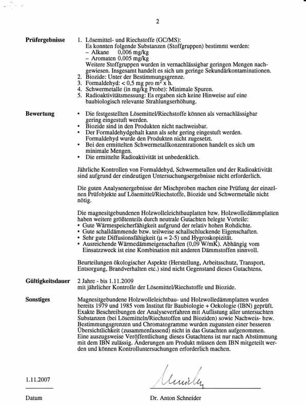
135 135
136 136
137 137
138 138
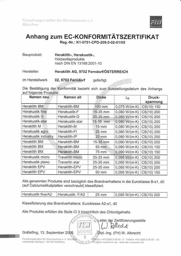
139 139