User Manual. Formwork System.
|
|
|
- Annice Phillips
- 5 years ago
- Views:
Transcription
1 User Manual Formwork System
2 Content Square column system...3 Specs & Capability...4 How to set up...5 Clamps...7 Pour rate & Safe filling height...09 Circular column system...11 Detail design and drawing...12 Specs & Capability...13 Lab study performance chart...15 How to set up...16 Beam clamp system...20 How to set up...21 Elevator shaft formwork system...22 Specs & Capability...24 Components introduction...26 How to set up...30 Maintenance and storage
3 Square column system Introduction Square Circle Formwork manufactures and supplies a range of formwork solutions which are designed to reduce construction cost, waste and labor on a wide range of construction projects. The column formwork panels are custom designed and manufactured specifically for any sized concrete columns with either polypropylene or film faced panels with LVL beams. These are then able to be clamped with formwork steel clamps for a precise waste free concrete column. The column panels from Square Circle formwork arrive with 16mm thick panels assembled with 40mm*50mm LVL beams which can meet any height column required. Square Circle Formwork also manufactures adjustable clamps made of galvanized forged steel (ASTM 50/Q345B) to be paired with our column panel formwork. 3
4 Specs & Capability LVL beam Plastic plywood Clamp Specs and material 50mm*40mm(2in*1.5in) phenolic poplar 16mm(5/8in) thickness phenolic poplar plywood laminated with polypropylene plastic sheet. Galvanized forged steel (ASTM 50/Q345B) Capability range Performance range Minimum(mm/inch) Maximum(mm/ft) Clamps 200mm/8inch 3050mm/10ft Column width 200mm/8inch 2440mm/8ft Column height NA 3050mm/10ft Standard clamp model Model Capable range Spec(mm) Weight Model mm to 400mm / 8in~1.3ft 80*18*5*5* KG Model mm to 600mm / 1.3ft~1.9ft 80*18*5*5* KG Model mm to 800mm / 1.6ft~2.6ft 80*18*5*5* KG Model mm to 1000mm / 2.2ft~3.2ft 100*20*9*9* KG Model mm to 1200mm / 2.9ft~3.9ft 100*20*9*9* KG Model mm to 1400mm / 3.6ft~4.5ft 100*20*9*9* KG Model mm to 1600mm / 4.2ft~5.2ft 100*20*9*9* KG Model mm to 1800mm / 4.9ft~5.9ft 100*20*9*9* KG Model mm to 2100mm / 6.2ft~6.8ft 100*20*9*9* KG Model mm to 2500mm / 7.2ft~8.2ft 100*20*9*9* KG Model mm to 3000mm / 8.2ft~9.8ft 100*20*9*9* KG Bearing strength Column panel Maximum stress allowance 35KN/m²or 65000lbs/ft² Theoretical maximum stress in pouring 25KN/m²or 46450lbs/ft² Clamp (All models ) Maximum stress allowance:345mpa 1 ft=304.8mm 1 inch=25.4mm 4

5 How to Assemble? For columns which are below 3.05m in height, the panels come in 4 pieces which are assembled by joining the corners with the joint designed to prevent any concrete leakage, please refer to diagram A. Apply a release agent before assembly and place any spacer (5mm-10mm thickness) in the bottom for easier dismantling after the concrete has set. Diagram A 5

6 For columns which are above 3.05m in height, they will require a staggered stacking method to achieve the height required, please refer to diagram B and C below. A set of clamps should be fastened on the bond of two stacking panel. Diagram B 6
7 Clamps The adjustable clamps come with a U-head hooking system which attach to each other when assembled and tightened with ranking holes with inserted wedge pins. Fasten from bottom to top according to clamp installation guidance chart and dismantle from bottom to top after all procedure. 7

8 Once the column has been assembled, check if all the components are fastened and pour as required. Diagram C 8
9 Pour rate & safe filling height Column area X (m²) Column height (mm) Bearing capacity (MPa) Safe filling height (mtrs) (Under 3.0mtrs vertically/hr) Pouring times X One pour 1 X One pour 3 X One pour X One pour 1 X One pour 3 X Two pour X Two pour 1 X Two pour 3 X Two pour Caution: 1. Figures are tested with clamps from Square Circle Formwork and strictly operated under user manual. 2. For assuring the reuse of the formwork panels and safety, please try filling concrete under the limit of the safe filling height. 3. Second pour should be awaited 30~60mins after first pour. 3. Column Area X(m²)= width+0.016(mtrs) length(mtrs) 9
10 Clamp installation guidance chart Clamp spacing Clamp spacing Fist level of Column Size (Column Height (Column Height clamps spacing to 3050mm/10ft) 3050mm/10ft) the ground 500*500mm 400mm 350mm 150mm 600*600mm 400mm 350mm 150mm 700*700mm 400mm 350mm 150mm 800*800mm 400mm 350mm 150mm 900*900mm 350mm 300mm 150mm 1000*1000mm 300mm 280mm 100mm 1100*1100mm 300mm 280mm 100mm 1200*1200mm 280mm 250mm 100mm 1300*1300mm 250mm 200mm 80mm 1400*1400mm 250mm 200mm 80mm 1500*1500mm 200mm 180mm 80mm 1600*1600mm 200mm 180mm 80mm 1700*1700mm 200mm 180mm 80mm 1800*1800mm 200mm 180mm 80mm 1900*1900mm 200mm 180mm 80mm 2000*2000mm 200mm 180mm 80mm 10
11 Circular column system Introduction The wooden circular column formwork system was firstly invented and produced by Square Circle Formwork on the basis of many years experience in wood industry & construction industry, aim to replace the existing steel or fiberglass or paper. In Square Circle Formwork s view, they are either too heavy or inconvenient to install and transport, slow down your projects on installation and dismantling. Considering all those disadvantages, we now offering you a light weight, high strengthening, easier transportation and installation system, a brand new product in the market, circular column system from Square Circle Formwork made of semi-circle plywood. Layers of fine poplar sheets made into a curved shape by hot press and WBP glue with a smooth anti-water film surface. Only two half round pieces and simple accessories for your unskilled labors to build up, comes with absolute smooth finish as consequence. 11

12 Detail design and drawing 12
13 Formwork specs Inner Dia (mm) Thickness (mm) Height (mm) Component (pcs) Weight/m² (kg) 250~ ~ ~ ~ ~ Product height under 3000mm comes into 2 pieces, requiring non-stack installation method. For more information of installation detail, please refer to following How to set up section. Product strength Inner Dia Bearing Bonding Bending (mm) strength strength strength KN 1.27MPa 50MPa KN 1.36MPa Accessory specs & strength Material Width (mm) Thickness (mm) Max tensile strength (N/mm 2 ) Belt Q235 steel Bolt Gr 8.8 bolt (12*100mm) NA NA
14 Reusability & Finish grade. Reusability Class 1 finish Class1 finish Class 2 finish (without release agent) (with release agent) (with release agent) 5~8 times 2 times 3~5 times 8 times 1. Figures are statistics base on average performance of product according to experience. Pour rate & Safe filling height Inner Dia Column height Safe pour rate Safe filling height (mm) (mm) (mtrs/hour) (mm) 250~ No limit No limit 250~ No limit 3200mm 1600~2400 Any height mm 1. Second pour should be awaited 30~60mins. Belt fasten height guidance Level Belt height (mm) Level Belt height (mm) Level Belt height (mm) 1 st 50 9 th th nd th th rd th th th th th th th th th th th th th th th th th 7050 Fasten every 200mm Fasten every 300mm Fasten every 400mm 14

 Bending")
")
15 Lab study performance chart Schematic diagram (Kn/m²) Bending moment diagram(mpa) shearing force diagram (Kn) 15

16 How to set up Step1 Join the semi-circle pieces after applying release agent (release agent is recommended), and fasten the bottom with accessory belt in the target location, set a 5~10mm spacer in the bottom in advance for easier dismantle sake. Step2 Cases which column height higher than 3000mm require long-short stacking installation, all the joints need to be fastened against by an extra belt. Then fasten the whole column according to the Belt fasten guidance (chart above) 16
17 Step 3 In the case of column heights under 3000mm the components comes in two pieces, please follow step 1 and fasten the column according to the Belt fasten guidance After all the belts are fastened tight and roughly parallel, pour the concrete under the instruction of Pour rate & Safe filling height. For assuring your own safety and reuse of the product, please pour the concrete as gently as possible, and vibrate the concrete completely. How to manage a cross beam If cutting is required to adapt the beam across, please waterproof paint the exposed plywood edge after cutting for assuring the best reuse of the product, and hand craft the formwork to adapt the design, fasten the beam proper with your method or use beam clamp from Square Circle Formwork. 17
18 How to brace the reinforcement Reinforcement is necessary, if no current support system is available please use four lumbers, Recommended size 50mmx100mm and as long as required to lean them against the column, then fasten 4 steel pipe horizontally in the bottom, and repeat the method every 1000mm. 18
19 How to dismantle After the concrete is fully dry, please remove the belt from the top to the bottom and take off the panel gently, panel may come off automatically, please hold them before all the belt are removed, if not please knock the column for dismantling. (do not use a sharp end tool to lever) 19

20 Beam clamp system Introduction Beam Clamp system from Square Circle Formwork is a better improvement over the traditional of reinforcement beam formwork by a tie rod-free way on fasten tight and find support from the ground. Specs and detail material capability range weight Height max bearing strength Model.1 Q345 steel 200mm~400mm 6kg 600mm 6kN Mode.2 Q345 steel 400mm~600mm 7kg 700mm 6kN 20
21 How to set up To fasten the beam formwork, choose the right dimension beam clamp available from width 200mm to 600mm, place the fix end and bottom against to the formwork. Push the adjustable end against to the other side of the beam, plug in the wedge and fasten the clamp by knocking the wedge down by hammer. The beam clamp attach to formwork by nail on the side safe pour rate safe filling height installing gap installing gap (mtrs/hour) (mm) (beam width 400mm) (width 400mm) every 500mm every 400mm 21
22 Elevator shaft formwork system Introduction Square Circle Formwork has been a trustworthy manufacture of advanced formwork system, specializing in providing the best formwork systems to contractors world wide since 2009, serving them to achieve their goal. Our innovation engineering team understood all the difficulty in shaft construction, combined the experience from the construction field, aim to offer your project an easier practical formwork system. So here we are, more than a thousand components shaped from CNC machines assemble by mechanical arms, combines with aluminium, galvanized steel and plywood formwork, a scaffolding-free stretching elevator shaft formwork system is now released to minimize the labor-cost, reducing the danger and difficulty during shaft construction. Now elevator shaft form system from Square Circle Formwork is coming to change the way building shaft construction and achieve you a nice finish absolute vertical shaft. 22
23 System introduction 23
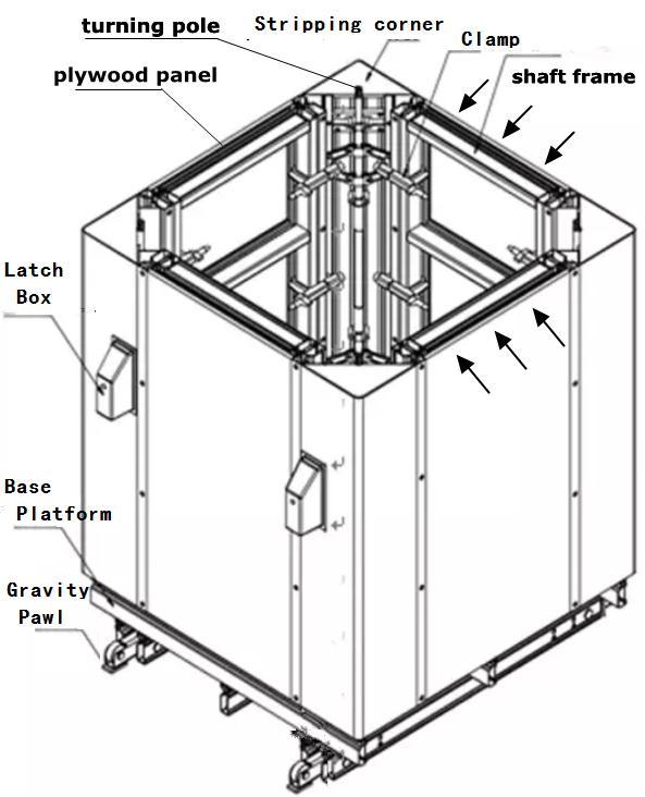
24 Components introduction 1.Elevator Shaft s Corner Quantity Material Section size(mm) Height (mm) 4pcs aluminum alloy 250*250* /2400/ Shaft Plywood Panel quantity Material Size Thickness(mm) 4pcs Plastic coated plywood customize 15 3.Elevator Shaft Frame Quantity Material Size height (mm) 4pcs Aluminum alloy customize 1600/2400/ Elevator Shaft Base Quantity Material Size 1pcs Film face plywood & aluminum alloy customize 5. Connecting Clamp Quantity 24pcs 6. Latch Box Quantity 4pcs 7.Crane hook Material Galvanized steel Material ABS plastic & tie rod All-purpose connecting part One-time use accessories Quantity Material Attach on the top of shaft 4pcs Galvanized steel frame for crane lifting. 24
25 Specs & strength Components name Weight Max bearing pressure Shaft corner 46kg/79kg/84kg 50.9KN/m² Shaft panel 25kg/m² 50.9KN/m² Shaft plywood 9kg/m² 50.9KN/m² Shaft platform 30kg/m² 40KN Connecting clamp 2kg 10KN Crane hook 2kg 10KN Gravity Pawl NA 40KN Caution:Do not place extra cargo into it for transportation purpose. 1.Safe loading limit 2 ton. 2.Actual concrete pressure during construction 24KN/m². Pour rate & safe filling height condition Using Square Circle Formwork outer form system Safe pour rate Safe filling height (m/hrs) (mm) Using hand-craft outer form Available pour height in once Available height (mm) Single installation stacking installation 25
26 Components function and operation guidance Elevator shaft s Stripping Corner The elevator shaft s stripping corner is the transmit component to assist the panel strip off from the concrete. Wrench the turning pole on the top running the slider connect with the aluminum structure to achieve the expansion and shrinking. Transmission part is attached and protected by the electrophoretic aluminum alloy shell which is smooth enough and not sticky to the concrete. Elevator shaft base platform Instead of scaffolding, the shaft base is support by the 4 gravity pawl below the platform sitting on the pre-embeded hole. It provides an operating platform for labors to adjust the inner shaft formwork system into a exact opposite position to the ground floor by laser gradienter in four corner, make sure the shaft construction is accurate and straight. Elevator shaft frame & panel The frames are customized to the right size according to demand, also the plywood panels. Both are changeable adapted to the shaft s corner to achieve different size of elevator shaft 26
27 Latch box installation The Latch box need to be pre-embeded on the concrete wall for the platform sitting steady in the shaft for further construction. The Latch box should be attached on the plat form before each pour. 1.Panel A nailed on a predetermined position for positioning. 2.Drill a 16mm diameter hole on the panel. 3.Let screw D with dia. 14mm insert into latch box for connection. 4.Make sure the 14mm plug C already insert inside the latch box. 5.Place the plug box on the anchor point, use the nut E to fix it. 27

28 Connecting clamp Aluminum clamps are used to connect the aluminum frame panel and the shaft s corner, connecting all the components into a system. 1. Loose the nut to achieve wider gap and place it between the shaft s corner and the frame panel. 2. Clamp them and spin the nut to fasten them tight. 28

29 Elevator shaft system cover The cover is made of plywood panel attached to an aluminum frame by screws, the purpose of the cover is to prevent concrete or other objects fall into the elevator shaft that might harm the labors and the equipment. 1. Cover the system on top in any case of pouring concrete or labors inside while transportation is running above. 29

30 How to build up Step1. Install the shaft base platform Place the shaft base in the right position, the base has four pawl to support the whole elevator shaft system, which are inserted into the concrete wall. Therefore, four stand reserving holes should be pre-embeded on the finish wall at the guidance place. In order to protect the reinforcement inside the concrete wall and make sure the platform are at level, the holes should be made referring to the shop drawings and the tolerance for the size of the holes should only be up to 2mm in vertical and horizontal section. 30

31 Step2. Internal Works Let the elevator shaft formwork s pawls stand on the pre-embeded holes, make sure the working platform is leveled and straight to the target position, install the shaft frame /stripping corner,then use the wrench to expand the shaft s panels. Step3. Installation of outer form and tie rods 31


32 The internal panel screw holes should be pre-drilled, before installing the external panel. Let the tie-rod with sleeves place between the internal and external panel. The distance between the external and internal wall panel should match the shop drawing. The tie-rod should not has space for leakage, the sleeves cannot insert through the internal panel. Build up outer form Step4. 32

33 Pouring Concrete Await until the external panel is fixed, check whether there is leakage or if there are any nuts that are not tighten, if everything is clear, concrete need to be pour by using the vibrating sticks. While vibrating the concrete, the vibrator should not damage the panels, sleeves, wall screws, the latch boxes and all other elevator shaft formwork accessories. Step5. Panel Strip Off 33

34 Once the concrete has formed, loosen the nuts, dismantle down the external panel clamps, and take out all the wall screws, use the wrench to adjust the panel to contract the panel and lift out the whole elevator shaft formwork. Once the concrete has reached the required strength, the panel needs to be stripped off as earliest as possible. Remove outer form and tie rods Step6. Lifting 34


35 By using the crane to lift up the elevator shaft formwork system to the other level and place the pawls on the reserved holes on the concrete wall on the next level. After leveling, again use the wrench to expand the panel and make the panel grip to the concrete wall and continue to pour the concrete as above guidance. Spin the turning pole to shrink the shaft panel Lift up by crane 35
36 Maintenance & Storage 1. Please store the product in dry clean indoor environment while not using, exposing the product to the climate may lead rust, scaling and damaged. 2. For assuring better finish and easier dismantle, please apply release agent on column panel before assembling and pouring. 3.For assuring better durability, please don t drop them from high and clean the product every time after using,with wooden tools. 4. After cutting the form, please paint the exposed edge with water-proof painting. 5. Assuring the best efficiency of the steel made accessory, clean up all the concrete occasionally pour on the accessories as soon as possible. Forming Concrete Easily 36