Building Construction
|
|
|
- Johnathan Richards
- 5 years ago
- Views:
Transcription

1 Building Construction Shallow Foundations Module-III
2 Introduction The foundation can be classified broadly into two types: Shallow foundations Deep foundations
3 Shallow foundations
4 Shallow Foundations When the depth of foundation is less then or equal to the width of foundation, then it is termed as shallow foundation. It is also known as open foundation. A shallow foundation is placed immediately below the lowest part of the superstructure. A footing is a foundation unit constructed in brick work, stone masonry or concrete below the base of the wall or column for the purpose of distributing the structural-load over wide area.
5 Types The shallow foundation can be classified into following types: Spread footing Combined footing Strap footing Mat or Raft foundation
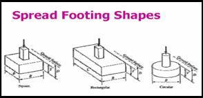
6 Spread Footing Spread Footing:- Spread footings are those which spread the super-imposed load of wall or column over larger area. Spread footing support either column or wall It may of following kinds Single footing for column Stepped footing for a column Sloped footing for a column Wall footing without step Grillage foundation

7 Spread Footing

8 Spread Footing
9 Single Footing for a Column A spread footing for a single column is either known as the isolated footing or pad footing. In this case, the footing may consist of simple concrete block projecting out from the column face on all sides. The base dimensions of the concrete base should not be less than twice the appropriate lateral dimensions of the column in that direction. The thickness of concrete block should at least be equal to side offset from the column face.
10 Stepped Footing for a Column If the column load is more or if the safe bearing pressure of the soil is less, the base area will be large. In such a case, it is necessary to provide masonry offsets, to achieve larger spread, before the load is transferred to the concrete base. The height and width of each offset should be so proportioned that the rate of spread does not exceed the permissible value for the masonry.
11 Slopped Footing for a Column These are also known as Isolated or Individual column footings. They have the projections in the concrete base. Due to the low bending strength, the footing constructed with brick, stone or plain concrete require considerable depth to be safe to carry heavy loads. The depth of plain concrete footing can be reduced much, by providing reinforcements at its base to take-up tensile stresses. RCC column footings may be circular, rectangular, or square in plan. The footing is reinforced both-ways by means of mild-steel ribbed bars placed at right angles to one another at equal distance apart.
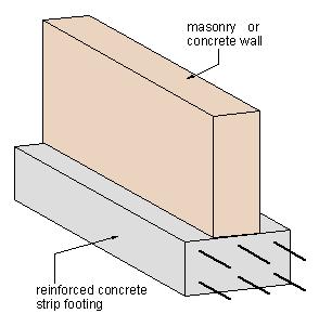
12 Wall footing without step (Strip footing) It is also called strip footing, which provides a continuous longitudinal bearing. Thus, a spread footing for a continuous wall is called a strip footing When the wall carries light loads and the safe bearing pressure is very high, width of the footing may be very small. In such a case, the wall directly rests on the concrete base and no masonry offsets are provided. As a rule, the width of concrete base should not be less than twice the width of the wall and the thickness should be at least equal to offset.
13 Stepped Footing for Wall When the wall carries heavy loads and the safe bearing pressure of the soil is not high, the base width required may be much greater. In such a case, the masonry offsets are provided to achieve larger spread, before the load is transferred to concrete base. In case of typical wall footing, the lowest course of bricks will have twice the width of the wall above the plinth level. The base width of the wall is achieved by providing 5 cm offset on both side of the wall. The depth of each course may be 10 to 20 cm. The depth of concrete bed is normally not less than 15 cm. and its projection on both side of wall base may be 10 to 15 cm. In any case, the depth of concrete bed should not be less than its projection beyond the wall base. Thus, in case of typical wall footings, if the walls having thickness t cm, the foundation width is equal to ( 2t + 30) cm. and the depth of foundation or approximately equal to 3t cm.
14 Grillage Foundation A grillage foundation is an isolated footing generally provided, when heavy structural loads from columns, piers or steel stanchions are required to be transferred to a soil having poor or low bearing capacity. This type of foundation is lighter and more economical, for which deep excavation is not required and provides more area at the base; so that intensity of pressure can be reduced within safe bearing capacity of soil. It can be broadly divided into two categories, depending upon the material used: (a) Steel grillage foundation (b) Timber grillage foundation
15 Steel Grillage Foundation Steel grillage foundation consists of steel joists or beams (Rolled Steel Joists-RSJ) which are provided in single or double tiers. In case of double tier grillage, the top tier is laid at right angles to the bottom tier. The beams of each tier are held in position by 20 mm dia spacer bars with 25 mm. dia-pipe separators. The grillage beams are embedded in concrete. A minimum clearance of 8 cm is kept between the beams, so that concrete can be poured easily and compacted properly. However, the distance between flanges width; so that filled concrete acts monolithically with the beams. A minimum cover of 10 cm is kept on the outer sides of the external beams as well as above the upper flanges of the top tier. The depth of concrete below the lower tier should be at least 15 cm.

16 Steel Grillage Foundation
17 Method of Construction The excavation for foundation is done to the desired depth and the bed is well leveled. The foundation bed is then covered with a 15 cm. thick rich mix of concrete, which is well compacted to make it impervious. The grillage beams are then placed on this bed at specified distance using separators. The top surface of grillage beams is kept in a horizontal plane and rich cement grout is filled all around the lower flanges of the beams to secure them to the concrete bed. The concrete is then placed between and around the beams. The second tier of beams is then placed at right angles to the first tier and the entire space is filled with concrete. The steel stanchion is then erected on the base plate fixed on the second tier beams; with the help of side angles and gusset plates. These connecting elements are also embedded in the concrete so that the joint becomes rigid.
18 Timber Grillage Foundation This type of foundation is provided for heavily loaded masonry wall or timber columns. This foundation is specially useful in waterlogged areas, where the bearing capacity of soil and is very low and where the steel beams may get corroded due to subsoil water, the loading on the soil is limited to 50 to 60 KN/ m 2. The foundation uses timber planks and timber beams in place of steel joists. No concrete is embedded between the timber joists. However, the bottom concrete provided in steel grillage foundation is replaced by timber platform constructed of timber planks.
19 Combined Footing A combined footing is a single footing, which supports two columns. A combined footing is provided under the following circumstances: When the columns are very near to each other, so that their footing overlap. When the bearing capacity of soil is less, requiring more area under individual footing. When the end column is near a property line so that its footing cannot spread in that direction. A combined footing may be rectangular or trapezoidal in plan. The aim of combined footing is to get uniform pressure distribution under the footing. For this, the Centre of gravity (CG) of the footing area should coincide with the C.G. of the combined loads of the two columns. If the outer column, near the property line, carries heavier load, provision of Trapezoidal column becomes essential to bring the C.G. of footing in line with the C.G. of two column loads.
20 Combined Footing
21 Strap Footing A strap footing consists of two or more footing of individual columns, connected by a beam, called a strap. When a column is near or right next to adjacent property limit, a square or rectangular footing concentrically located under the column would extended into the adjoining property, which may not be permissible. In that case, the strap footing may be provided. The strap beam, connecting the spread footing of the two columns, does not remain in contact with soil and thus does not transfer any pressure to the soil. The function of the strap beam is to transfer the load of heavily loaded outer column to the inner one. In doing so, the strap beam is subjected to bending moment and shear-force and it should be designed to withstand these.

22 Strap Footing
23 Raft Foundation A Raft or mat is a combined footing, which covers the entire area below the whole building or structure and supports all the wall and columns. When the allowable soil pressure is low or the building loads are heavy, the use of spread footings would cover more than one-half of the area and it may prove more economical to use mat or raft foundation. They are also used, where the soil mass contains compressible lenses or the soil is sufficiently erratic so that the differential settlement would be difficult to control. The mat or raft tends to bridge over the erratic deposits and eliminates the differential settlement. A raft foundation is also needed to reduce settlement on highly compressible soils, by making the weight of the structure and raft approximately equal to the weight of the soil excavated. Raft foundation consists of thick reinforced concrete slab covering the entire area of the bottom of the building or structure like a floor. The slab is reinforced with bars running at right angles to each other both near the bottom and top face of the slab. Sometimes, it is necessary to carry the excessive column load by an arrangement of inverted main beams and secondary beams, cast monolithically with the raft slab.

24 Raft Foundation
25 Foundations in Black Cotton Soils Construction of buildings on black cotton soil or expansive soils is very much dangerous due to its volumetric changes with the change of atmospheric conditions When the black cotton soil becomes wet, it will swell excessively and when becomes dry, it will shrink excessively. Thus, the black cotton soil is highly sensitive to water. Due to the presence of fine clay particles, the black cotton soil will swell, when it comes in contact with water. The differential settlement of the building, caused by the movement of the ground due to the alternate swelling and shrinkage, results in formation of cracks. The cracks thus formed are sometimes 15 to 20 cm wide and 2.5 to 4.0 cm deep.
26 Precautions for foundations in black cotton soils The various precautions are taken during foundation construction in black cotton soils: The foundation should be taken to such a depths, where the cracks cease to extend. The minimum depth of foundation should be at least 1.50 m. If the depth of black cotton soil does not exceed 1.5 m, the entire layer of black cotton soil may be removed and the foundations should be laid on hard bed. The foundation concrete or masonry work should not be in direct contact with the black cotton soil. This can be done by making wider and deeper trenches for foundation and filling the sand or moorum on either sides and below the foundation. The bed of the foundation trench should be made firm or hard by ramming it well and 30 cm. layer of moorum should be spread in 15 cm. layer over it, which is well watered and rammed and then foundation concrete should be provided. The construction in black cotton soil should be carried out during dry season. The external walls should be provided with plinth protection at ground level, so that moisture does not enter in foundation during monsoon.
27 Type of Foundation in Black Cotton soils Strip foundation: The strip foundation for walls and the pad foundation for columns may be provided for medium loads. When the soil is expansive and having little swelling pressure, a 60 cm. thick layer of cohesion less soil is provided below the foundation concrete and around the footing and also below the flooring. When the soil swells, the sand layer would expand, but there will be no discontinuity in the soil support. Where the swelling pressures are relatively high the alternative layers of moorum and sand are provided, which acts as a spring and can compress or expand along with the sub-soil movements. When the soil is soft and having poor bearing capacity, a 30 cm thick layer of ballasts and moorum should be provided and rammed and then 30 cm thick layer of coarse sand may be placed.
28 Strip foundation
29 Pier Foundation For the walls carrying heavy loads, the pier foundation with arches may be provided. The piers are dug at regular interval and filled with concrete, which are connected by concrete or masonry arch and the wall may be constructed over it. The arches are constructed with a gap above the ground level which may permit the movement of soil during swelling and shrinkage.
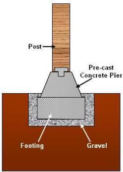
30 Pier Foundation
31 Under-Reamed Pile Foundation The pile foundation are provided in expansive soils such as black cotton soil, filled up ground and soils having poor bearing capacity. Under-reamed pile are bored cast-in-situ concrete piles of shallow depth (1 to 6m) having bulb shaped enlargement near the base. In this type of foundation, the structure is anchored to the ground at depth, where ground movement due to change in moisture content is negligible. The piles are connected by a rigid capping beam, suitably reinforced, over which the wall is constructed.

32 Under-Reamed Pile Foundation
33 Causes of Failure of Foundations Unequal settlement in subsoil: Unequal settlement of foundation may lead to cracks in the structural components, which results into the failure of the structure. The unequal settlement of foundation may be due to reasons such as; The nature of the soil may not be uniform over the entire site of the building. The loading conditions may not be uniform. The pressure on the soil may exceeds the safe-bearing capacity of the soil.

34 Unequal settlement in subsoil
35 Causes of Failure of Foundations The various remedial measures are taken to prevent unequal settlement of sub-soil The nature of soil and loading conditions should be uniform over the entire site of the building. The pressure on the soil should not exceed the safe bearing capacity of soil. Material used in construction should be durable, so as to avoid danger of disintegration of the foundations. As far as possible, eccentric loading should be avoided.
36 Unequal Settlement of Masonry The mortar used in the masonry may shrink or compress, when excessive load comes over it before setting, which results into unequal settlement, which results into unequal settlement of masonry. The various measures adopted are as follows: The mortar should provide easy workability and should not be too lean or too stiff. The masonry should be constructed to the same level throughout the building. The height of masonry should not be more then 1.5 m /day The curing of masonry should be done properly for at least 10 days.

37 Unequal Settlement of Masonry
38 Horizontal movement of soil adjoining the structure The clayey and black cotton soil undergo volumetric changes with the changes in atmospheric conditions. They swell excessively when wet and shrink excessively when dry, due to which the cracks are formed in the structure. The various precautions taken are as follows; The load on the the foundation should be limited. Foundation should be taken to a depth where the cracks ceases to extend. The foundation concrete block or masonry should be provided with a layer of sand or moorum on either side or at bottom to prevent the intimate contact of soil.

39 Horizontal movement of soil adjoining the structure
40 Shrinkage due to withdrawal of moisture from soil below the foundations The root of trees grown near the wall foundation, absorbs the sub soil moisture, resulting in differential shrinkage below the foundation and forms the cracks in foundation. The remedial measure taken are as follows: The safe distance should be maintained between the trees and the foundations, to avoid the damage due to the trees. The foundation of the structure should be taken to depth of at least 90 cm, to minimize the cracking action.

41 Shrinkage due to withdrawal of moisture from soil below the foundations
42 Lateral Pressure on the Walls The walls of the buildings may be subjected to lateral pressure due to sloped roof or an arch pressure or due to a violent storm or a wide cantilever projection; which may overturn the structure. In such cases, the wall foundations should be so designed that the necessary stability against lateral pressure can be achieved.
43 Lateral Pressure on the Walls
44 Action of Atmosphere The salts in the rainwater entering into the ground, may react chemically with the material of foundation and disintegrate it. Also, if the foundation is not taken to a sufficient depth, the rainwater may scour the soil and expose the foundation. Due to the changes in the sub-soil water table, the expansion or shrinkage of the soil may takes place, which causes the cracks in the foundation.
45 Action of Atmosphere The various precautions are as follows: The foundations should be taken to sufficient depth to avoid the adverse effect of atmosphere. The adequate drainage provisions of sub-soil water should be made by providing proper ground slope. The foundation should be provided with dense cement concrete or stone masonry, where the ground water and soil contains excessive salts. The sides of the foundation trenches should be well filled and consolidated and providing plinth protection all along the external wall to keep the rainwater away from the building.
46 Lateral movement of soil below foundation: When the building is situated near the river bank or deep excavation is done very near to the building; the soft or loose soil below the foundation may be disturbed and causes dangerous position for building. In such situations the sheet piles of timber or steel, should be driven to prevent the lateral or escape of the soil.

47 Lateral movement of soil below foundation
48 Setting Out Foundation Trenches The setting out foundation trenches means the marking of the excavation lines and centerlines, etc. on the ground before excavation is started. The setting out plan or foundation layout plan is a dimensioned ground floor plan usually drawn to scale of 1:50. For setting out the foundations of any building, the centerlines of the longest outer wall of the building is first marked on the ground by stretching a string between wooden pegs driven at ends. This serves as the reference line for marking the centre lines of all the walls of the buildings. The centreline of the wall, which is perpendicular to the long wall, is marked by setting up a right angle. The right angle is set up by forming triangles with sides 3, 4 and 5 units long. If we fix the two sides of right angled triangle to be 3 m and 4 m then the third side i.e. hypotenuse should be taken as 5 m. The dimensions should be setout with a steel tape.
49 Setting Out Foundation Trenches Similarly, the outlines of the foundation trench of each cross-wall can be set out, which are marked by stretching the string joining the corresponding pegs at the two extremities of the line, with the help of dry line powder. In an accurate method, the centerlines of the building wall are carefully laid by means of small nails fixed on the top of the wooden pegs driven in the brick pillars or platforms constructed at both ends of each wall. The platforms are about 20 cm. thick and 15 cm. wider than the trench width and are plastered at the top. The top of platforms should be equal to plinth height of the building.

50 Setting Out Foundation Trenches
51 Questions What are the causes of failure of foundation? Mention remedial measure. When do you suggest: Combined footing Strap footing Raft foundation Mention foundation suitable for black cotton soil?
52 Thanks