I-65 over the Wildcat Creek Emergency Repair Anne Rearick Bridge Director, INDOT Jeremy Hunter Bridge Design Manager, INDOT March 8, 2016.
|
|
|
- Amanda Constance Foster
- 5 years ago
- Views:
Transcription
1 I-65 over the Wildcat Creek Emergency Repair Anne Rearick Bridge Director, INDOT Jeremy Hunter Bridge Design Manager, INDOT March 8, 2016 Event Date

2 Background Bridge was built in ,000 AADT 5 spans 67-6, 85, 85, 85, 67-6

3 Background Piers are founded on spread footings Artesian conditions present


4 Background The bridge was undergoing a deck replacement and widening Piles had been driven at Bent 1, Pier 2 and Pier 3
 Sand w/artesian Features Spread")
5 Background H-Piles Pier 3 Coffer Dam Sand and Gravel Impermeable Layer (Loam) Sand w/artesian Features Spread Footer Rock
6 Timeline August 3 rd Pier 3 production piles completed August 4 th Cofferdam dewatered August 4 th Bridge closed after bearings fell out at Pier 3 August 5 th Bridge re-opened after jacking and temporary grillage installed August 6 th Cofferdam dewatered
7 Timeline August 7 th Bridge closed August 14 th Micropile solution chosen August 18 th Purdue installs monitoring system August 19 th Test pile installation begun September 2 nd Concrete Mix and Thermal Control Plan Approved and Thrust Block Poured
8 Timeline September 2 nd Jacking procedure approved September 5 th Required Concrete Strength reached and Jacking operations completed September 6 th Bridge Inspection and Load Tests Completed September 6 th Bridge re-opened


9 Cofferdam


10 Timeline Bridge Closed August 7, 2016

11 Why was the Bridge Closed? It was observed Aug 7 th that Pier 3 was sinking

12 Why was the Bridge Closed? 10 down on the East, 9 down on the West and rotated 7 uniformly to the north
13 Why was the Bridge Closed? Photo Courtesy Bob Fisher, Parsons
14 Plan to address the Pier Perform Additional CPT and SPT borings Develop a remediation plan that provides for a 30 year bridge life, assures the stability of the pier and safe construction activities for both NB and SB Pier 3 Develop a monitoring plan
15 Options Considered Compaction grouting Pressure grouting Micropiles Drilled shafts Load Testing Or a combination of all of the above
16 Potential Repair Solutions Pressure Grouting Concept: Pump flowing grout into artesian layer to densify the material and stabilize subsurface under the spread footing Foundation Underpinning Concept: Substitute a deep foundation for the failed spread footing
17 Proposed Repair Solution Foundation Underpinning Micropiles Core holes through existing spread footing Install casing through holes Install reinforcing bar Pressure grout through the casing

18 Micropile Conceptual Drawing
19 Structural Connection


20 Test Pile Installation Photos Courtesy Bob Fisher, Parsons

21 Micropile Installation Photo Courtesy Bob Fisher, Parsons

22 Transfer Block


23 Transfer Block Photos Courtesy Bob Fisher, Parsons

24 Transfer Block Photo Courtesy Keith Hoernshemeyer, FHWA
25 Thermal Control Plan Temperature sensors installed 35 degree temperature limit Max 115 degrees PVC cooling pipes installed to draw water from the creek if necessary Insulation Blanket


26 Thermal Control Plan Sensor Control Locations

27 Pile Cap

28 Pile Cap

29 Pile Cap


30 Thermal Control Plan Photos Courtesy Bob Fisher, Parsons

31 Jacking Photo Courtesy Bob Fisher, Parsons

32 Post Jacking Photo Courtesy Bob Fisher, Parsons

33 Temporary Support Photo Courtesy Bob Fisher, Parsons
34 Opening Requirements Full Hands on Fracture Critical Inspection Load Tests to be done 24 hours following the re-establishment of final elevations Acceptable analysis of leaving the tilt in the pier 3500 psi in the transfer block
35 Proof Testing Monitoring Bridge Inspectors in place to monitor the pile cap and the superstructure for movement Purdue Sensors Inclinometers on pier cap to measure lateral movement Strain Gages on the bottom flange adjacent to the pier to indicate vertical movement 3D Automated Survey System
36 Proof Testing Tests Vertical Load Trucks Beside Each Other Negative Moment on Superstructure Trucks front to back with gap Longitudinal Force Single truck braking from highway speed to a stop Eccentric Load on Pier Foundation Single truck along outside shoulder


37 Load Test Braking Test Following Test Static Load Test Following Test Photo and video Courtesy Bob Fisher, Parsons
38 Load Test Trucks Beside Each Other Max Vertical Load Trucks front to back Negative Moment on Superstructure Single Truck Braking from Highway Speed to a stop Single truck along outside shoulder eccentric load on pier and foundation

39 Bridge Re-opened September 6, 2016
40 What happens next? A plan is being developed that will address the construction at the remaining piers such that another foundation settling event will be not be initiated. Bridge monitoring system will be place for the remainder of the construction
41 Thank you to: FHWA Parsons Purdue University RQAW ATC Walsh/CHA/SME Design Build Team
42 I-65 Wildcat Creek Bridge Artesian - Geotechnical/Structural Mir A. Zaheer, P.E., Geotechnical Design Engineer, INDOT March 08, 2016

43 I-65 Wildcat Creek NB Bridge
44 Objective Improve understanding of foundation design and construction. Improve understanding of geotechnical investigations, designs, plans and specifications. Improve understanding of artesian conditions.
45 Outline Foundation Issues - I-65 over Wildcat Creek, Tippecanoe County What Happened How Was it Investigated What Were the Findings What Was the Solution How Can These Problems Be Avoided in the Future
46 Outline Foundation Issues - I-65 over Wildcat Creek, Tippecanoe County What Happened How Was it Investigated What Were the Findings What Was the Solution How Can These Problems Be Avoided in the Future
47 What Happened Pier #3NB Spread Footer settled. Vertical Settlement = 10 inches Lateral Deflection = 7 inches

48 Artesian Aquifer - General

49 Pile Installation


50 Cofferdam Construction


51 Cofferdam Construction
52 Outline Foundation Issues - I-65 over Wildcat Creek, Tippecanoe County What Happened How Was it Investigated What Were the Findings What Was the Solution How Can These Problems Be Avoided in the Future
53 Investigation At INDOT s direction DB team installed Piezometer & did SPT borings and CPT soundings
54 Contract Geotechnical Report Artesian water conditions were noted at the interior piers of the Interstate 65 Bridge over Wildcat Creek. Ground water was noted flowing adjacent to the existing interior piers adjacent to Wildcat Creek. Heaving sands were encountered within the augers during sampling in Boring S5-TB-WC-2 and S5-TB-WC-5.
55 Contract Geotechnical Report Spread footings are not recommended for support of the interior piers due to the presence of artesian ground water conditions, potential differential settlements between new and existing footings, the risk of undermining the existing spread footings, causing a quick condition during construction excavations to reach the existing spread footing bearing elevations and the projected scour depth. Significant dewatering will likely need to be performed prior to excavations for the proposed interior pile caps.

56 Subsurface Profile


57 Piezometer Post Failure Pier 3

58 Piezometer Post Failure Pier 3 Piezometer installed after Failure of Pier #3 Foundations
59 Soil Profile At Pier #3 Cofferdam
60 CPT Soil Profile at Pier #3
61 Outline Foundation Issues - I-65 over Wildcat Creek, Tippecanoe County What Happened How Was it Investigated What Were the Findings What Was the Solution How Can These Problems Be Avoided in the Future
62 Findings Artesian conditions loosened soils below the existing footing causing settlement Probable Mechanism Seepage of water and piping of fine sand from beneath the loam layer around the piles and the sheet piles via preferential pathways Heaving of soil inside cofferdam, and movement of sands from underneath the footing toward the voids formerly occupied by heaved soils.
63 Findings Penetration of the of the sheet piles through the loam layers and subsequent movement of sand towards the voids created by the possible heave. Water was flowing into the cofferdam along the north side from sheet piling abutting the west end of NB pier to the pump location at the southwest corner. Top of loam layer may be below the bottom of the footing. Sands placed during the 1968 construction scoured from under the footing.
64 Findings Seepage, could occur in the case of a sandy foundation or in the case of preferential flow paths. The process of excavating, which relieves confining pressure coupled with the high gradient and driving of sheetpiles and/or piles may have fractured the confining layer that was serving as the aquitard. A combination of all of the mechanisms caused the failure.
65 Outline Foundation Issues - I-65 over Wildcat Creek, Tippecanoe County What Happened How Was it Investigated What Were the Findings What Was the Solution How Can These Problems Be Avoided in the Future
66 Solution Multiple options were investigated Compaction Grouting Drilled shafts Micropiles Micropiles were ultimately chosen as the most feasible alternate to support the existing spread footer & also the rest of the piers
67 Solution DB s Team Assessment Drilled shafts, while technically feasible, were considered uneconomical due to the difficult constructability issues associated with the deep granular soils and the high artesian water pressure. Therefore, a micropile type foundation system, was recommended for support of the interior piers.
68 Solution
69 Solution Use low mobility grout, LMG, to fill potential voids and densify loosened soils below footing Design and install micropiles to carry all the live and dead loads and the footing loads Drill with grout to minimize the impact of artesian conditions Perform Tension Load test Exclude the contribution of end bearing
70 Load Test Setup

71 Load Test Setup

72 Load Test Setup

73 Micropile Load Tests
74 Micropile Load Test TP-2 Strain Gage Loads

75 Low Mobility Grout Intakes


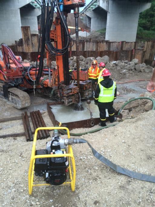
76 Micropile Installation

77 Pier #3 As Constructed

78


79 Piezometer Installation (ATC)


80 Piezometer Installation (ATC)
81 Piezometer Data At Pier 4NB
82 Piezometer Data At Pier 4NB
83 Outline Foundation Issues - I-65 over Wildcat Creek, Tippecanoe County What Happened How Was it Investigated What Were the Findings What Was the Solution How Can These Problems Be Avoided in the Future
84 Indiana Design Manual IDM Cofferdam A cofferdam is a structure consisting of. sheeting driven into the ground below the bottom of the footing elevation and braced to resist pressure. It shall be practically watertight and be capable of being dewatered.
85 Standard Specifications Standard Specifications 701 In general, they shall be carried down well below bottoms of footings, shall be well braced, and as nearly watertight as practicable. Standard Specifications 206 Cofferdams shall be constructed to protect plastic concrete against damage from a sudden rising of the stream and to prevent damage to the foundation by erosion.
86 FHWA Guidelines FHWA-NHI Pile Guidelines Use solid prestressed concrete pile, tapered piles with sufficient collapse strength or thick wall closed end pipe with flush boot plate depending upon local practice. H-piles without driving shoes may also be viable selection. Do not use mandrel driven thinwall shells, as generated hydrostatic pressure may cause shell collapse. Pile heave also common to closed-end pile.
87 Subsurface Investigations A well developed soil & groundwater profile is necessary to design a costeffective foundation. The best practice to reduce the risk of construction problems is early recognition of geotechnical problems during design stage and designing accordingly. Perform an adequate subsurface investigation in advance of final design.
88 Subsurface Investigations Should provide the following: Depth and thickness of strata (subsurface profile). In-situ field tests to determine soil design parameters. Samples to determine soil and rock design parameters. Groundwater levels including perched, regional, and any artesian conditions. Any artesian groundwater condition or other unusual groundwater condition should be identified and reported as this often has important impacts on foundation design and construction.
89 Design Considerations Check Basal stability (Piping and Heaving) and overall global stability for all stages of construction for deep excavations. Account for construction equipment loads that may increase the live load surcharge. For example; crane loads applied directly behind sheeting. Sheeting adjacent to existing spread footings shall be designed using a uniform surcharge equal to the applied footing pressure. Use appropriate sheet pile hammers, vibratory or impact, depending on soils.
90 Design Considerations Even if the structure is confirmed to be stable against uplift, the excavation scheme shall include contingency plans to address potential seepage and movement of material. The influence of pore pressure shall be confirmed using a slope stability analysis with pore pressure included. Software commonly used in the field of geotechnical engineering, has a pressure head spatial function that will linearly interpolate pore water pressure.
91 Design Considerations Given the site geology, there are two potential uplift failure modes from the artesian pressures due to excavation. The first is a mass uplift of the soil and the second is seepage via preferential pathways.
92 Design Considerations For a mass uplift failure to occur, the uplift pressure would need to overcome the cohesive resistance of the foundation. Since the preponderance of the material in the foundation is hard till overlying loose to dense sands, the calculation of factors of safety shall include cohesion. Concerns regarding uplift can be addressed by dewatering. Dewatering shall be performed to lower the water pressure beneath the confining clay layer. The water pressure beneath the confining clay layer can be reduced to a level where it is less than the total weight of the clay layer. Deep wells and/or well point systems shall be used.
93 Design Considerations Seepage via preferential pathways would not likely lead to catastrophic failure because the movement of water and possibly material would be local and could be addressed in the field.
94 Design Build Team Contractor: Designer: Geotechnical: Geotechnical: Geotechnical: Micropile: Walsh Construction CHA Consulting, Inc. SME Earth Exploration, Inc Stratigraphics Nicholson


95 Questions? THANKS
96 Understanding Performance and Service Life for Geotechnical Features Silas Nichols Principal Bridge Engineer Geotechnical Federal Highway Administration Office of Bridge Technology
97 Repair of Bridge Foundations Recent bridge foundation failures have highlighted primary demands necessary upon closing : Procedures to notify and inform public and officials i Strategies to inspect damage and assess safety and integrity of super- and substructures Expedient means for conducting investigations, remediating structure and restoring service Establishing roles and responsibilities for personnel that may be involved in solution (contract type dependent)
98 Repair of Bridge Foundations Three case histories used to illustrate primary issues: 1. I-43 over the Fox River (Leo Frigo Bridge), Green Bay WI 2. I-495 over the Christina River, Wilmington DE 3. I-65 over Wildcat Creek, West Lafayette IN


99 I-43 Leo Frigo Bridge Vitals: Built in 1980 Four lane bridge over Fox River ADT of 40, Span bridge Total length of 7,983 feet


100
101 Pile Deterioration
102 Pile Deterioration


103 Pile Deterioration


104 Repair Strategy


105 Repair Strategy


106 I-495 over Christina River Vitals: Built in 1974 Four lane bridge over Christina River ADT of 90,000 3 Main Spans; 35 Approach Spans Total length of 4,804 feet


107 I-495 over Christina River


108 I-495 over Christina River


109 Failure Mechanism


110 Failure Mechanism


111


112 Temporary Shoring Plan


113 Final Repair Plan
114 Final Repair Plan
115 Temporary Shoring


116 Drilled Shaft Construction


117 I-65N over Wildcat Creek Vitals: Built in 19?? Two lane bridge over Wildcat Creek ADT of??,000 5 Span bridge Total length of?,??? feet


118 I-65N over Wildcat Creek


119 Drilled Foundation Solution


120 Drilled Foundation Load Test
121 Lessons Learned Through review of these projects, the following was noted: While failure mechanisms were different for all three bridges, the repair methodology and approach had commonalities There is no circumstance under which a failed foundation will ever be put back into service Faster is better
122 Addressing Needs FHWA is currently working on a guidance effort based on the lessons learned: Developing strategies t for assessing initial iti safety conditions Selecting safe investigation methods Providing solution alternatives for repair Temporary shoring Permanent repair
123 Future Impact The development of guidance includes: Review of information (domestic and international) Interviews with agencies and contractors Development of protocols Identify problem and assess safety Determine cause of damage to foundation Mitigate damage to reopen structure Final report due in September 2016
124 Thank You! Silas Nichols, P.E. Principal Bridge Engineer Geotechnical FHWA Office of Bridge Technology