Add as many photos as you wish showing the bridge construction process. Especially consider photos of internal structural components that may not be
|
|
|
- Osborn Golden
- 5 years ago
- Views:
Transcription

1 Add as many photos as you wish showing the bridge construction process. Especially consider photos of internal structural components that may not be visible to judges from observing the finished bridge.
2 National Timber Bridge Design Competition College or University Name: Lawrence Technological University Student Chapter (ASCE or FPS): ASCE Address:21000 W. Ten Mile Rd. Southfield, MI Website Address: Faculty Advisor: Mena Bebawy mbebawy@ltu.edu Phone: (248) Student Member in Charge of Project: London Jocham ljocham@ltu.edu Phone: (810)
3 Team Member Class Team Member Class Team Member Class Jonathan Harden Sr. London Jocham Sr. Scott Pangburn Fr. John Leclerc Sr. Andrew Yarbrough Jr. Hours Spent on This Project Students: 60 hours Faculty: 10 hours Cost of Materials Donated: $150 Purchased: $750
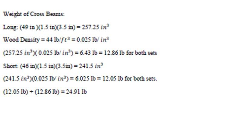
4 Abstract (Maximum 500 Word Narrative): Explain the bridge design concept and what was done to optimize stiffness wile attempting to minimize weight of the structure. The main focus on the design of the bridge were the two beams designed to be box girder beams. The design of the box girder beams was to be able to construct several different parts of the beam and fit three different pieces like a puzzle to be overlain with plywood. Another plywood sheet was added to the initial sheets to also act as a gusset plate for the plywood. The box girder opens up a lot of void space which decreases the amount of weight for the bridge. The main wood used in the structure was mostly reclaimed wood from Detroit where the architectural salvage warehouse takes the old timber from reclaimed houses in the Detroit area. Most of these boards from the reclaimed houses had some oak and other types of wood that is much stronger rather than the white pine which benefited the stiffness of the bridge. The design implements timber from torn down houses, which considers the impact on re-usability and sustainability. The installment of a carbon fiber cable also was a factor of the light weight to each beam. Stressing the carbon fiber would increase the stiffness of the beams and only adds to the weight by a small margin. The bridge deck is a simple design and is connected by longitudinal girders that run under the light weight of the bridge deck which consists of horizontal members that span from beam to beam. These longitudinal girders that run under the deck increase the stiffness of the deck due to the spreading of load across the deck rather to just one member having a large portion of the load.
5 2. Deflection Table Deflection inches 1. Loading Increment 2. Bridge 3. Beam LEFT 4. Beam RIGHT 5. Average (L & R) 6. Gross Deck 7. Net Deck 5 kn kn kn kn 0 min kn 15 min kn 30 min kn 45 min kn 60 min Loading Increments 2. Bridge As measured at midspan of the longitudinal beam receiving greatest loading. 3. Beam L As measured under the longitudinal beam to left of selected deck monitoring point. 4. Beam R As measured under the longitudinal beam to right of selected deck monitoring point. 5. Average (L & R) Average of 3 and 4, above. 6. Gross Deck As measured under the loading point expected to experience maximum deflection. 7. Net Deck Column 6 minus Column 5. Deck Span: Transverse distance between main longitudinal bridge support members measured from inside edge to inside edge = 49 in 100 =.49 in= maximum allowable net deck deflection.
6
7
8
9 4. Summary Describe Bridge and Its Behavior Under Load (max. 500 words) The bridge deck deflected as one solid unit because of the of the two 2x4 running underneath of the deck connected by a screw to each deck board. The Beams themselves did very well under loading and did not deflect a large amount, however they still deflected more than what we planned, perhaps due to constructability factors using the reclaimed wood.
10
11
12
13
14
15
16
17
18 Drawing Clearly Showing Location of Loading and Deflection Gage Points in Relation to Longitudinal Members (insert below) NOTE: Repeat slide if loading set-up was moved to measure deck deflection.
19 Drawing Clearly Showing Location of Loading and Deflection Gage Points in Relation to Transverse Members (insert below) NOTE: Repeat slide if loading set-up was moved to measure deck deflection.
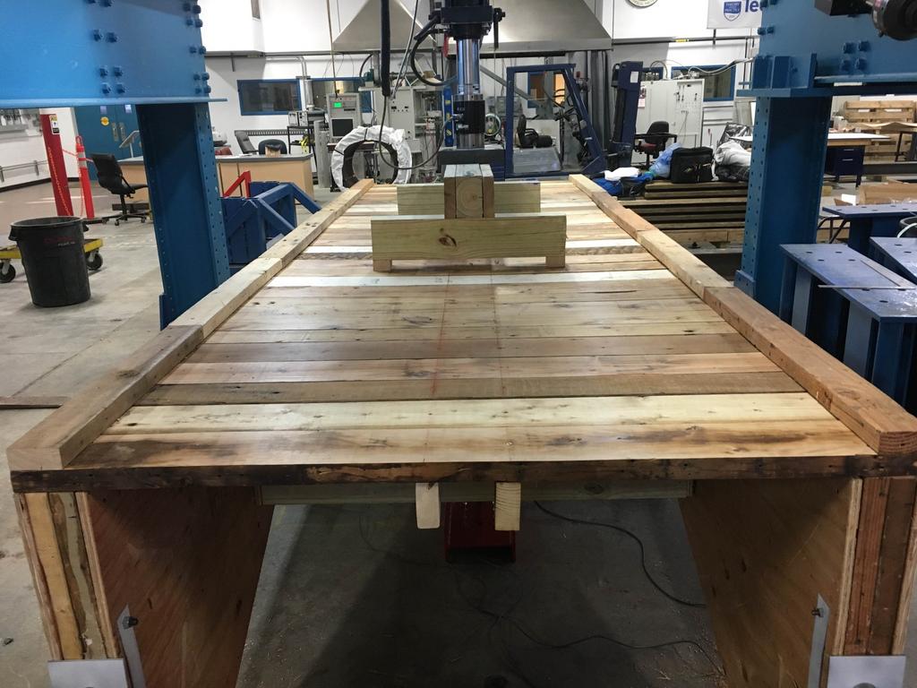
20 PHOTO Showing SIDE View of Loading Setup for Measuring Bridge Deflection (insert below) NOTE: Repeat slide if loading set-up was moved to measure deck deflection.
21 PHOTO Showing END View of Loading Setup for Measuring Bridge Deflection (insert below) NOTE: Repeat slide if loading set-up was moved to measure deck deflection.
22 End Photo of Finished Bridge

23 Side Photo of Finished Bridge

24 Trimetric Photo of Finished Bridge

25 Team Photo From left to right: Andrew Yarbrough London Jocham Jonathan Harden Scott Pangburn Not pictured: Johnathan Leclerc
26 6. Bridge Component Details Briefly describe each bridge component, as applicable. Stringers/Girders Deck Floor Beams Suspension Unique Components Box girder beam enclosed around a structural frame Reclaimed 2x6 boards with 2 2x4 lumbe running transversely along the bottom near the middle of the deck. Reclaimed 2x6 boards None Carbon fiber post tensioning through the center of the box girder beam
27 7. Preservative Treatment: Describe the preservative treatment applied to all wood members. Include type and concentrations. Also, include a short statement of why this treatment was selected. Did the treatment requirement present any special problems? If yes, provide details. If treatment was not selected, explain why. Every member was water sealant coated with Thompson water seal. This treatment was done to protect the bridge from the rain and to keep the amount of water out of the inside of the members. Another treatment was the spray-painting of the steel plates used to distribute the carbon fiber end stress on the beam. This will help with the rusting of the steel plates.
28 8. Special Considerations Indicate the End Use of Your Bridge The end use of the bridge is to be able to cross a small creek and be able to withstand the load of four wheelers and dirt bikes.
29 9. Summarize the Team s Experience from Participation in this Competition. Was it beneficial? What steps would you recommend to improve the experience? The team learned the benefits of using reclaimed wood for its strength and beauty, as well as its downfalls in terms of unreliable composition and often broken board pieces. Working together as a team the cons of using reclaimed boards was overcame to create a functional bridge. Carbon fiber use in wood construction was explored by the team as LTU generously donated it for this purpose. Though the loading used in this experiment was not enough to call for the carbon fiber, its addition to the beam improves its capacitance for to carry a higher load. Use what is available to create a bridge to suit the needs.

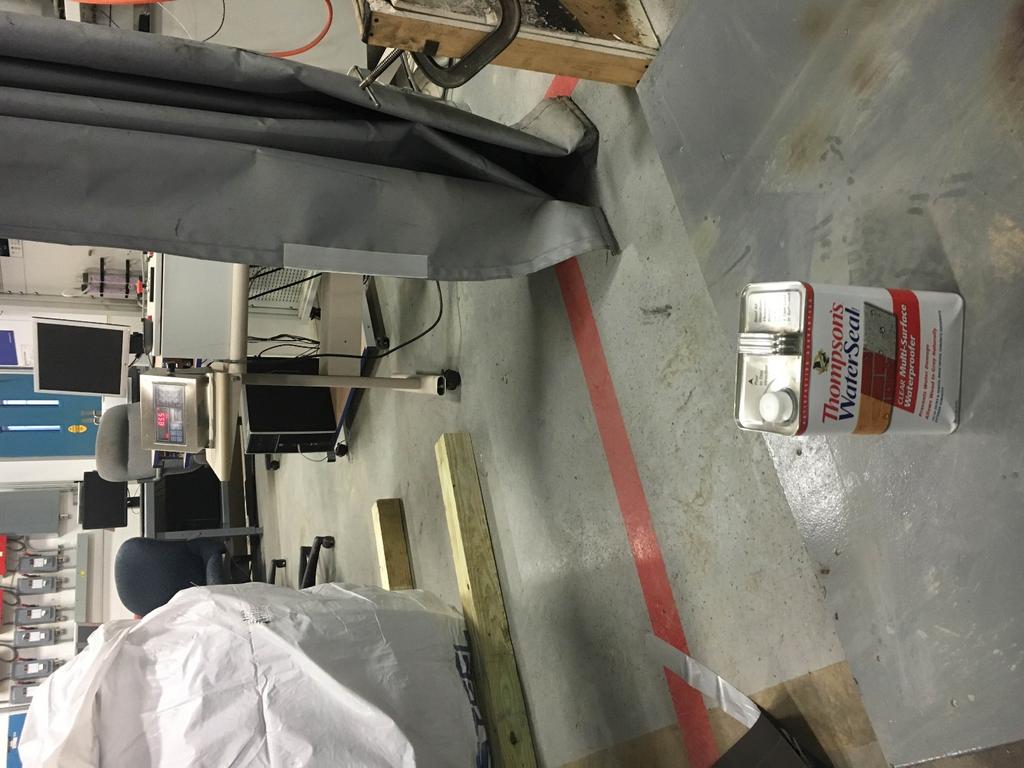
30 Photo of Bridge Weighing

31 Photo of Bridge Weighing

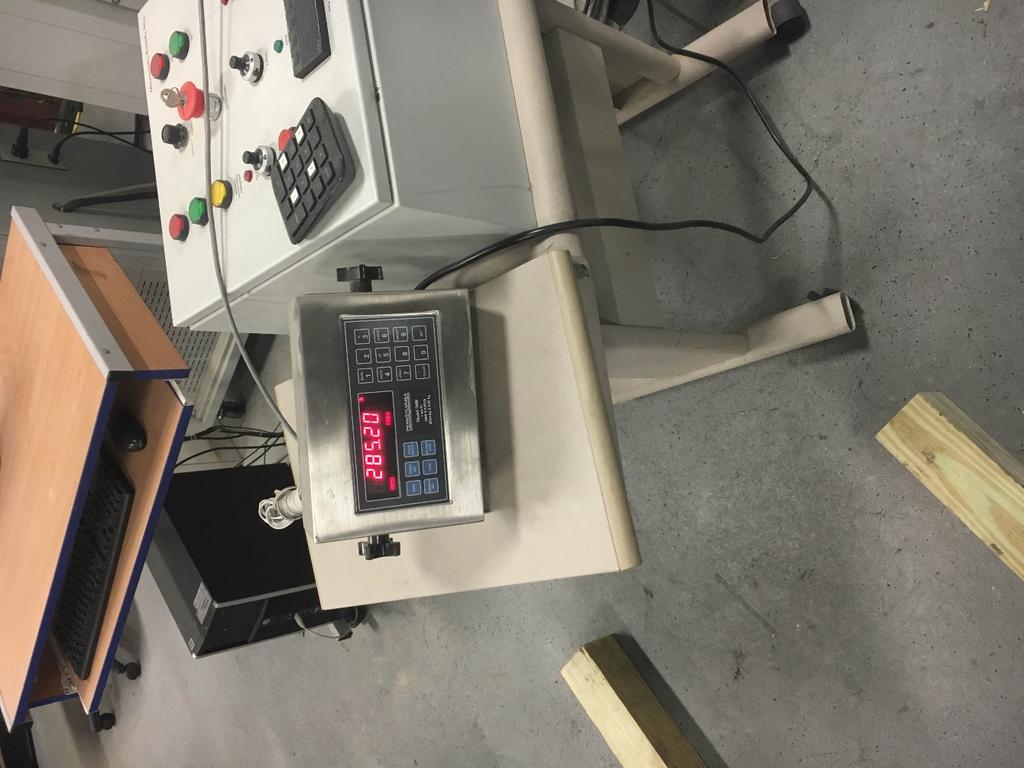
32 Photo of Bridge Weighing
 an average weighing deck")
33 Photo of Bridge Weighing Components for the bride were weighed separately. A weighted average was taken of the 2 x6 deck boards to attain a standard weight per board for the calculations (to account for variance in weight of the reclaimed wood) an average weighing deck board was selected and tested in a three point loading setup to withstand just over 1000 lbs in the center of the board.


34 One photo of each deflection gauge at full loading, with identification sign indicating DECK, BEAM LEFT, BEAM RIGHT, BRIDGE. Deck Left Beam Right Beam Bridge Support stand (only 30 mm thickeness touching the bottom of deck on each of four supports)


35 The Reclaimed deck boards were planed to reduce the height difference between them and to add to the deck s aesthetic appeal.

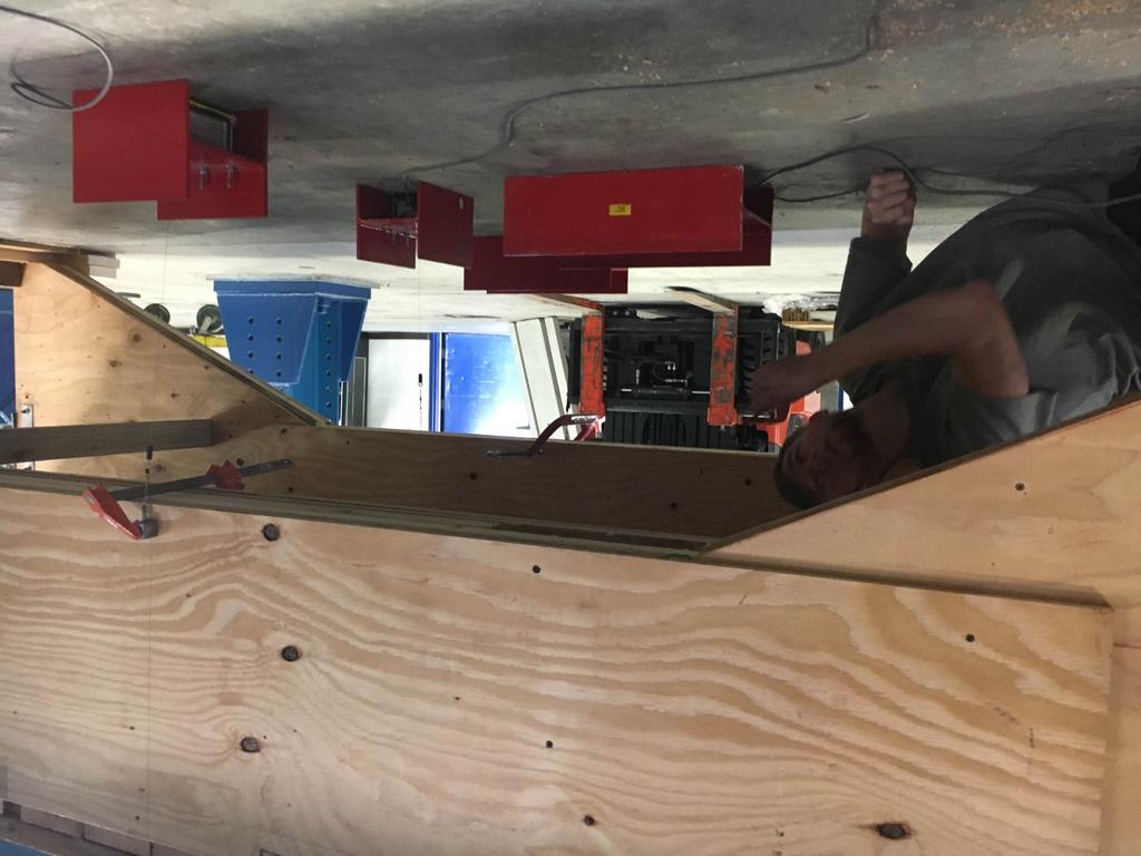
36 Add as many photos as you wish showing the bridge construction process. Especially consider photos of internal structural components that may not be visible to judges from observing the finished bridge.
37


38 Add as many photos as you wish showing the bridge construction process. Especially consider photos of internal structural components that may not be visible to judges from observing the finished bridge.

39 Add as many photos as you wish showing the bridge construction process. Especially consider photos of internal structural components that may not be visible to judges from observing the finished bridge. Carbon fiber chuck and plate assembly. The strands were post tensioned 48 hours before testing to 3000 lbs3000 lbs was chosen after a test of the strand was made using the intended chuck assembly. It held to about 6000 lbs, thus us deciding on 3000 lbs for safety.

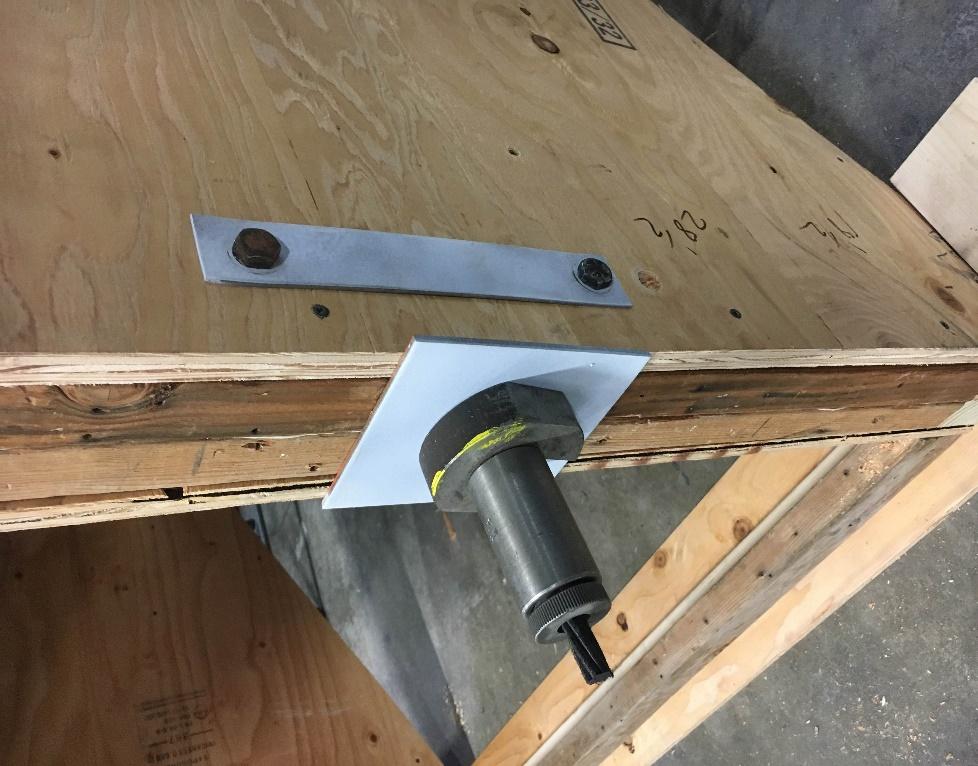
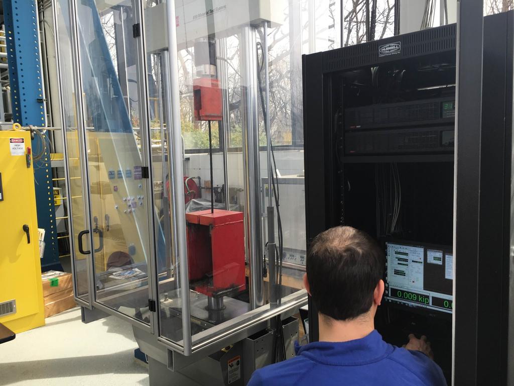
40 Strand testing and post tensioning procedure

41 Add as many photos as you wish showing the bridge construction process. Especially consider photos of internal structural components that may not be visible to judges from observing the finished bridge. Support (30 mm in thickness touching the base of the bridge)
42