Addressing Common Drilling Challenges Using Solid Expandable Tubular Technology By Larry Book, Enventure Global Technology, L.L.C.
|
|
|
- Olivia Logan
- 5 years ago
- Views:
Transcription
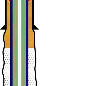
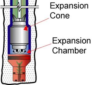
1 Addressing Common Drilling Challenges Using Solid Expandable Tubular Technology By Larry Book, Enventure Global Technology, L.L.C. Copyright 2003, This paper was prepared for presentation at the Petromin Deepwater Conference held in Kuala Lumpur, Malaysia, 21 May Abstract Maximizing hole conservation while optimizing well economics in both conventional and deepwater wells is a continual challenge. Solid expandable tubular systems address this challenge and others by applying technology that provides significant solutions. Solid expandable tubular systems have been installed in both openhole and cased-hole wellbores since November These installations occurred in a variety of well environments on land, offshore, and in deepwater to solve a myriad of drilling and completion challenges. This paper will discuss case histories in depth by describing drilling challenges surrounding the use of solid expandable tubular technology and the conditions leading to the use of this technology. Solid Expandable Tubular Systems The fundamental concept of expandable casing is cold-working steel tubulars to the required size downhole. This process, when exactingly controlled, can be mechanically preformed in a down hole environment. Many technical and operational hurdles have to be overcome when using cold-drawing processes in a downhole environment. Solid expandable systems are solid steel jointed pipe that are run in the hole as normal casing and expanded downhole to a pre-determined outside diameter (OD) and inside diameter (ID). Once the system is expanded, the entire system will withstand published collapse and yield pressures. Once the solid expandable system is put on depth, an expansion cone is used to permanently mechanically deform the pipe (Fig. 1). The cone is moved through the expandable string by a differential hydraulic pressure across the cone area, by a direct mechanical pull or push force, or by a combination of both. The differential pressure is created by pumping through an inner-string that is connected to the cone. The hydraulic force acts across the surface area of the cone forcing it upward. Mechanical force is applied by either raising or lowering the inner-string (Fig. 2). The progress of the cone through the expandable tubular string deforms the steel beyond its elastic limit into the plastic region, while keeping stresses below ultimate yield (Fig. 3). Expansions greater than 20%, based on the ID of the pipe, have been accomplished. Most applications using 4-1/4 in. to 13-3/8 in. tubulars have required expansions less than 20%. The Expansion Process A launcher at the bottom of the solid expandable tubular system houses an expansion cone and a float shoe. The launcher is constructed of thin-wall, high-strength steel that consists of a thinner wall thickness than the expandable casing (Fig. 4). The OD of the launcher can be up to the drift diameter of the previous casing or liner so it can still be tripped through the base casing. The thinner wall allows for the cone OD to be maximized. The expandable system uses an elastomer joint to both seal and anchor the system. The elastomer joint incorporates multiple elastomer sections that are bonded to the pipe using a compression
2 2 molding process. The elastomer is selected to meet the temperature requirements of the given installation. As the elastomer joint is expanded, the elastomer sections are extruded as they are cladded into the base casing. A designed compression ratio of the elastomer sections between the expanded pipe and the base casing gives the elastomer joints their sealing and load-bearing capabilities. A hanger joint is positioned at the top of the expandable liner for openhole applications and serves as both the hanger and the liner top seal. In the cased-hole installations, one elastomer joint is run immediately above the launcher and another at the top of the liner string. In this fashion, the lower elastomer joint anchors the liner at a selected depth while the upper elastomer joint completes the seal of the designated interval. Available Systems Solid expandable tubular technology has evolved over the past four years from a radical solution for drilling challenges to a logical well construction process. 1 By incorporating expandable systems in the initial well design stage, the downhole tapering effect is reduced or eliminated. Solid expandable openhole and cased-hole liners continue to be used to troubleshoot drilling problems, but expandables are also being incorporated into the well construction design. In addition to openhole liners, cased-hole liners, and expandable liner hangers, the technology also includes the following: Openhole cladding system Monodiameter system Solid Expandable Openhole Systems The openhole liner system (Fig. 5) consists of expandable casing strings planned into the well construction to minimize the telescoping effect of the original pre-expandable well designs. Solid expandables minimize well slimming while adding strings for needed depth. This slimwell application can lower mud cost by reducing the following: the annulus size reduces the amount of mud required to drill the well the amount of cuttings the size of the rig required to drill the well especially in deepwater applications The openhole system can be used as a contingency drilling liner in any well during the drilling phase. Running this drilling liner maintains hole size when an unforeseen geographical anomaly or problem is encountered. These anomalies and problems can include the following: Unstable formation Over- or under-pressured formation Loss circulation Pore pressure/frac gradient Solid Expandable Openhole Cladding System The openhole cladding system is an expandable string that is run and installed in the open hole to address the following: 2
3 3 Isolate an unstable formation Isolate a salt water flow Shut off water influx in a openhole completion The openhole cladding system installation process is similar to that of the openhole liner with the exception that it is not tied back into the base casing. Elastomers are configured to seal against the formation. The seal efficiency will be a function of the rock properties where it is set. Porosity, permeability, and rock hardness all affect the seal capabilities. Monodiameter System Monodiameter technology is currently in the final field-testing stage and already generating results that are impressive and revolutionary. This technology consecutively runs the same size expandable casing strings and expands them into each other to achieve the same ID from top to bottom. The monodiameter removes the telescoping effect of pre-expandable well design (Fig 6). Having to install an unplanned casing string because of an unforeseen geographical anomaly will no longer be detrimental to the well. The only limiting factor to achieving the target is temperature and well geometry constraints. Ultra long-reach horizontal wells will be possible where an entire field can be produced from a single drilling pad, platform, or subsea template. Wellbore extensions can be accomplished by using an existing non-producing well. A window can be cut and an expandable system could be run to re-direct the well to another target. This expandable application maintains hole size to allow a larger liner to be run into the pay zone. An example would be to cut a window in a 9-5/8 in. existing casing and run a 7-5/8 x 9-5/8 in. expandable system. Once expanded, this system would allow for a 7-5/8 in. special clearance coupling liner be run into the producing zone. Cased-hole Applications The expandable cased-hole liner system (Fig. 7) enables operators to repair existing damaged or worn casing for deeper drilling or other contingencies. The system makes it possible to upgrade exploration-grade casing to a sturdier production casing with minimal loss of casing ID. The cased-hole liner system is mechanically similar to the expandable openhole liner system except that an additional anchor-hanger joint (elastomer section) is located immediately above the launcher assembly. Expanding this system inside existing casing repairs and reinforces the larger casing for completion. The system can be used to shut off perforations in production casing for re-completion or for deepening the well. This expandable system allows for enhanced control of existing injectors and producers by shutting off unwanted gas or water production. The system has also been used to re-connect a severed wellbore due to subsidence from crust movement. Case Histories The following case histories illustrate various applications of solid expandable tubular technology in different environments. 3
4 4 Case History One: Openhole Liner Installed in the Gulf of Mexico (GoM) 2 The operator had previously drilled an ultra-deepwater well (approximately 7,800-ft water depth) that required more casing strings than anticipated. Setting successive strings higher than the prognosis called for resulted in a much smaller hole than anticipated before reaching the well s planned total depth (TD). Additional casing strings were needed to address the low drilling margins encountered, and the well was abandoned because of loss of hole size. The casing design for the second well in the prospect area included a planned 13-3/8 in. solid expandable tubular liner installation and two contingency expandable liners. The optional contingency liners consisted of 9-5/8 x 11-3/4 in. and 7-5/8 x 9-5/8 in. These expandable applications were designed into the drilling solution to give the operator an added margin for reaching TD without losing significant hole size. Two expandable liners were ultimately set in this well, making it the world s first well to have multiple openhole solid expandable tubular installations. Expandable liner systems of 13-3/8 x 16 in. and 9-5/8 x 11-3/4 in. were used. These two openhole liner installations allowed the well to be drilled to TD with optimum hole size by minimizing casing size reduction. Case History Two: Openhole Liner Installed in Asia Pacific The objective of this installation was to case off a known loss circulation zone. The expandable openhole liner was not planned in the well but was used in a contingency mode to get through the loss circulation zone. By running the expandable liner, the hole size was maintained to allow for the additional casing string to be run and still meet the production well profile at TD. The loss circulation zone was bridged with a 7-5/8 x 9-5/8 in. openhole liner. Once the approximately 1,600 ft of 7-5/8 in. liner was expanded to in., a 7-5/8 in. special clearance coupling liner was run and set to deepen the well. Case History Three: Cased-hole Liner Installed in Asia Pacific The objective of this installation was to install safely a 7-5/8 x 9-5/8 in. cased-hole liner to repair the wall-thinned 9-5/8 in. production casing. To perform this casing remediation the operator used approximately 4,500 ft of 7-5/8 in. solid expandable casing and elastomer joints that were expanded to an ID of in. This expansion ID allowed 7 in. production tubing to be run. Following the installation, the well was re-completed and put back on production. Case History Four: Cased-hole Liner Installed in Asia Pacific The objective of this installation was to install safely a 5-1/2 x 7 in. cased-hole liner to isolate existing perforations lying in a 112º horizontal section. The operator isolated three segmented perforated zones using eight elastomer joints to straddle each perforation. The length required to accomplish this task was 1,068 ft of 5-1/2 in. solid expandable casing. Once expanded to an ID of in., new perforations were shot and the well was re-completed and put back on production. 4
5 5 Case History Five: Cased-hole Liner Installed in California The objective of this installation was to install a 4-1/4 x 5-1/2 in. cased-hole liner (Fig. 8) inside 80 ft of a 5-1/2 in. slotted liner. The slotted liner was isolated with 121 ft of solid expandable casing and elastomer joints. Once expanded to an ID of in. the well was deepened to produce a lower zone. Conclusion With over 140 installations in the past four years, solid expandable tubular technology has established itself as a viable drilling solution and process. This technology continues to provide solutions to drilling and recompletion challenges in both conventional and deepwater wells. It is also quickly gaining a reputation as a proven drilling design technology. Drilling in formations and at depths once thought too expensive is becoming technically and operationally feasible. 3 Each solid expandable tubular installation leads to technological advancements and enhancements that maximize hole conservation while minimizing well costs. References 1. Campo, D., Shell International Exploration & Production; Cales, G., Chevron USA; Andrews, C., Chesapeake Energy; Bullock, M., Rivenbark, M., and York, P., Enventure Global Technology, Case Histories Drilling and Recompletion Applications Using Solid Expandable Tubular Technology, at 2002 SPE/IADC Middle East Drilling Technology International Conference, Bahrain, 9-11 March 2. Grant, T. and Bullock, M., Enventure Global Technology, L.L.C., Deepwater Expandable Openhole Liner Case Histories: Learnings Through Field Applications, at the 2002 Offshore Technology Conference, Houston, Texas U.S.A., 6 9 May Dupal, K., Shell Exploration & Production; Naquin, C., Halliburton Energy Services; Daigle, C., Cook, L. and York, P., Enventure Global Technology, Well Design with Expandable Tubulars Reduces Costs and Increases Success in Deepwater Applications, at 2000 Deep Offshore Technology International Conference, New Orleans, 7-9 November. 5


6 6 Fig. 1 Expanding solid tubulars involves permanently deforming the pipe through the cold working process 6

7 7 Fig. 2 Differential pressure pumped through the inner-string 7

8 8 Fig. 3 Stress/strain curve for solid expandable tubular systems 8

9 9 Fig. 4 Because the launcher has a thinner wall and its outside diameter is the same as the drift of the previous string of casing, it can be tripped into the hole through the previous casing string. 9
10 10 Fig. 5 Installation sequence for an expandable openhole liner system 10


 and")
11 11 Fig. 6 Comparison of conventional well plan and well plans using the openhole liner system (Slimwell) and the monodiameter system. 11
12 12 Fig. 7 Installation sequence for an expandable cased-hole liner system 12