Sabah Shawkat Cabinet of Structural Engineering 2017
|
|
|
- Shanon Morrison
- 5 years ago
- Views:
Transcription
1 3.3 Staircases Staircases provide means of movement from one floor to another in a structure. The effective span of a simply supported slab should normally be taken as the clear distance between the faces of supports plus one-third of their widths. However, where a bearing pad is provided between the slab and the support, the effective span should be taken as the distance between the centres of the bearing pads. The span/effective depth should not exceed the appropriate value from table C3. There is normally no need to calculate shear stresses in staircases supported on beams or walls. The effective span is the distance between centre-lines of supporting beams or walls. The initial design should be checked, to obtain the final sizes of the stair slab and to calculate the amount and dimensions of the reinforcement. Types of staircases 1. Straight stairs simplest form of stair layout and consists of one straight two levels. The width and the length of the landings should be equal = width of flight +10cm.. L Shaped stair (or sometimes called quarter turn stairs) L shaped stair may have either equal or unequal flights. 3. U shaped stairs (or sometimes called half turn stairs or switchback stairs) 4. Winder stairs stairs refer to stairways that make a turn without including an intermediate landing or platform to provide a flat rectangular turning space. 5. Spiral stairs have tread which turn and rise around a central column. 6. Curved stairs as winder stairs. Some of the functional requirement of staircases are, stability, protection from fire, suitable dimensions, and appearance. Staircases consist of components, flight, landing, tread, riser. In a flight of stairs all steps should have the same riser and same tread. Relationship between riser and tread can be shown as h+b = 63cm. The vertical height between any landings shall not exceed 3.7m.


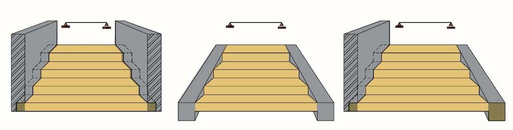
2 Minimum number of risers except for stairs within a dwelling unit, at least 3 risers shall be provided in interior flights. Figure 3.3-1: Continuous supported stairs, Reinforcement details for flight A straight staircases can be defined as one having a single, straight flight of stairs that connects two levels or floors in a building a straight staircase can be simple but quite elegant. Because a straight staircase offers a clear view of the stairs, there is a lower chance of falls or misplaced steps. In contrast, curved staircases often require a lot of attention when you are going up or down one. Straight staircases require more space as compared to curved or platform staircases. Figure 3.3-: Simply supported stairs, design of reinforcement, Reinforcement details

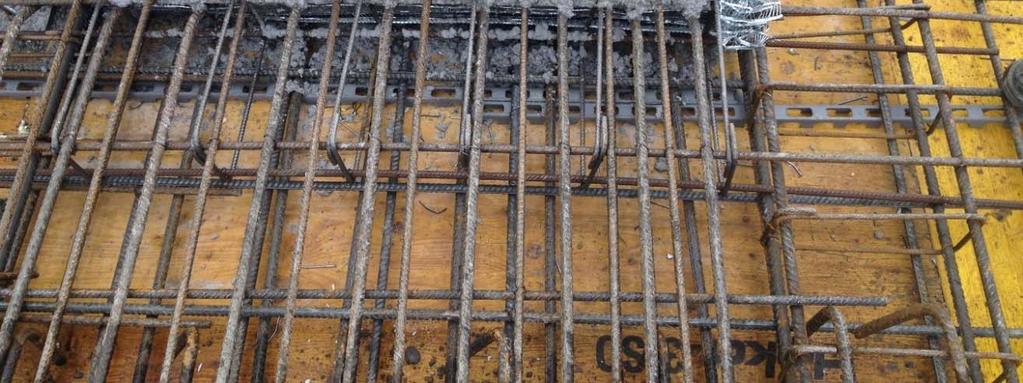
3 The stairs slab is designed for maximum shear and flexure. Main reinforcement runs in the longitudinal direction, while shrinkage reinforcement runs in the transverse direction. Special attention has to be paid to reinforcement detail at opening joints, as shown in figure Figure 3.3-3: Steps cantilevering from a wall or a beam Figure shows a stairs cantilevered from a reinforced concrete beam. The effective length of a cantilever reinforced concrete stairs and beams where this forms the end of a continuous slab is the length of the cantilever from the centre of the support. Where the slab is an isolated cantilever the effective length is the length of the cantilever from the face of the support.

4 Figure 3.3-4: Longitudinally supported stairs, bending moment and shear forces diagram Loading: Dead Load: The dead load, which can be calculated on horizontal plan, includes: 1. Own weight of the steps.. Own weight of the slab. For flight load calculations, this load is to be increased by dividing it by cos to get it on horizontal projection, where a is the angle of slope of the flight. 3. Surface finishes on the flight and on the landings. For flight load calculations, the part of load acting on slope is to be increased by dividing it by cos to get it on horizontal projection. Live Load: Live load is always given on horizontal projection. Longitudinally supported stairs may be supported in any of the following manners: 1. Beams or walls at the outside edges of the landings.. Internal beams at the ends of the flight in addition to beams or walls at the outside edges of the landings. 3. Landings which are supported by beams or walls running in the longitudinal direction figure 3.3-5, figure 3.3-6, figure 3.3-7, figure Figure 3.3-5: Longitudinally supported stairs due to walls, beams


5 Figure Figure 3.3-7

6 Figure 3.3-8: Simply supported steps supported by two walls, beams and a combination of both

7 Figure 3.3-9
 on both sides and carries a live load of 3kN/m.")
8 Figure Example 3.3-1: Design a straight flight staircase in a residential building that is supported on reinforced concrete walls (center-to-center) on both sides and carries a live load of 3kN/m. The risers are 163 mcm and goings are 300 cm. Stair thickness required to satisfy deflection requirements is given by h = 0mm The depth of landing slab is hp = 0 mm = 9 deg Calculation model: Load calculation The section b-c: Calculation of replacement shoulder height: v v cos ( ) h v v 0.143m h 1 h m h h 1 h d h 0.31m Thickness staircase shoulders h = 0.31 m
9 kn 1 q1 s h5 m 3 q1 d q1 s 1.35 q1 s kn m q1 d 1.398kN m cos( ) floor layer shoulders q s.106 kn m q d q s 1.4 q d.948kn m Section a-b, c-d: Thickness staircase landings h p 0.0m q3 s h p 5 kn q3 d q3 s 1.35 q3 s 0.57kN m q3 d 0.77kN m m 3 cos ( ) Layer floor landing: q4 s kn m q4 d q4 s 1.35 q4 d.03kn m Imposed loads Circulation areas v 1s 3 kn v 1d v 1s 1.5 v 1d 4.5kN m m The total surface load on board: q bcs q1 s q s v 1s q bcd q1 d q d v 1d q bcs 14.89kN m q bcd kN m q cds q3 s q4 s v 1s q cdd q3 d q4 d q cds 5.076kN m q cdd 7.30kNm v 1d Sectional forces: L 600 mm L 550 mm L1 100 mm L mm The calculation of bending moments: q cdd L M a q bcd q cdd L L L3 1 M a kN m m q cdd L M d q bcd q cdd L L L1 1 M d kN m m q cdd L L L3 L M ad q bcd q cdd L 0.5 L1 4 L L1 M ad kN m m

10 The calculation of reactions A, B Figure L L3 q cdd L A q bcd q cdd L 0.5 A kn L m L1 L L3 q cdd L B q bcd q cdd L B kn L m L1 Dimensioning: Bending moment over the support: M a kN m m b 1m h 0.m f cd 11.5MPa f yd 375MPa f yk 410MPa See diagram B3-B3.3 M a bd f cd A std bd 100 A std 1.01cm f cd We provide 7 16 Ast = cm
11 x u 0.033m x d x 0.04m x u 0.8x z d z 0.18m 16mm n 7 A s1 A s1.011cm A st na s1 4 A st cm M u A st f yd z M u kN m M u M a b. Cross section between the supports Mad = kn m 16mm a st 0mm d 0.197m d h a st M ad m b bd 1m h 0. f cd z d z 0.178m A stm bd A stm 8.3cm we provide 16mm n 5 f cd A s1 4 A s1.011cm A st na s1 A st cm M u A st f yd z M u kN m M u M ad