Urban Design Manual URBAN DESIGN GUIDELINES PRIVATE REALM DEVELOPMENT
|
|
|
- Rosemary Ward
- 5 years ago
- Views:
Transcription
1 URBAN DESIGN GUIDELINES PRIVATE REALM DEVELOPMENT These Urban Design Guidelines have been prepared in order to assist developers and their agents in preparing development application submissions to the Township of Centre Wellington. These standards assume ideal conditions. There will be sites where due to competing objectives or the inherent limitations of the specific site, it will not be possible to meet the standards. In such cases, the reader/designer should consult with staff to discuss the best method of achieving the optimum design for the respective site. For guidance with respect to the Township s approval processes for new urban development, please refer to the following separate documents Centre Wellington Site Plan Approval manual and Centre Wellington Subdivision Plan Approval Manual. For guidance when constructing public infrastructure which will be transferred to the Township or another public agency, please refer to the separate document: Centre Wellington Development Standards Public Infrastructure The Township of Centre Wellington wishes to acknowledge the City of Kitchener for its permission to use City documents as a basis for the development of these Urban Design Guidelines. 1
2 INFRASTRUCTURE, STREETS AND SITE DESIGN 1.0 ACCESS TO ROADS Definitions Access The means by which vehicles are provided with ingress from a public or private property to the roadway. Commercial access Provided access to a property being used other than for a residential use of six units or less or farm or field uses. A high volume commercial access provides access to facilities which generate higher volumes of automobile traffic and/or heavy truck traffic, i.e. shopping centre. Non-commercial Access A non-commercial access is one providing access to a residential use of six units or less or to agricultural land, including field accesses. Radius The curved outer edge of an access connecting the throat to the curb line. Low Speed Roadway One with a posted speed limit of less than 70 km/h. High Speed Roadway One with a posted speed limit of equal to or greater than 70 km/h. Throat Width Is identified by the minimum width dimension at the intersection of the radius with the parallel portion of the access. Standards SIGHTLINES FROM DRIVEWAYS The location and maintenance of driveways and adjacent landscaping shall preserve the safety of passing pedestrians, cyclists, and motorists. The following chart indicates the number and location of permitted accesses for Township and County roads. 2
3 Number and Location of Access for Township and County Roads Number of Access Allowed Minimum Dimension from Non- Signalized Intersecting Highway Minimum Dimension from Signalized Intersecting Highway Minimum Dimension from Pedestrian Signals Minimum Dimension from Adjacent Non- Commercial Access Minimum Dimension from Adjacent Commercial Access Minimum Dimension from Adjacent High Volume Commercial Access Minimum Dimension from At Grade Railway Crossing Minimum Dimension from Abutment or Structure on a Highway (note 1) (note 4) (note 2) (note 2) (note 3) (note 4) (note 4) (note 5) One 16.0 m 33.0 m 33.0 m 7.0 m 13.0 m 37.0 m 8.0 m Varies One 28.0 m 55.0 m N/A 8.0 m 16.0 m 59.0 m 8.0 m Varies One 33.0 m 65.0 m 65.0 m 13.0 m 20.0 m 69.0 m 13.0 m Varies One 55.0 m m N/A 16.0 m 24.0 m m 13.0 m Varies One 15.0 m m m 37.0 m 69.0 m m m Varies One m m N/A 59.0 m m m m Varies Notes: 1. Need must be demonstrated and approved where multiple accesses are requested 2. Minimum dimension shall be measured from centreline of access to property line abutting an intersecting highway 3. Minimum dimension shall be measured from centreline of access to centre of crosswalk. 4. Minimum dimension shall be measured from centreline of access to centreline of adjacent access 5. Minimum dimension shall be measured from centreline of access to property line abutting railway right-of-way Throat Width 3.7 m 6.0 m 4.6 m 7.6 m 7.6 m 9.0 m 9.0 m Variable Variable Figure 2.1: Number and Location of Access Point 3
4 2.0 SURFACE PARKING FACILITES Definitions Parallel Parking The arrangement of parking spaces in such a manner that the side of each vehicle is parallel to the travelled portion of the aisle or driveway. Angle Parking The arrangement of parking spaces in such a manner that the side of the vehicle when parked is at an angle to the travelled portion of the aisle, lane or driveway. Angle parking includes 90 degree parking layouts. Standards Parking Areas Slope of parking area and aisles 0.5% minimum, 5% maximum. Design Criteria - Parallel Parking: Width metres minimum Length metres minimum, except the first and last space in any row, which may have a minimum length of 5.5 metres provided it is located a minimum of 1.5 metres from any intersecting road, lane or obstruction. One-way Aisle Width metres minimum. Two-way Aisle Width metres minimum, except where such aisle is designated as a fire route in which case the Emergency Services Policy shall govern. Where both parallel and angle parking are served by one aisle, the minimum aisle width for angle parking shall apply. Driveways maximum gradient of 10%. Design Criteria Street Entrances/Exits: Distance from signalized intersections minimum 65 metres. Distance from unsignalized intersection minimum of 33 metres. Design Criteria Traffic Circulation: In areas where traffic circulation may require guidance for directional movement and where painted arrows are not adequate to direct traffic safely or in an organized manner for optimum site circulation, traffic signs, delineators, markings or other traffic control measures or devices will be required. In commercial areas, right-of-ways connecting adjacent properties will be encouraged. Design Criteria Barrier Free Parking: Barrier free parking is to be supplied for all parking facilities as per the standards provided in the Barrier Free Accessibility section, Section 5.0. Figure 2.1: Parallel Parking Dimensions Design Criteria Angle Parking: The width of angle parking spaces shall not be less than 2.6 metres. The length and standard dimensions shall comply with the minimum standards shown in the chart below. All aisles serving angle parking shall be restricted to one way traffic with the exception of 90 degree angle parking layouts. All angle parking spaces shall be plainly marked in accordance with the approved site plan. 4
5 Design Criteria Curbing: Figure 2. 2: Angle Parking Dimensions Angle Parking Dimensions: AN 0 W L A M C m 5.5m 7.3m* 18.3m 2.6m m 5.7m 6.7m 18.1m 2.6m m 5.9m 6.1m 17.8m 2.6m m 6.0m 5.8m 17.7m 2.7m m 6.0m 5.6m 17.7m 2.8m m 6.1m 5.5m 17.6m 2.9m m 6.0m 5.5m 17.6m 3.0m m 6.0m 4.6m 16.6m 3.2m m 5.9m 4.0m 15.8m 3.4m m 5.7m 3.4m 14.8m 3.7m m 5.5m 3.4m 14.4m 4.0m Legend: AN 0 - Angle of Parking W - Width of Stall L - Length of Stall A - Width of Aisle M - Width of Parking Module C - Stall Width Parallel to Aisle * m for Single Parking Row In industrial areas, poured concrete curbing is required to define entrances and where required by the Storm Water Management Scheme. Curbing will also be required to maintain the integrity of the pavement due to drainage or grading concerns and along all passenger vehicle parking and circulation routes. Driveways for truck traffic will have poured concrete curbing to a minimum of 3 metres behind the property line and/or at the start of the turning radii behind the property line, whichever is greater, only when the street is curbed. In all other types of development continuous poured concrete curbing (15 cm high) is required in the following locations: Around traffic islands minimum of 2.6 metres wide (measured from back face of curb to back face of curb). Adjacent to vehicular parking stalls and landscaped areas. Defining vehicular ingress and egress. Sidewalks adjacent to vehicular parking stalls and internal traffic routes. Barrier free drop-off zones and parking spaces are to be flush with the adjacent sidewalk. Design Criteria Surface Treatments: Hot-mixed asphalt, concrete or equivalent is required for all areas on site except: Portions of industrial sites which are behind the front facade and are not used for passenger vehicle parking or circulation. Parking lots for Township parks use. Fire access routes as per the Ontario Building Code. 5
6 Loading Docks and Vehicle Repair in the Township Industrial Park: Loading/unloading areas and transfer areas shall have asphalt or concrete surfacing together with a collection system to collect all oils, vehicle fuels or spilt chemical products for all vehicle servicing/repair and storage associated with vehicles undergoing repair. The design and grading of all loading docks should accommodate the anticipated size of truck and required turning movements. 6
7 3.0 OUTDOOR LIGHTING Definitions Footcandle -The standard used to specify the measured intensity of lighting. Glare - The discomfort or impairment of vision experienced when parts of the visual field are excessively bright in relation to general surroundings. Disability Glare - Glare which impairs the ability to see detail without necessarily causing visual discomfort. Discomfort Glare - Glare which causes visual discomfort without necessarily impairing the ability to see detail. Direct Glare - Glare caused when excessive bright light sources in the visual field are seen directly, e.g.: lamps which are inadequately shielded. Reflected Glare - A term used to describe various visual effects, such as reduction of contrast, discomfort or distraction, produced by reflection of light sources or other bright areas in glossy or semi-matt surfaces. Illuminance - (Unit: Lux) The luminous flux density at a surface i.e., the luminous flux incident per unit area. (This quantity was formerly known as the illumination value or illumination level.) One Lux is equal to one lumen per square metre. One footcandle is equal to one lumen per square foot. One footcandle = Lux. Vertical illuminance is measured at 1.5 metres above ground level. Lumination Level - The minimum level of illumination for the specified area measured on a horizontal plane. Luminance - The physical measure of stimulus which produces the sensation of luminosity (brightness) in terms of the intensity of the light emitted in a given direction (usually towards the observer) by unit area of a self-luminous or transmitting or reflecting surface. It is measured by the luminous intensity of the light emitted or reflected in a given direction from a surface element divided by the area of the element in the same direction. The SI unit is the candela per square metre (cd/sq.m.) Standards Effective outdoor lighting improves visibility, increases safety, provides security and enhances the Township s night-time environment. Improperly installed lighting can be extraordinarily powerful and create problems of excessive glare, light trespass, high energy use and skyward light pollution. This lighting standard recognizes the benefits of outdoor lighting and provides clear guidelines to help maintain and compliment the Township of Centre Wellington s character and contribute to the safety and security of its citizens and visitors. It is intended to reduce the problems associated with improperly designed and installed outdoor lighting. Design Criteria Glare Control: Glare is excessive brightness that causes discomfort or impairment of vision. Outdoor lighting must be aimed, located, designed, fitted and maintained so as not to present a hazard to drivers, pedestrians or adjacent users by impairing their visibility or create a nuisance by projecting or reflecting objectionable light onto neighbouring properties. All outdoor lighting equipment and fixtures shall be properly shielded and directed downward. Lighting sources are not to be visible from adjacent properties or on-site residential units. Glare control must be achieved through the use of cutoff fixtures, shields and the appropriate application of the fixture mounting height, wattage, aiming angle and fixture placement. Design Criteria Light Pollution, Night Sky Controls: Light pollution is considered undesirable and many people feel that it reduces the enjoyment of the night sky. Effective lighting systems must be designed to eliminate direct and indirect skyward lighting. The Township of Centre Wellington requires the use of full cutoff luminaries that direct no light above the horizontal plane. For all area lighting, luminaries should be used and equipped with devices for redirecting light such as shields, visors or hoods. Design Criteria Light Trespass: 7
8 Light trespass is the unnecessary illumination of adjacent property. The Township of Centre Wellington requires that the illumination levels at all property lines not exceed 0.5 footcandles. Lighting complaints are frequently due to nuisance glare or excessive brightness in the normal field of vision even though there may be no measurable light at ground level, there is the complaint that, light is shining in my window. Such concerns can be addressed by containing light within the design area and carefully selecting, locating and mounting well-shielded luminaires. Design Criteria Illuminance: Illuminance determines the amount of light incident on a surface, measured in lux or footcandles. Illuminance levels provide an effective method of measuring the performance of a lighting design. Illuminance uniformity is measured by the ratios Maximum to Minimum and Average to Minimum. These ratios provide a measure of the consistency of lighting across a site and provide assurance that the illuminance is within a range that the human eye can properly discern all objects in its field of view. The following charts indicate the required illuminance levels and uniformity ratios for various types of use. Outdoor Parking Area Lighting Requirements for Industrial, Commercial and Institutional: Measurement Horizontal Illumination (footcandles) Vertical Illumination (footcandles) Minimum Average Maximum Uniformity Horizontal Vertical Maximum:Minimum 15:1 20:1 Average:Minimum 4:1 5:1 Gas Stations: Light levels for gas stations should be adequate to facilitate on-site activities without producing excessive brightness. All light fixtures mounted on canopies must be recessed or flush with the bottom surface of the canopy. Areas away from the pumps used for parking or vehicle storage should be designed in accordance with the Outdoor Parking Area Lighting Requirements. Area Around the Pump and Under the Canopy: Measurement Horizontal Illumination (footcandles) Minimum 5 Average 20 Maximum 25 Uniformity Maximum:Minimum 5:1 Average:Minimum 4:1 Driveway and Laneways: Measurement Illumination (footcandles) Average Horizontal 0.5 min. 0.2 Average Vertical 0.5 min. 0.2 Uniformity Maximum:Minimum 10:1 Car Dealership Lighting: Automobiles are typically placed on display adjacent to the roadway. The lighting of this area should meet the needs of the business without producing excessive brightness. The lighting should not compromise motorists' visibility on the roadway or that of the customer viewing the merchandise. The fixtures should be placed between the roadway and the merchandise area such that cut-off and low-glare luminaries are aimed directly at the front row. Every effort should be made to minimize reflected glare off of the windshields. 8
9 Car Dealership Display Areas: Measurement Display Areas Adjacent to Public Rightof-Way All Other Internal Display Areas Maximum Horizontal Illumination (fc) Uniformity Maximum:Minimum 5:1 10:1 Landscape, Façade and Sign Lighting: Vertical surface illumination and accent lighting can provide a sense of security and mitigate shadows and provide important aesthetic benefits. All building facades, landscaping and sign lighting should be designed to eliminate direct up lighting and prevent glare onto neighbouring properties and roadways. Submission Requirements for Outdoor Lighting Plans: Approval of a site plan may require the submission of an Outdoor Lighting Plan. The contents of an Outdoor Lighting plan which must be submitted for review are outlined in the Centre Wellington Site Plan Manual 9

10 4.0 BARRIER FREE ACCESSIBILITY Definitions Please note: the Ontario Accessibility for persons with Disabilities Act, and regulations made under that Act, shall supercede the provisions of this section in any situation where the Act or regulations are more prescriptive. Barrier Free Access refers to the continuous unobstructed access, connecting all elements and spaces of a building or facility. Exterior accessible routes may include parking access aisles, ramps, crosswalks at vehicular ways and barrier free accessible doorways at all entrances and exits. Standards Designated Parking Requirements: Designated surface parking spaces shall be provided for use by persons with disabilities in parking lots associated with all public facilities and in parking areas serving residential, commercial, industrial and institutional developments. Hospitals and medical centres will be required to have additional designated parking facilities. Located such that persons do not need to travel behind parked vehicles. For shopping malls, large complexes or where multiple buildings exist on a site, the required number of designated spaces should be evenly distributed to ensure available parking at all public entrances. The entrance nearest the designated parking spaces must be equipped with a power door operator. Located as close as possible to a required passenger elevator. Provide a minimum vertical clearance of 2.75 m (see Figure 4.1). Asphalt within designated parking spaces should be benched / ramped flush with the adjacent curb or sidewalk. Right Angle and Parallel Parking Space Size: "Parking space dimensions for barrier-free access are contained in the Centre Wellington barrier-free standards manual" Designated barrier free parking must be designed to achieve the following criteria: Adjacent to the barrier free entrance(s) of each building and connecting with the barrier free path of travel. Provide sufficient clearance around vehicles, light standards and site furnishings. Located away from designated fire routes, intersections or commercial loading zones. Figure 4.1: Vertical clearance at passenger loading zone Provide a level, non-slip, non-glare, textured, hard surface. Designated parking space(s) are to be painted with the international symbol of accessibility. The symbol shall be painted with yellow solvent-based traffic paint on a minimum 1.5 m x 1.5 m blue solvent-based traffic paint background. Landscaping and other design features shall be used to prevent vehicles from protruding over barrier free paths of travel 10
. Ensure that signage does not obstruct pedestrian flow to adjacent areas. Provide directional signage in large parking areas or for hidden parking spaces (see Figure 4.2).")
11 Incorporate required designated parking signage 1.2 m above grade, m from curb edge, or on a building face within 2.0 m of curb. Signs mounted on moveable bases are unacceptable (see Figure 4.4). Ensure that signage does not obstruct pedestrian flow to adjacent areas. Provide directional signage in large parking areas or for hidden parking spaces (see Figure 4.2). Signage may be obtained through the Township Public Works Department (519) Figure 4.3: Sign Location for Multiple Parking Bays Designated Interior Parking Space Requirements: Where indoor parking facilities are provided, designated parking spaces for persons with disabilities must be provided on at least one parking level with barrier free access to the passenger elevator lobby through a door equipped with a power door operator. The designated spaces should be located as close as possible to the barrier-free accessible elevator and have a vertical clearance of 2.75m for use with personal modified vans (see Figure 4.1). Figure 4.2: Sign pointing to designated parking spaces for persons with disabilities Passenger Loading Areas: Pedestrian loading areas or drop-off zones should be provided at all main barrier-free entrances and connect with the barrier-free path of travel. See Figures 4.4 and 4.5. Pedestrian loading areas or drop-off zones must be designed to achieve the following: Design Criteria: Minimum dimensions of 5.2 m width and 7.0 m length. Where the passenger loading area is adjacent to a flush grade sidewalk, the width of the loading space may be decreased to 3.9 m (see Figure 4.5). 11

12 A minimum vertical clearance of 2.75 m (see Figure 4.1). Passenger loading areas must be visible from the main barrier-free entrances and provide benches or seating to the side of pedestrian routes so that persons can see and be seen while waiting to be picked up or dropped off. Located so that persons do not need to travel behind parked cars and/or across a traffic lane. Located away from designated fire routes, intersections or commercial loading zones. At building entrances, overhead protection such as canopies or other structures shall be provided where possible and have a vertical clearance of 2.75 m to allow for specialized transit use. Provide a level, non-slip, non-glare, textured, hard surface having a slope of between 1% and 3%. Identify passenger loading areas with proper signage so that motorists are not confused with parallel parking spaces. Figure 4.4: Sign Indicating Parking Spaces for Persons with Disabilities Provide directional signage in large parking areas or for hidden passenger loading areas (see Figures 4.2). Note: Also see the Ontario Building Code for fire access route design requirements. 12

13 Figure 4.5: Passenger Drop-off and Entrances Minimum Standards Figure 4.6: Building Entrance, Parking and Drop-off Standards 13
14 Sidewalks: Sidewalks also refer to walkways and pathways for this document. Sidewalks, curbs and grading are to be designed in a manner that provides maximum assistance for persons with mobility disabilities without creating hazards for persons who are visually impaired. Ensure that all grading of the barrier-free path of travel is less than 5% and that the landing areas adjacent to curbs do not exceed 2% in any direction. All transitional grade changes on sidewalk areas shall be less than 3% wherever possible (see Figure 4.7). The minimum width for a sidewalk is 1.5 m. This allows enough width for two people in wheelchairs to pass and also for the piling of snow along the edges without obstructing pedestrian traffic flows during the winter months. Sidewalks must be designed to achieve the following: Design Criteria: Slopes greater than 5% must be designed as a ramp with handrails on both side (see Figure 4.9). Provide non-slip, non-glare surfaces for sidewalks. Do not include exposed aggregates or ridges which allow water or ice accumulation; poured in place concrete with a broom finish perpendicular to the path of travel (preferred) or asphalt. Provide textured surface at key locations (sidewalk edges, road intersections) to indicate changes in the path of travel. Flush curbs are required at all intersecting roadways. Asphalt within parking areas must be benched / ramped flush with the adjacent curb or sidewalk Where barrier free parking spaces or loading zones are provided not immediately adjacent to a main entrance, flush curbs must be provided along the barrier free path of travel. Provide barrier-free walkways between all barrierfree entrances, parking, passenger loading areas, municipal sidewalks and outdoor amenities i.e. telephone seating areas, playgrounds, parks. Be a minimum of 1.5m in width and provide sufficient additional space to accommodate expected site furnishings, equipment and signage so as not to restrict the required clear path of travel. Where two sidewalks meet, they shall meet at the same grade (i.e. no steps). Continuous slope shall be between 0% and <5% with a cross-slope between 1% and 2%. Eliminate or minimize cross-slope on walkways where the grade is greater than 3%. Where sidewalks have a slope of between 2% - and 5%, provide level resting areas every 30 m. Rest areas are to be a minimum of 1.8 m wide and 2.2 m long. 14

15 Figure 4.7: Sidewalk Grades and Flush Curbs 15
16 Ramps: In circumstances where there is a grade change of 5% or greater, ramps with handrails are necessary to ensure a barrier-free path of travel. Ramps must be located as close as possible to the most direct barrierfree path of travel and designed in a manner which complements the overall design of the building and site. Ramps must be designed to achieve the following: passage of a sphere more than 13 mm in diameter (see Figure 5.8) and shall have a slip-resistant, continuous and even surface. Provide colour and texture contrast at the top and bottom of ramps. Ramps and landings which are not at grade or adjacent to a wall shall have protected edges, possibly combined with the railing design. Design Criteria: Ramps shall have a maximum internal clear width of 1.1 m. Provide a level area at the top and bottom of a ramp of at least 1.67m x 1.67 m. If a door is provided, the landing shall be extended at least 0.6 m beyond the latch of the door opening. Provide a minimum vertical clearance of 2.1 m. Avoid obstacles intruding into ramps (i.e. sandwich board signs, overhanging shrubs/trees, etc.). Preferred maximum slope of 6%. Provide handrails on both sides of ramps. Figure 4.8: Grate Openings A handrail is always required at an elevation change of 0.6 m. Provide landings where there is an abrupt change in direction and at intervals not more than 9 m along the horizontal length of the ramp (see Figure 4.9). Provide non-slip, non-glare surfaces. Do not include aggregate or ridges which allow water or ice accumulation. Provide poured in place concrete (preferred), asphalt or wood. Poured in place concrete ramps should have a broom finish which is perpendicular to the path of travel. Surfaces of ramps that form a barrier-free path of travel shall have no opening that will permit the 16
17 Figure 4.9: Ramp Design 17
18 Steps: In circumstances where there is a change in grade, steps are often necessary. In such instances the steps should be located as close as possible and perpendicular to the most direct barrier-free path of travel. The stairs should be designed in a manner which complements the overall design of the building and its site. Design Criteria: Provide a minimum clear width of 1.8 m. Treads and risers shall have a uniform rise and run throughout a flight of steps. Rise shall be a minimum of 125 mm and a maximum of 200 mm. Run shall be a minimum of 255 mm and a maximum of 355 mm. Flights of steps should not exceed 1.5 m in height between changes in level without a landing. Provide a minimum vertical clearance of 2.1 m. A cross-slope of 1% is recommended to ensure that steps are well drained and do not allow ice formation. Provide a level non-slip, non-glare textured, hard surface. Do not include exposed aggregate or ridges which allow water or ice accumulation. Provide poured in place concrete (preferred), wood or concrete pavers. Poured in place concrete steps should have a broom finish which is perpendicular to the path of travel. Provide colour and texture contrast at the top and bottom of flights of stairs and on stair nosings. (See Figure 4.10) Use a colour/lightness contrasted strip, a maximum of 50 mm deep on the leading edge on the tread and vertical face of the nosing. Steps must be illuminated to a minimum level of 10 foot candles. Figure 4.10: Stair Design Nosing should not project. If a shadow line is proposed for decorative purposes, it should not have a height exceeding 12 mm or a radius exceeding 13 mm (See Figure 4.11). Handrails: Handrails are common site elements and should be provided on both sides of ramps and stairways and must be designed to achieve the following: Design Criteria: Handrails should be provided at a height between 865 mm and 965 mm as measured vertically from a line drawn through the surface of the ramp. At facilities used by children, a lower set of handrails with a recommended height of mm should be provided. Where handrails are used extensively by both young users and adults, a double set of handrails is suggested. Handrails should be a minimum 30 mm in diameter and a maximum of 40 mm. Provide a clearance between every handrail and any wall to which it is fastened. Minimum clearance is 40 mm, preferred 60 mm (see Figure 4.12). 18

.")

19 Figure 4.12: Handrail Design Extend horizontally not less than 300 mm beyond the top and bottom of the ramp or stairway and curve to the wall or post (see Figure 4.13). A minimum clearance of 1 m is required between handrails. Handrails must terminate in a manner which will not obstruct pedestrian travel or create a hazard (see Figure 4.13). Figure 4.13: Handrail Extensions Figure 4.11: Stair Tread and Nosing Design 19
20 Entrances and Automated Door Activators: All main barrier-free entrances must be located prominently and designed to achieve the following: Design Criteria: A textured floor surface should be provided on both sides of doorways to alert those with visual impairment. Barrier-free entrances should be sheltered from the elements and located adjacent to designated parking and passenger loading areas. Grade level fire doors and exits must be accessible and connect directly with accessible exterior, as well as interior circulation routes. Door openings should have a minimum clearance width of 915 mm, with the door in the open position (door handles, push bars, etc. must not intrude into the clearance). Thresholds are strongly discouraged. If required, a threshold should be colour/brightness contrasted and be a maximum of 13 mm in height. Automatic door activators must be provided to allow persons with a disability, parents with children, shoppers with full hands and people with strength limitations easy access and exit. Automatic doors may be activated with either a motion sensor, pressure plate or push button. Motion sensors are the preferred automatic door activators. They should allow a minimum of 15 seconds before closing from a fully open position (see Figure 4.14). Pressure plates should extend beyond the full swing of swinging doors in a manner which does not require persons using wheelchairs or scooters to back up. Large expanses of clear glass near entrances must be marked with a colour/brightness contrasted, continuous strip 100 mm wide, 1350 mm from the finished floor. Figure 4.14: Motion Sensor Detector Zones Transitional illumination between exterior and interior lighting conditions must be provided for both day and night use. Doors and door frames should be colour/brightness contrasted from surroundings. Door edges and jambs should not be excessively sharp. Where possible, entranceways should be covered to keep snow, ice and rain off the front entranceway platform. Push buttons to activate doors should be placed 750 mm above grade on a wall, post or handrail in a manner, which does not create pedestrian/door conflicts. Push buttons should be able to be located by vision or touch and be a minimum of 900 mm in front of the door(s). Push buttons should be large square or round plates, at least 100 mm in diameter, with maximum colour contrast for good visibility. All automatic doors should be integrated into an emergency backup system. Automatic doors should be of lightweight construction and easy to open in the event of a power failure. Automatic swing doors require guardrails on both sides if opening towards the operator. Guardrails should have a second rail not more than 680 mm above grade and a rail or kick plate not more than 20

21 75 mm above grade (see Figure 4.15) Guardrails are to be colour contrasted to surrounding area. deep beside each bench for wheelchair or scooter users (see Figure 4.16). Refuse and recycling receptacles should be provided at appropriate waiting/rest areas. Gates and doorways are to be a minimum of 920 mm in width and should not occur at corners, turns or congested areas. Figure 4.15: Required Guards at Out-swing Automatic swing doors must have sensing devices to stop and/or slow door movements when an obstruction is encountered in the path of the swing door. Signage (i.e. international symbol of accessibility for persons with disabilities) must identify all public use accessible doors. It should be placed in a prominent location indoors and outdoors, preferably on both sides of the door(s), at a height of 1.2 m to 1.5 m and be a minimum of 125 mm in diameter. Amenities: Amenities such as waiting and rest areas, playgrounds, picnic areas, paths and trails are to be constructed so that all users can equally utilize facilities and be designed to achieve the following: Design Criteria: Waiting and rest areas should be provided at regular intervals of 90 metres along barrier free paths of travel, as well as at drop off areas, bus stops and telephone booths. Benches should be a minimum length of 1200 mm and provide a space 1000 mm wide and 1200 mm Figure 4.16: Waiting and Rest Area Playground equipment should be designed to provide barrier-free opportunities that encourage use by all children. Similarly, surfacing materials should provide adequate cushioning abilities and allow barrier-free travel. All playground equipment must be approved by the latest edition of the Canadian Standards Association (CSA). Play areas for children in public spaces must be accessible to all children and their parents or care givers. Whereas it may not be possible to have complete accessibility to every item and piece of play equipment in the play area, the play needs of all children must be considered and design of play areas must ensure access for both adults and children in the play area. When designing inclusive play areas, careful consideration is to be given to barrier-free access 21
22 from the street into the play area and the availability of rest stations and seating opportunities. In water play areas, avoid tripping edges and raised curbs to allow access by people using mobility devices and use by children and adults with visual impairments. Utilize colour/brightness contrast. In water play areas, water-flow control devices must be designed to be controlled, manipulated and easily reached by preschool children and children with disabilities. Pathways should be free of joints that may cause tripping or the washboard effect on mobility devices such as manual and electric wheelchairs or scooters. Joints should be flush, light and as short as possible. Acceptable pathway surfaces that do not soften with heat or moisture include: HL3 asphalt Concrete Slopes are to be between 0% to 4% wherever possible with a cross-slope between 1% and 2%. Slopes greater than 5% should be designed as a ramp. Where paths and trails are sloped 3% to 5%, provide level resting areas every 30 metres. Resting areas are to be designed according to Figure Provide a continuous, hard, stable, non-slip, nonglare surface. It is recognized that in natural areas, softer surface materials such as limestone screenings are acceptable. Other acceptable materials include asphalt, concrete and wood decking (boards to be perpendicular to the direction of travel with spacing not exceeding 13 mm). Provide colour and texture contrast or a hand rail to define path/trail edges and intersections, changes in direction, building entrances, road intersections and curb ramps. Appropriate signage must be provided. Well-compacted stone dust Consideration should be given to adult care givers who may also be persons with disabilities. A minimum of 2 or at least 10% of picnic areas within a site must be accessible. An accessible approach to the picnic area must be provided from an accessible parking space. A hard surfaced path connecting the parking space to the picnic areas and to other facilities (i.e. washrooms, water etc.) should be provided. Picnic sites should be within 30 metres of accessible washroom facilities. Accessible picnic tables should be on hard, level, well-drained surfaces. The bottom edge of the table top must be no lower than 680 mm above ground level. Trails should be a minimum of 3000 mm wide. 22
23 5.0 PEDESTRIAN AND TRANSIT SUPPORTIVE DEVELOPMENT It is important for all forms of urban development and redevelopment to be made more accessible by public transit. The design of our urban areas has a significant impact on people s ability/willingness to use public transit. While the development of high intensity, mixed use development at nodes and along corridors makes transit use more attractive, there needs to be transit and pedestrian orientations on the streets which feed those transit services. Both the Township of Centre Wellington and the County of Wellington have sidewalk policies which may require either the installation of or the contribution of funds towards the construction of public sidewalks across the frontage of property subject to a development proposal. Please see current Township and County policies for criteria and Engineering staff for current rates. At the time when these Urban Development Guidelines are being developed, the Township of Centre Wellington does not operate a public transit system. It is nonetheless anticipated that continued urban growth will increase the viability of public transit and that it is now prudent to ensure that development henceforward is supportive of potential future transit service. Design Standards Arterial and Collector Roads are to be designed in accordance with the Centre Wellington infrastructure Development Standards document Nodes and Corridors are to be designed in the following manner: Develop compact pedestrian oriented nodes that allow for the ease of use and access to transit by: Designing building entrances to be oriented towards transit stops. Designing arterial and collector roads to travel directly into the interior of the nodes, allowing transfers between transit routes where appropriate. Development should be oriented toward the street and include: Location of buildings as close to the street as possible. Location of parking lots in the rear or side yards of development sites. Minimizing the number of mid-block vehicular access points that cross sidewalks. Minimizing long stretches of walls, berms or solid fences along public roadways. Develop barrier free, pedestrian-supportive amenities along streets as follows: Locate retail stores, service shops and restaurants at ground floor level. Provide amenities to improve the microclimate along streets with features such as: canopies, arcades and landscaping. Provide sidewalks sufficiently wide to accommodate bus shelters and waiting areas, street tree planters, through pedestrian traffic, and an area adjacent to buildings to allow for window shopping. Sidewalk ramps and curb ramps are to be constructed as outlined in Section 4.0. Shopping Centres with transit facilities are to be designed to: Facilitate barrier free pedestrian access and future intensification. Have at least one building face or the main entrance adjacent to an arterial road. Have barrier free pedestrian access from the public sidewalk to the main building entrance. Have on-site lighting to maximize pedestrian safety. 23
24 Provide pedestrian connections between buildings and facilitate pedestrian circulation within parking lots. Maintain adequate distance to adjacent streets and driveways. Subdivisions are to be designed to: Facilitate barrier free pedestrian access to transit stops. Provide sidewalks along both sides of transit routes and according to the Township Sidewalk Policy. Provide curb cuts at all intersections and walkways including mid-block crosswalks and trail crossings (where safe and appropriate). Have barrier free pedestrian links to transit stops provided in either concrete or asphalt. Have the local road pattern provide direct pedestrian access to transit stops and transfer points. Provide for pedestrian safety and natural surveillance of pedestrian links to transit stops ensuring adequate lighting and year round maintenance. Have 95% of the residences, jobs and other activities / uses within 450 m walking distance of a transit stop. Have all multiple dwelling units (housing at a triplex level and up) be within 300 metres walking distance of a transit stop. Integrate neighbourhood features and public spaces with bus stop locations. Transit Stop Waiting Areas and Shelters are to be designed to: Provide direct, convenient and barrier free connection from the sidewalk to the shelter/waiting area and to the bus loading and unloading doors. Provide sufficient lighting to allow for pedestrian safety, surveillance and adequate site lines. 24
25 Figure 5.1: Typical Nearside Transit Stop Figure 5.2: Typical Farside Transit Stop 25


26 6.0 SCREENING OF MECHANICAL AND ROOFTOP EQUIPMENT This section outlines the requirements for the screening of ground-based and rooftop equipment. The primary goals of the guidelines are to provide for the full screening of equipment from public view and to ensure that screening methods contribute to the building design and streetscape. road from the property. Additionally, sight lines from the front or rear face of any surrounding residential properties should be provided. Views approaching the property along all public roads should be illustrated and take into account grade changes. For properties in low lying areas, screening options integrated into the roof design may be necessary. Definitions Mechanical equipment Includes heating, ventilation, and air-conditioning units; compressors; pumps; and other similar powered mechanical equipment. Non-mechanical equipment Includes flues; vents; hoods; satellite dishes; communications equipment; elevator and stair penthouses; access ladders; and other similar non-powered equipment. Roof well An open pit sunk below a building s roof surface. Parapet The portion of an exterior building wall extended above the roofline. Screening wall An independent screen, separate from a building wall. Standards Figure 6.1: Locating this building s rooftop equipment away from the street and incorporating a continuous parapet helps block the equipment from public view. Design Criteria: Buildings abutting residential properties or located on corner lots, at the termination of view axes, or at other prominent locations will be subject to higher rooftop equipment screening standards. Buildings shall have all rooftop mechanical equipment screened from the view of pedestrian and vehicular traffic. Site Plan Requirements: The locations and dimensions of all rooftop equipment must be shown on building elevation drawings. Proposed methods of screening should be provided. If independent or integrated screens are proposed, material and construction details should be provided. Sight line diagrams are required with building elevations. Diagrams should show multiple views to proposed rooftop mechanical equipment from a 1.7 m height at the curb of the opposite side of the Figure 6.2: Rooftop equipment on this building is clustered near the centre of the roof, away from the street and other public spaces 26


27 Rooftop equipment should be clustered and located near the centre of the roof to minimize visual exposure. Solar panels should be screened where possible and incorporated into the slope of the roof line on commercial buildings with the building design. The screening also articulates the roof elevation. Design Criteria for Various Building Types: For low-rise buildings (3 storeys or less), rooftop mechanical equipment shall be fully screened. The preferred rooftop equipment screening methods are roof wells, continuous parapets, or articulated rooflines. If these methods are not possible or appropriate, other methods, such as partial parapets, screening walls, or dedicated rooftop equipment rooms, may be used. Figure 6.5: The peaked roof of this low-rise building screens all rooftop equipment and helps define the intersection where the building is situated. Figure 6.3: Rooftop equipment screening methods used on this building include parapets, an articulated roofline, and centralized location of equipment. Rooftop equipment and equipment screening should be integrated with the building form and shall complement the building s design, materials, colours, and architectural style. The back sides of parapets, screening walls, and raised rooflines should be coloured the same as the front side when visible from public view. For all mid-rise (4-8 storeys) and high-rise (above 8 storeys) buildings, rooftop mechanical equipment shall be fully screened from the public view at street level. Rooftop equipment screening for mid-rise and high-rise buildings shall contribute to an attractive skyline and the view from surrounding mid- and high-rise buildings must be considered. Large mechanical equipment, including refrigeration units for commercial, institutional and recreational buildings should be incorporated into the building design or, alternatively, screened with the appropriate materials. Significant heritage buildings shall have all rooftop equipment fully screened and/or integrated into the building in a way that respects and complements the building s heritage and architectural features. Figure 6.4: Rooftop mechanical equipment for this building is hidden by a screening wall that is integrated Civic buildings shall have all rooftop mechanical equipment fully integrated into building design. 27


28 Commercial buildings including gas stations shall have all rooftop mechanical equipment fully screened. Parapets, detailed cornices, and/or articulated rooflines that enhance the building design should be incorporated, particularly for gas stations located at major intersections. Design Criteria for Screening Ground-based Mechanical and Non-mechanical Equipment: The location of all ground-based mechanical and non-mechanical equipment must be illustrated on the landscape plan and, if fencing is required, also on the site plan. Many types of ground based equipment will require appropriate screening not only to address views into the site from the public realm but also to provide a buffer between uses within the site e.g. screening communal ground-based air conditioner units from private amenity spaces. Figure 6.6: The rooftop equipment on this corner gas station is not screened and is visible from public view. Figure 6.7: Although the rooftop equipment on this gas station is fully screened with materials matching the building, the enclosure is not well-integrated with the building form. Figure 6.8: The articulated roofline on this gas station and car wash fully screens rooftop mechanical equipment and helps create an attractive building design. 28
29 7.0 EMERGENCY SERVICE POLICY FIRE FLOW ANALYSIS REPORT, FIRE ROUTE PLAN, MULTIPLE UNIT IDENTIFICATION Definitions Approved means approved by the Chief Building Official in consultation with the Chief Fire Official. Building shall have the same meaning as that provided in the Building Code Act. Emergency Access (As covered in Section 3) These drivable access right of ways are intended for use by emergency vehicles in to cul de sacs and other cut off areas. They are typically gated or barred by bollards. Emergency Access Routes means a right of way provided to a building for the use of emergency service personnel and vehicles, and provided to protect the building and it s occupants. Fire Route shall have the same meaning as an Emergency Access Route. Street Fronting Townhouse means a townhouse unit where the principal entrance to the unit is located on a city street. 1. Water Supply Except as otherwise stated, these requirements apply to all developments. Fire Hydrants Unless otherwise approved, any development served by private access roads, in which the individual buildings are to be constructed in accordance with Part 9 of the OBC, shall be provided with fire hydrants in conformance with the following: hydrant shall be located within 90m of the principle entrance to each area. The distance from the hydrant to the principle entrance(s) shall be measured using the path that the fire hose would have to be actually laid along, not in a straight line. (Refer to Appendices 1 & 2) b) If additional private fire hydrants are required to meet the requirements of this Subsection the developer shall provide them at their own expense. c) Private fire hydrants shall be constructed and installed in conformance with the Centre Wellington Standard Specifications for Watermains d) Private fire hydrants shall be located with the 100mm Stortz connection facing the private access road. e) Private fire hydrants shall be located within 5m of the private access road, no closer than 3m to any building, and kept visible and accessible at all times. Fire flow from the fire hydrants shall be determined to be sufficient for fire fighting activities in accordance with Centre wellington Fire Flow Analysis Submission Requirements, included in the Site Plan manual. Private fire hydrants shall be tested and maintained annually in conformance with the Fire Code, and at the property owner s expense. a) A fire hydrant shall be located within 90m of the principal entrance to each building. Where portions of the building are completely cut off from the remainder of the building, a fire 29
30 2. Emergency Access Routes These requirements apply to all developments, except where prescriptive infrastructure requirements exist in the OBC. All developments containing emergency access routes required by the Building Code, the Fire Code, or this policy shall be provided with fire route signs in conformance with these Guidelines. Such determination shall be made by the Township's Chief Fire Official in consultation with the Chief Building Official prior to Site Plan Approval in principle for the proposed development. Location of Emergency Access Routes Unless otherwise approved, multiple unit buildings containing townhomes and individual dwelling units, where the principal entrance to the unit or townhome has direct access to the exterior, shall be provided with emergency access routes located so that the principal entrance and every required access opening are located not less than 3 m and not more than 30 m (Appendix 2 Option 1) from the closest portion of the emergency access route, measured along the path of travel, horizontally from the face of the building. Where a developer can show that the 60 m (Appendix 2 Option 2) of provided hose can reach from the fire truck to the most remote room in the dwelling unit, a longer travel distance will be considered. This limiting factor is based on fire apparatus hose loads intended for use in an initial fire attack in a residential setting. This restriction takes into account the ability for the Fire Department to effectively intervene in the dwelling unit, using the standard equipment provided on the vehicles. (Appendix 2) Except as otherwise required, emergency access routes shall be provided to a building so that (Appendix 3): a) for a building provided with a fire department pumper connection (siamese), a fire department pumper vehicle can be located adjacent to the hydrants so that the unobstructed distance from a fire department pumper connection to a hydrant is not more than 45 m. b) for a building not provided with a fire department connection, a fire department pumper vehicle can be located so that the length of the emergency access route from a hydrant to the vehicle plus the unobstructed path of travel for the fire fighter from the vehicle to the building is not more than 90 m, and c) the unobstructed path of travel for the fire fighter from the vehicle to the building is not more than 45 m. d) Emergency access routes shall be located so that the principal entrance and every required access opening are located not less than 3 m and not more than 15 m from the closest portion of the emergency access route. The unobstructed path of travel for the fire fighter from the vehicle to the building shall be measured from the vehicle to the fire department connection provided for the building, except that where no fire department connection is provided, the path of travel shall be measured to the principal entrance of the building. In all buildings, other than those addressed in 2.2, if a portion of a building is completely cut off from the remainder of the building so that there is no access to the remainder of the building, the emergency access routes required by Subsection 2.3 shall be located so that the unobstructed path of travel from the vehicle to one entrance of each portion of the building is not more than 45 m. (Appendix 4) 30
31 Emergency Access Route Design Unless otherwise approved, a portion of a roadway or yard provided as a fire route for fire department use shall (Appendix 4): a) have a clear width not less than 6 m, b) have a centerline radius not less than 12 m, c) have an overhead clearance not less than 5 m, d) have a change of gradient not more than 1 in 12.5 (8%) over a minimum distance of 15 m, e) be designed to support the expected loads of fire department vehicles and be surfaced with concrete, asphalt or other material designed to permit accessibility under all climatic conditions, f) have turnaround facilities for any dead-end portion of the access route more than 90m long, g) be connected with a public thoroughfare, and h) will be considered accessible when the following has been provided; the roadway base coat layer, appropriate signage, and hydrants. c) Fences, landscape walls and building faces located not more than 4m from the limit of the fire route. 2.9 Mounting Height: Between 2 and 2.5m measured from the top limit of the sign to the grade of the fire route surface adjacent to the fire route sign Design and Installation Standards for Emergency Access Route Signs Sign Plate: Materials shall be approved, corrosion resistant metal; lettering, colour, size shall be in conformance with the following figure: Red Circle 19.05cm Black P 10.16cm White Background Sign: 30 x 45cm Black Fire Route 4.45cm Enforced Wording 1.91cm Sign Mounting: mounting methods must be approved. Some methods that will be considered are: a) Standard sign post, b) Light standard or other equivalent utility pole located not more than 4m from the limit of the fire route, or 31
32 Spacing between Signs: not more than 30m spaced such that at least one sign is clearly visible and lettering is legible from all locations within the fire route. Location of Signs: a) Where practical, signs should be located alternating side to side of the fire route. b) Where parking is located adjacent to the fire route and is not delineated from the fire route by curbs, signs may be located on the side of the fire route opposite the parking only. Setback from the Fire Route: Fire route signs shall be at least 0.3m and no more than 4m from the edge of the fire route. A detailed fire route and signage plan shall be submitted for approval prior to final site plan approval in a legible electronic format, preferably PDF or CAD. Plan detail must include width and centerline turning radii of the fire access route, all fire hydrants or other water supplies, fire department pumper connections relative to the buildings, and the location of all fire route signage. This information may be included on the site plan submission. The Fire Route signs shall be installed before any occupancy is granted by the Building Department. The Township's Chief Building Official in consultation with the Chief Fire Official shall inspect the route for compliance when requested to do so by the developer and may order modifications if it does not comply with all requirements. parked vehicles, obstacles and obstructions and must be maintained in a passable state at all times in accordance with the following: a) Snow accumulation shall be removed from all emergency accesses, emergency access routes and fire routes on public property, b) Emergency accesses designated as Emergency Access Routes on site plans shall remain clear from all obstruction and shall be maintained in a passable state at all times by the owner, as required by the Fire Code. c) Emergency access routes and fire routes to all buildings are required to be designed so that there is an unobstructed path of travel for a fire department pumper to the fire department connection of the building, or where there is no fire department connection, for a fire department pumper to the principal entrance of the building, or in instances where 2.2 applies a clear path of travel from the roadway or emergency access route to the principal entrance to each dwelling unit. d) The unobstructed path of travel between the roadway or emergency access route and those terminus locations identified in (c) shall be at least 1.2m in width. If the path is located between parking stalls, then it must be clearly defined to strongly discourage parking with physical barriers and/or signage. The property owner is responsible to ensure that the visibility and legibility of the signs are maintained at all times. Maintenance All emergency accesses, emergency access routes and fire routes located on private and public property shall remain clear from all 32
33 3. Emergency Access Emergency accesses are intended to be provided into areas that would be otherwise cut off, such as cul-de-sacs. These emergency accesses are not intended for normal driving, and are typically only accessible to emergency services by the opening gates or bollards.. Cul-de-sacs The maximum permanent cul-de-sac length is as follows: Residential: m where no secondary pedestrian/vehicular emergency access is provided and number of residential units is less than m where secondary pedestrian/vehicular emergency access is provided. - Secondary pedestrian/vehicular emergency access is required where number of residential units is 50 or greater. Non- Residential: m where no secondary pedestrian/vehicular emergency access is provided m where secondary pedestrian/vehicular emergency access is provided. Note: if secondary access is not provided the permitted uses will be restricted to Low Hazard Occupancy. - Secondary pedestrian/vehicular emergency access may be required depending on the specifics of development proposed (i.e. risk, size, number of employees/public involved) at the discretion of the Township. Consultation with the Township advised at development concept stage to confirm requirements. Notes: - Length is measured from the centre of the culde-sac to the street-line of the intersecting street. - Secondary pedestrian/vehicular emergency access to be located at the end on the cul-de-sac. 33
34 There shall only be one emergency access per cul-de-sac. - Emergency accesses on temporary basis are subject to the same requirements as permanent accesses. - Emergency access routes serving multiple unit residential subdivisions located on a culde-sac shall be included into the overall measurement of the cul-de-sac. - The path of travel measurement shall not be included in the overall measurement of the culde-sac. Non-Residential Subdivisions Cul-de-sacs in non-residential subdivisions shall be discouraged and shall only be permitted in the case where all alternate design possibilities have been determined to be unacceptable. If required, the standards under Residential Subdivisions shall apply subject to the specific requirements listed below: a) The maximum length of a cul-de-sac shall be 150m. b) Cul-de-sacs without an emergency access shall not exceed 60m in length. c) Cul-de-sacs exceeding 60m in length shall require an emergency access leading to a public right-of-way within 60m of the farthest point of the property line of the bulb. Multiple Residential Site Design Multiple residential developments which include more than three residential units, requires emergency access conforming to the following (Appendix 7): a) Any multiple residential development located on any public right-of-way, other than a cul-desac, where the length of the fire access route located in the development exceeds 150m shall be provided with an emergency access or a second means of access to any public roadway located in such a manner that the furthest distance of any part of the access route is not greater than 150m to the emergency access or the public right of way. b) The length of the fire access route located in multiple residential development, other than those located on a cul-de-sac, shall be measured along the centerline of the access route from the where it meets the property line of the public right-of-way. c) The length of the fire access route in multiple residential developments located on a cul-desac shall be measured along the centerline of the access route and the centerline of the culde-sac on which it is located to the property line of the nearest public right-of-way that is not a cul-de-sac. d) The path of travel measurement shall not be included in the overall measurement described in this section. Design and Construction All emergency access routes shall be designed and constructed to the following criteria (Appendix 5): a) The maximum gradient change is to be 1:12.5 (8%) over 15m minimum. b) The design and construction of the emergency access shall conform to diagrams found in Appendix 7. c) The minimum centre line radius is 12m. d) Emergency access shall not exceed 150m in length. e) Both ends of the emergency access shall be protected by either gates or an approved type of removable bollards that can be easily 34
35 removed and replaced year round, conforming to diagrams found in Appendix 7. f) Emergency access signs shall be located at both ends of the emergency access at the owner s expense and to the satisfaction of the Chief Fire Official. g) The construction of an emergency access must be completed prior to occupancy of any unit in a multiple residential or non-residential development in relation to a site plan. h) The construction of an emergency access must be completed prior to the issuance of any building permit in a subdivision or otherwise provided for through the subdivision agreement. i) Where an emergency access intersects with a roadway bounded by a curb, the curb shall be cut the full width of the emergency access, plus required turning radii, so that no more than 5cm difference in height exists at the intersection points. j) A minimum level of completion will include at least a base coat layer, signage and hydrants. Maintenance All emergency accesses located on private and public property shall remain clear from all parked vehicles, obstacles and obstructions and must be maintained in a passable state at all times in accordance with the following: a) Snow accumulation shall be removed from all emergency accesses on public property based on Class 3 classification under the quality standards for winter maintenance activities by the Community Services Operations Department. b) Emergency accesses designated as Emergency Access Routes on site plans shall remain clear from all obstruction and shall be maintained in a passable state at all times by the owner, as required by the Fire Code. c) Access routes to all buildings are required to be designed so that there is an unobstructed path of travel from a fire department pumper to the fire department connection for the building, or where there is no fire department connection, from a fire department pumper to the principal entrance of the building. d) The unobstructed path of travel shall be 1.2m in width. If the path is located between parking stalls, then it must be clearly defined to strongly discourage parking with physical barriers and/or signage. Exemptions The owner/developer may apply to council for an exemption to specific parts of the Emergency Access requirements contained in this policy. a) The Fire Department will support an exemption to the distance requirements contained in Subsections 3.1 or 3.3, assuming no extenuating circumstances affecting emergency service response exist and subject to the following conditions: i) Residential sprinklers conforming to the latest version of NFPA 13D, or other standard acceptable to the Chief Fire Official, and a direct-to-fire monitoring system are installed in all dwelling units located beyond 150m distance requirements contained in Subsections 3.1 and 3.3 ii) The length of the fire access route or cul-de sac in the development for which the exemption is being applied for still cannot exceed 300m in length measured from the property line of the intersecting street, including the length of the cul-de-sac if located on a cul-de-sac. 35
36 b) Other exemptions will be considered for support if alternative solutions are provided that, in the opinion of the Chief Fire Official in consultation with the Chief Building Official, will provide equivalent or increased life safety and hazard protection to affected occupants and buildings. c) Where an exemption has been granted and an alternative measure has been accepted that may require the future property owner to maintain a system or feature, the Township may require the developer or constructor to take adequate measures to ensure that these requirements are disclosed, such as registering this information on title or some other reliable method acceptable to the Township.. 4. Multiple Unit Building Identification / Municipal Addressing a) All buildings must be provided with a municipal address. b) All buildings must be provided with a street number or Multiple Unit Identification sign easily visible from the street or public thoroughfare. c) Addresses shall be provided in a manner that allows easy identification of the building or site, such that principal entrances to buildings or entrance routes are accessed from the street to which they are addressed from d) All multiple unit residential properties, such as apartment buildings, shall ensure an addressing scheme for the building is submitted for approval, consistent with the Council Addressing Policy. Unit Identification sign shall be provided consistent with the guidance below. f) Street fronting townhouses shall be municipally addressed consistent with Council policy. g) Municipal addresses should be proposed early in the development process, to allow the reviewed addresses to be used on documents, such as building permits. h) Where a concern is identified that does not meet the application here, the requirement for an addressing plan shall be identified early in the development process. i) All addressing proposals must be approved. Lots containing more than one building intended for occupancy, may be required to: a) prominently display a multiple unit identification (MUI) sign at each entrance to a public thoroughfare showing the layout of the site, the municipal address, the building identifiers and occupancy unit identifiers. or b) provide a site plan which incorporates private streets, where buildings are individually addressed, and multiple unit buildings are provided with prominent unit identifiers, tied to the private street addresses, or c) any combination of the above, that provides for ease of identification of units and buildings by emergency service personnel during an emergency response,. d) The use of private named streets shall be encouraged, as buildings addressed off of a named street may be incorporated into the 911 system. e) Where multiple buildings are addressed under the same municipal address, a Multiple 36
37 4.3 If required as above: a) the owner shall prepare and submit a colour concept plan of the MUI sign in accordance with the design, construction and location requirements set out below, and obtain approval of the MUI sign prior to the issuance of any building permits/ or site plan approval. Colors or materials that cannot be accurately represented on the concept plan may require submission of materials samples for approval, or b) the owner shall prepare and submit a detailed site plan describing the proposed street structure and addressing scheme, ensuring that all buildings and potential units within a multiple unit building are provided with a readily identifiable addressing scheme. The plan shall be submitted for review and approval, prior to the issuance of any building permits/ or site plan approval, c) where a combination of multiple unit identification and municipal addressing are proposed for the same site, the inclusion of municipally addressed buildings may be included on the MUI sign where the inclusion provides clarification when trying to locate units using the MUI sign, and d) submissions shall be made in a legible electronic format, preferably PDF or CAD. 4.4 All MUI signs shall be designed and constructed by the owner, as follows (Appendix 9): a) all signs shall use reflective letters and markings or be illuminated internally or externally, whichever is appropriate for their design b) all signs shall have contrasting lettering and backgrounds c) the sign shall identify the municipal address of the site in 50mm block letters d) each building identifier and occupancy unit identifier must be identified separately and clearly with numbers and/or letters at least 30mm in size e) each sign shall have a 1.2m clearance from grade and shall not exceed 3.0m in height from grade, or 6.0m² in total area, unless otherwise approved by the Township. f) all abutting public streets, internal roads, fire routes and emergency access roads shall be identified g) the location of the Fire Department water connections and on-site hydrants shall be displayed in red h) an identification YOU ARE HERE label shall be clearly displayed in white letters on a red background i) all signs shall be constructed of durable material by the sign industry and maintained in a legible condition in perpetuity j) signs can be prepared by an independent sign maker or by the City of Kitchener, at the expense of the owner. 4.5 The location of all MUI signs shall be shown on the Landscape Plan drawings. Planting in the vicinity of the sign shall be of a low growing variety (a maximum mature height of 1.0m) and maintained so as not to obstruct the sign. 4.6 All MUI signs must be installed prior to the occupancy of any units within the development, in accordance with the following location requirements: a) a MUI sign is required to be installed on the right side of each entrance driveway to the site within 10m of the property line 37
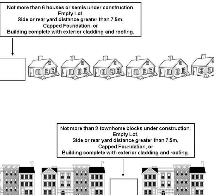
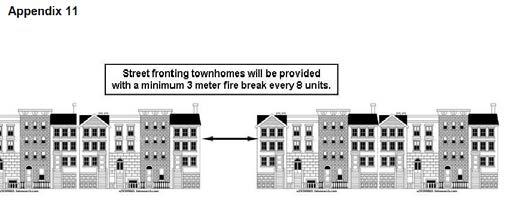
38 b) a MUI sign may not be located within the driveway visibility corner formed by the projection of the intersection of the front lot lines and driveway edge, connecting them 4.57m from their point of intersection c) a MUI sign must be located on the owner s property not more than 1.2m from the edge of pavement of the internal driveway, situated at a 45-degree angle to the driveway. When a sidewalk is located between the MUI sign and the driveway, the sign must not be located less than.6m from the sidewalk and not exceeding 1.8m from the edge of the pavement of the internal driveway. 4.8 Once an MUI sign is installed, the Chief Fire Official shall inspect the sign for compliance and may order the sign to be modified if it does not comply with all requirements. 4.9 All MUI signs must accurately reflect any changes to the site as a result of redevelopment or building additions and must be changed at the time of undertaking the building or site alterations All buildings containing multiple units, where the units are accessed from interior public corridors, shall submit an addressing design concept for review and approval In all cases developers and designers shall ensure they are familiar with and following the City of Kitchener Council policy on addressing. 5. MISCELLANEOUS 5.1 Fire Breaks During Construction (Appendix 10) a) Each builder is required to submit a plan or policy of designating fire break lots in accordance with 5.1. b) The fire break lot designation will be noted on the building permit application, in the tracking system and on the building permit. c) The construction of the building upon the foundation of the fire break lot cannot commence until the roofing and exterior cladding has been completed on the buildings located to the sides and rear (if less than a 7.5m rear yard). d) It is the responsibility of the Building Inspector to monitor compliance with the fire break lot policy. e) The Building Inspector has the discretion to alter the designated fire break lot on site; provided the principle of a maximum of six framed singles or semi-detached dwelling units or two townhouse blocks is not compromised. f) Fire break lots shall be provided so that: i. for single family homes and semidetached homes not more than six buildings are grouped adjacent to each other, ii. for townhomes not more than two buildings or townhouse blocks are grouped adjacent to each other. g) Buildings on properties with side and rear yards greater than 7.5 meters are not required to be provided with fire breaks. 5.2 Fire Breaks For Fire Fighting Street Fronting Townhomes (Appendix 11) a) In residential occupancies, it is important to have access between buildings for emergency situations. 38
39 b) In street fronting townhomes, designers shall ensure a fire break between townhome blocks is provided every 8 units. c) Fire breaks between these blocks shall not be less than 3 meters. d) Firewalls will not be considered as an acceptable solution to providing the firebreaks. APPENDIX 1 Option 1 Option 2 APPENDIX 3 39
40 APPENDIX 4 APPENDIX 5 40
41 41
42 42
43 43
44 44
45 8.0 MULTIPLE RESIDENTIAL Definitions Cluster Townhouse means a multiple dwelling divided vertically into three or more townhouses by common walls which prevent internal access between units. This shall not include a street townhouse. Multiple Residential a building containing three or more dwelling units. Standards Lot and Building Dimensions: Design Criteria: The following dimensions are standards for cluster townhouse and multiple residential developments (letters refer to corresponding dimensions on Figure 10.1): Rear yard depth - minimum 7.5 metres 1 and 2 storey 10.0 m for more than 2 storeys exposed. (A) Exclusive use of patio area - minimum 11.0 square metres, including patios and decks but not including stairs. (B) Front yard depth - minimum 4.5 metres (from curb or walkway edge). (C) Driveway length - minimum 5.5 metres (between garage and curb or walkway edge). (D) Sidewalk - minimum width of 1.5 metres metres where parking is adjacent. Sidewalks shall be required along at least one side and possibly both sides of the internal road pattern and be fully accessible with flush curbs provided at all corners and crossing points throughout the development and leading to the municipal sidewalk. (E) Separation distance between end of building and rear wall of closest adjacent building - minimum 10.0 metres. (F) Separation distance between buildings - minimum 3.0 metres. (G) Separation distance between the end of buildings where walkways are located between - minimum 4.8 metres. (H) Separation distance between end of building block having windows to habitable rooms and parking areas - minimum 6.0 metres, and 1.5 metres where there is no opening or window to habitable room. (I) Roadway width for multiple residential and cluster townhouse projects - minimum 6.1 metres two way traffic, minimum 3.66 meters one way traffic. For these roadways a minimum centerline radius of 12.0m is required to accommodate emergency vehicles (J) Setback to rear property line for each private deck having a height 0.6 m and greater - minimum 4.0 metres. (K) Setback to rear property line for each private deck having a height less than 0.6m - minimum 1.5 metres. (L) Side yard setback between end of building and curb or walkway - minimum 3.0 metres. (M) The preferred number of dwelling units should range between 4-6 units within a block. Additional units to a maximum of 8 units per block may be considered subject to providing appropriate enhanced design details. (N) Increase rear yard set-back to 10 metres for 3 storey units backing onto single detached properties. Refer to the following diagram illustrating the specifications for designing cluster townhouse developments. 45

46 Figure 8.1: Required Dimensions for Cluster Townhouse Development 46
47 9.0 OUTDOOR AMENITY AREAS MULTIPLE RESIDENTIAL AND INSTITUTIONAL DEVELOPMENTS Standards Provide a usable configuration for the amenity area. Provide a defined pedestrian access to the amenity area to ensure safety from vehicular traffic. Provide barrier free parking for residents and visitors adjacent to an accessible entrance. An outdoor amenity area shall be provided for all residential and institutional developments having a residential component that contains more than either 20 residents or 20 dwelling units and provide a minimum of 2.0 square metres of common outdoor amenity space at ground level for either each resident or each dwelling unit. Notwithstanding the above, each residential or institutional development having a residential component shall have a minimum of 40.0 square metres of outdoor amenity area. Amenity Areas: Design Criteria: Outdoor amenity areas are to be in close proximity, and have visual and barrier free access to an interior common room(s) and barrier free washroom(s) for easy access, safety and security. Provide amenity areas adjacent to a street where appropriate and within reasonable noise levels to allow for viewing of street activities and natural surveillance. Provide a balance of sun, shade and shelter from the wind. Locate away from loading or service areas of the building. Provide a barrier-free walkway connection to all ground level entrances including fire exits. Provide a variety of seating arrangements and activities. Provide adequate site lighting. 47
48 10.0 OUTDOOR PLAY AREAS FOR CHILDREN Definitions Play Space An area at ground level which must be set aside and developed within a site as a coherent part of the multiple residential development. A play space is used by toddlers and preschoolers (tot lot) and school-age children (play area), and teens (hard surface court). Barrier free play spaces should be onsite, easily accessible to user groups and be separate from Township parks and sports facilities. Standards Play Space Requirements: Design Criteria: Where outdoor play space is proposed for a multiple residential development containing more than 20 dwelling units, the area and the play space must be barrier free accessible. A minimum of 2.5 square metres of outdoor play space shall be provided for each bedroom which exceeds the total number of dwelling units within the development. The required play space will form a component of the overall required landscaped open space, and shall be provided as follows: Total Play Space Requirements: Total Play Space Facilities Required Required 150 m 2 or less Tot Lot(s) 151 to 400m 2 Tot Lot(s) Play Area(s) More than 400m 2 Tot Lot(s) Play Area(s) Hard Surface Court Dimensions: A Tot Lot - minimum 5.0 metres x 5.0 metres each. A Play Area - minimum 5.0 metres x 5.0 metres each. A Hard Surface Court - minimum 10.0 metres x 10.0 metres each (must be separated from designated vehicular parking/driving areas by a raised 15.0 cm poured concrete curb). Design Requirements: Outdoor play spaces are to be in close proximity, and have visual and barrier free access to the majority of dwelling units or an interior common area for safety and security. Locate tot lots and play areas contiguous to the building, so as not to separate the play space from the building with roadways or parking areas. Play areas shall provide: Adequate visibility into play spaces by reducing landscape screening and locating play spaces where acoustic barriers are not required. Optimum sun/shade exposure and adequate site lighting to all play spaces. Seating and, where possible, shade adjacent to all play spaces. Barrier-free walkway connections into the play space from all building entrances. Barrier free accessible play equipment which is appropriate to the identified user group. Insure all related equipment and installation are in accordance with the Canadian Standards Association (C.S.A.) A Guideline on Children s Play Spaces and Equipment. An adequate buffer between play areas and vehicular traffic areas including loading and service areas. 48
49 Usable play space configuration must be conducive to the element of play. Sufficient pieces of play equipment for the expected demand. Equipment should allow creative play. 49
50 11.0 LANDSCAPE AND NATURAL FEATURES TREE MANAGEMENT POLICY.Reference should be made to the Centre Wellington Public Forest Policy Definitions General Vegetation Overview (GVO) A complete inventory, together with suitable mapping of the biological and physical characteristics of each Vegetation Community submitted in support of the draft plan of subdivision. This overview will identify features which may require further analysis and will establish the criteria used to evaluate a development proposal. Detailed Vegetation Plan A detailed plan submitted at the time of grading plan submission and prior to registration. It is to be completed where the GVO has determined that there are trees worth retaining and development impacts are anticipated. A detailed inventory of all trees greater than 10 cm DBH in potentially affected residual areas must be carried out. Tree Preservation Enhancement Plan A detailed plan used to identify all vegetation to remain on a site after development and establish methods whereby this vegetation can be protected and enhanced. General Vegetation Overview: A General Vegetation Overview will typically be included as part of the formal submission of a Draft Plan of Subdivision to the Township Detailed Vegetation Plan: This plan should be derived concurrently with the Lot Grading Control Plan (and all other servicing plans) 50
51 Tree Protection Plan This plan should be derived concurrently with the Lot Grading Control Plan (and all other servicing. Plans) Treatment of Lands to be Conveyed: All lands to be conveyed to the Township as a Park Block are to be unencumbered unless otherwise approved by Centre Wellington staff. The land is to be free of any dead or hazardous trees (in locations where there is a safety issue), dump sites, litter, organic/inorganic debris, and any unnatural material/disturbances that are considered dangerous to the public or would be an inherited liability. The above noted items are to be removed or properly treated to the satisfaction of the Director of Planning in consultation with the Director of Community Services prior to final approval of the Plan to be registered. Actions taken should be documented in the Tree Maintenance report. Such lands will continue to be free of construction debris for a period of two years from the date of registration of the subdivision. Park Blocks must be delivered with the following items: a) a valve chamber at the street line and all appropriate appurtenances; b) electrical feed line at the street line; c) appropriate storm water catch basin/manhole(s) at the low end of the park block for each drainage area; d) sufficient topsoil to cover the entire park to a depth of minimum of 150mm and maximum of 300mm, unless otherwise approved by Township staff; e) results of topsoil testing for organic content, textural class, ph, salinity, levels of nitrogen, phosphorous, potassium, micro nutrients, and contaminants such as heavy metals and pesticides; f) temporary fencing maintained around the perimeter of the park block until substantial completion; g) geotechnical report to the satisfaction of the Director of Community Services confirming bearing capacity of sub-soil and textural class, with a bore hole log report including a minimum of two (2) boreholes per acre, and h) rough grading using clean non-organic fill to meet the requirements of item d) above. Grades to be certified by a consulting engineer as engineered, debris free, non-organic, compacted to 95% SPD for any areas that will be used for pathways, parking areas, and other structures. The certificate shall be accompanied by the Consulting Engineer s signed and dated seal, as well as an electronic CAD drawing file. All lands to be conveyed to the Township as Open Space or Hazard Lands are to be free of any dead or hazardous trees (in locations where there is a safety issue), dump sites, litter, organic/inorganic debris, and any unnatural material/disturbances that are considered dangerous to the public or would be a liability. The above noted items are to be removed or properly treated for a distance of 30 metres from any lot/block line and 10 metres on either side of a proposed or existing community trail. Such removals are to be to the satisfaction of the Director of Planning in consultation with the Director of Community Services prior to final approval of the Plan to be registered. Tree Maintenance Report: The purpose of this report is to ensure initial and continued compliance with the tree protection measures as described in the approved Detailed Vegetation Plan. This report is to be prepared by a qualified professional (arborist, forester, environmental consultant, or landscape architect), who has been contracted by the developer to provide direction and supervision during grading and construction on the subject lands. The submission of the Tree Maintenance Report(s) is to coincide with the implementation of all tree protection measures, and the completion of initial site grading. Permanent Signage:. Signage is to be installed by the developer prior to final approval of the Plan to be registered in which the conveyed lands are located. However, temporary signage installed on protective fencing must remain in good order until replaced by permanent markers and signage. Certification of Completed Site Work: Prior to the Township issuing the Final Grading Certificate certification by both the grading consultant and the environmental consultant must be received by 51
52 the Township certifying that the Site Grading Plan and Detailed Vegetation Plan have been implemented in accordance with the approved plans. Tree Preservation/Enhancement Plan: The Tree Preservation/Enhancement Plan will be required for: Subdivisions: Where the Detailed Vegetation Plan has identified that there are trees to be retained or enhancements to be implemented. Corner lots (where site service locations and building type has not been pre-determined). Interior lots greater than 13.7 m (45 feet) of street frontage. Lots on which the Subdivider/Builder requests to build a structure that is to be located deeper on the lot than that approved on the Detailed Vegetation Plan and/or the revised grading will have an adverse effect on the Detailed Vegetation Plan. Site Plan Approval / Plan Approval: Any site development under Section 41 of the Planning Act. Lots Containing Trees Created by Consent Under Section 52 of the Planning Act: No building permit will be issued for such lot or block until applicants for such a building permit have submitted a Tree Preservation/ Enhancement Plan for the approval of the Director of Planning in consultation with the Director of Community Services. In the case of lots or blocks which contain only trees to be removed, all such trees shall be removed prior to the issuance of a building permit for these lots or blocks. 52
53 BUILDING CLEARANCE AREA Interior Lots Due to the number of site services entering a residential lot, the preservation of trees within the front yard may be difficult.. Isolated trees, and edge trees of a woodland have a chance of survival in a front yard. If the tree(s) in the opinion of the Arborist and Township staff in co-ordination with the Grading and Servicing Engineer, is appropriate to remain an attempt will be made to preserve front yard trees otherwise, the following will apply: For all lots 13.7 metres in width or less of frontage, the allowable area to clear of trees within this lot will be: From Property Line to Building Line plus the depth of the building type plus 3 metres (construction work zone). conflict at the time of submission of the Detailed Vegetation Plan. Blocks No trees that are worthy of further study are to be removed from blocks. Tree removal from blocks will not occur until a Tree Preservation/Enhancement Plan and a Tree Maintenance Report is approved by the Development and Technical Services Department as part of a Section 41 Development Agreement. DEPTH OF BUILDING TYPE Building Type Bungalow (Back or Raised) Back Split Two Storey Free Hold Town House Depth Metres (Feet) 13.7 (45) (50) 9.75 (32) 13.7 (45) Corner Lots No trees are to be removed from corner lots. This requirement is based on the assumption that there are many possibilities for location of services within a corner lot, and the different types of buildings that can be built on a corner lot. Corner lots may qualify for exemption to this requirement from the Township if the site services location and building type are determined to be in 53
54 Figure 11.1: Signage and Erosion Control 54
55 Figure 11.2: Temporary Tree Protection Fencing (See also DETAIL F5 FROM PUBLIC FOREST POLICY) 55
56 56
57 12.0 STORMWATER MANAGEMENT PONDS Definitions Forebay - Storage area provided at the inlet for the primary removal of suspended solids. Dry Ponds- Least effective of the three pond types for water quality treatment. No permanent pool required for the treatment of runoff. Requires the largest treatment volume due to the lack of a permanent pool. Wet Ponds- More effective than Dry Ponds but less effective than Wetlands Ponds due to the depth of the permanent pool and the lack of aquatic plantings. Treated volumes are less than the volumes required in a Dry Pond. Wetlands- Most effective type of water quality facility. Shallow permanent pool allows for diversity of plant material which aids in pollutant removal (nutrient uptake) and entrapment of suspended solids simulating the natural processes. Blends in well with the surrounding natural areas making the facility more aesthetically pleasing. Requires the smallest treatment volume. Micropool- Storage area provided at the outlet as a tertiary treatment before discharging to the receiving water body. Standards for Plans of Subdivision and Site Plans Please refer to the Centre Wellington Development Standards Public Infrastructure 57
58 13.0 LANDSCAPE DESIGN Landscape Standards: Appropriate landscaping is required to achieve the following: Provide seasonal colour, texture and variety. Add visual interest to open spaces, blank facades and enhance the appearance of building setbacks and yard areas. Soften dominant building mass and provide human scale for the pedestrian. Provide definition of public walkways, open areas and private spaces. Moderate micro-climate by providing shade, evaporative cooling, and windbreaks, thereby reducing power consumption and energy costs. Improve water quality by stabilizing soil, reducing erosion, intercepting run-off and attenuating peak stormwater flows. Provide screening (i.e.: parking lots, service facilities, busy streets, industrial parks etc.) Provide habitat and food sources for wildlife. Minimize the long-term cost of maintenance. Protect natural features and promote tree conservation. Create safe urban environments. Planting Standards for all Land Uses: Planting Material Specifications Figure 13.1 indicates the minimum landscape standards for various types of development. These features should be incorporated into the site plan and later detailed on the landscape plan. Minimum acceptable sizes for plant material: Deciduous Trees: 50mm to 70mm caliper Coniferous Trees: 2.5 m high Shrubs: cm high minimum depending on species. The spacing of plant material should account for the ultimate size and form of the selected species as well as intention e.g. screening, shade, aesthetics, naturalizing, rehabilitation, etc. Sod / seed planting areas shall have a minimum topsoil depth of 150mm. Shrub planting areas shall have a minimum topsoil depth of 300mm. Areas accommodating trees are required to have a minimum of 1.0m continuous soil depth and a minimum of 15m³ of soil volume for each urban street tree <7m tall or 30m³ of soil volume for all other tree types (see page C34). All depth measurements are taken from base of root ball or container. Project Landscape Architect to provide written confirmation to Township staff that soil volumes noted have been achieved prior to commencement of final planting. For final acceptance of a project and release of the Letter of Credit, all required plant material must be in good health and actively growing. Seeded areas should be well germinated with a minimum of 90% coverage. Tree Spacing Larger maturing trees shall be spaced 8-10 metres apart, and smaller maturing trees (>7m tall) at 6-8 metres apart. Tree Species Diversity Diversification of urban tree species is critical in creating an ecologically stable and resilient urban forest. The goals are that no more than 10 percent of any one species of tree shall be per development project or phase of subdivions (whichever is smaller), and that no more than 6 trees of any one species shall be planted in a row or grouping. 58
59 LANDSCAPE SITE STANDARDS Standard Indus Com High Rise Res al Low Rise Res al Vehicular access to the site is to be defined by accent planting x x x x x Main building entrances to be identified by a landscape area (accent and/or foundation planting) x x x x x Pedestrian walkways to building entrances to be provided from the parking area x x x x x Walkways, flush curb & ramps to be provided and designed for people with disabilities x x x x x Landscaping screening required for parking storage and service areas x x x x x Air vents and underground storage tanks are not to be located in the landscaped area x x x x x Children s recreation facilities c/w walkway connections from the building to the recreational facilities x x Where landscaping will be placed on a roof structure, the following depths of materials are required: 15 cm of drainage gravel plus 40 cm topsoil for sod 15 cm of drainage gravel plus 60 cm topsoil for shrubs 15 cm of drainage gravel plus 90 cm topsoil for trees x x x x Instit x x x x x Landscape screening of privacy areas required from adjacent pedestrian walkways, internal roadways, recreational amenities & service areas x x Landscape screening and/or fencing required for all exposed parking, ground-level units, service & garbage areas adjacent to other uses x x x x Streetscape along internal roads x x x Landscape screening of rear yard setbacks between privacy areas of townhouse blocks x Patios which may include wood decks required to be a minimum of 11m 2 (not including steps) x Privacy screens (1.8m high wood screen fence required between rear privacy areas of units x Privacy screen returns may be required depending upon layout of townhouse blocks x For large and/or high profile sites, establish focal points or areas of greater interest. For example, a sculpture, flower garden, pool fountain, patio, naturalized areas, etc. x x x Incorporate landscape features into rest areas to provide protection from environmental elements such as wind, sun, street noise, etc. x x x x x Construction of berms or grade changes is encouraged to provide topographical relief x x x x x Bicycle racks x x x x x Intensive landscape treatment required at intersection of municipal roadways x x x x x Pedestrian walkways to be minimum of 1.5m wide Width of walkway abutting parking stalls is 1.8m minimum. x x x x x Emergency fire routes, other than vehicular routes, shall conform to the to the satisfaction of the General Manager of Development and Technical Services x x x x x 59
60 Retaining walls over 1.0m high require a guard rail at top of the wall x x x x x 60
61 LANDSCAPE SITE STANDARDS Standard Indus Com High Rise Res al Low Rise Res al Drainage swales shall be graded with gradually sloping banks and sodded for stabilization and ease of maintenance x x x x x Landscaped portable sign locations x x x Recycling and garbage collection areas. For industrial sites, enclosures are only required if the recycling and garbage collection area is visible from street. x x x x x Curbed traffic islands defining major internal routes to be minimum of 2.6m wide (measured from back face of curb to back face of curb) for plant material installation x x x x Ground supported and portable sign locations x x x x x Community Garden x x Minimum required soil: sod/seed (150mm depth); shrub beds (300mm depth) ; trees (1000mm continuous soil depth or 20m3 per tree). x x x x x Figure 13.1 Landscape Requirements for Various Land Uses Instit 61
62 Signage within the Landscape: All building and ground-based signage is subject to the requirements of the Township Sign Bylaw Parking Lots: Landscape plantings, including trees, are required both around the perimeter of parking lots and on parking lot islands internally on the site. Landscaping of parking lots shall: Provide an aesthetically pleasing view from the street. Break up the monotony of large expansive parking surfaces. Unify, through landscaping, the appearance of the subject site and co-ordinate it with the surrounding development. Screen adjacent areas from headlights, and the view of cars. Define access aisles to and from parking facilities. Attractively and efficiently separate adjacent parking lots under separate ownership and serving separate developments (except in cases of joint legal access). Counter balance the ecological deterioration caused by extensive pavement area and exhaust emissions from automobiles. Promote the safety and orientation of users. Reduce summer pavement temperatures. 62

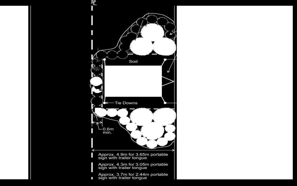
63 Figure