ESR-1545 Reissued February 1, 2014 This report is subject to renewal March 1, 2016.
|
|
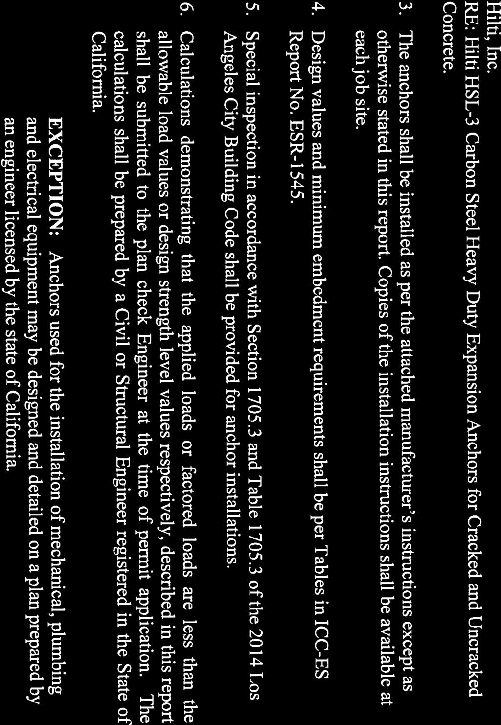
|
- Hope Rosalyn Foster
- 5 years ago
- Views:
Transcription


1
2
3
4 ICC-ES Evaluation Report ESR-1545 Reissued February 1, 014 This report is subject to renewal March 1, (800) (56) A Subsidiary of the International Code Council DIVISION: CONCRETE Section: Concrete Anchors DIVISION: METALS Section: Post-Installed Concrete Anchors REPORT HOLDER: HILTI, INC SOUTH 1 ND EAST AVENUE TULSA, OKLAHOMA (800) HiltiTechEng@us.hilti.com EVALUATION SUBJECT: HILTI HSL-3 CARBON STEEL HEAVY DUTY EXPANSION ANCHORS FOR CRACKED AND UNCRACKED CONCRETE 1.0 EVALUATION SCOPE Compliance with the following codes: 01, 009, 006 and 003 International Building Code (IBC) 01, 009, 006 and 003 International Residential Code (IRC) Property evaluated: Structural.0 USES The Hilti HSL-3 Heavy Duty Expansion Anchor is used to resist static, wind, and seismic tension and shear loads in cracked and uncracked normal-weight and sandlightweight concrete having a specified compressive strength,500 psi f c 8,500 psi (17. MPa f c 58.6 MPa). The Hilti HSL-3 anchors comply with Section 1909 of the 01 IBC, Section 191 of the 009 and 006 IBC, and Section 1913 of the 003 IBC. The anchor system is an alternative to cast-in-place anchors described in Section 1908 of the 01 IBC, Section 1911 of the 009 and 006 IBC and Section 191 of the 003 IBC. The anchors may also be used where an engineered design is submitted in accordance with Section R of the IRC. 3.0 DESCRIPTION 3.1 HSL-3 Carbon Steel Heavy Duty Sleeve Anchor: General: The Hilti HSL-3 Carbon Steel Heavy Duty Expansion Concrete Anchor, designated as the HSL-3, is a torque-set, sleeve-type mechanical expansion anchor. The HSL-3 is comprised of seven components which vary slightly according to anchor diameter, as shown in Figure 1 of this report. It is available in five head configurations, illustrated in Figure of this report. All carbon steel parts receive a minimum 5 m (0.000 inch) thick galvanized zinc plating. Dimensions and installation criteria are set forth in Tables 1 and of this report. Application of torque at the head of the anchor causes the cone to be drawn into the expansion sleeve. This in turn causes the sleeve to expand against the wall of the drilled hole. The ribs on the collapsible element prevent rotation of the sleeve and cone during application of torque. Application of the specified installation torque induces a tension force in the bolt that is equilibrated by a precompression force in the concrete acting through the component being fastened. Telescopic deformation of the collapsible element prevents buildup of precompression in the anchor sleeve in cases where the shear sleeve is in contact with the washer, and permits the closure of gaps between the work surface and the component being fastened. Application of tension loads that exceed the precompression force in the bolt will cause the cone to displace further into the expansion sleeve (follow-up expansion), generating additional expansion force HSL-3 (Bolt): The anchor consists of a stud bolt, steel washer, steel sleeve, collapsible plastic sleeve, steel expansion sleeve and steel cone. This anchor is available in carbon steel only. The material specifications are as follows: Bolt: Carbon steel per DIN EN ISO 898-1, Grade 8.8 Washer: Carbon steel per DIN EN Expansion cone: Carbon steel per DIN Expansion sleeve: Carbon steel, M8-M16 per DIN 10139, M0-M4 per DIN Steel sleeve: Carbon steel per DIN Collapsible sleeve: Acetal polyoxymethylene (POM) resin HSL-3-G (Stud): The anchor has the same components and material specifications as the HSL-3 (bolt) with the exception that the bolt is replaced by a threaded rod of carbon steel per DIN EN ISO Grade 8.8 and a nut of carbon steel per DIN 934 Grade 8. A screwdriver slot is provided on the exposed end of the threaded rod HSL-3-B (Torque-Indicator Bolt): The anchor has the same components and material specifications as the HSL-3 (bolt) with the addition of a torque cap nut that permits the proper setting of the anchor without a torque- ICC-ES Evaluation Reports are not to be construed as representing aesthetics or any other attributes not specifically addressed, nor are they to be construed as an endorsement of the subject of the report or a recommendation for its use. There is no warranty by ICC Evaluation Service, LLC, express or implied, as to any finding or other matter in this report, or as to any product covered by the report Copyright 014 Page 1 of 10 Deleted by the City of Los Angeles
5 ESR-1545 Most Widely Accepted and Trusted Page of 10 indicator wrench. The torque cap is zinc alloy complying with DIN A hexagonal nut is fastened to the bolt head by three countersunk rivets. When the anchor is tightened, the torque is transmitted to the cap. When the torque corresponding to the required anchor expansion is attained, the three countersunk rivets shear off. The torque cap nut breaks free exposing the permanent hex nut HSL-3-SH: The anchor has the same components and material specifications as the HSL-3 (bolt) with the exception that the bolt head is configured to accept a hexagonal Allen wrench HSL-3-SK: The anchor has the same components and material specifications as the HSL-3 (bolt) except that the bolt head is configured for countersunk applications, is configured to accept a hexagonal Allen wrench and is provided with a conical washer. The bolt is carbon steel per DIN ISO and DIN EN ISO 898-1, Grade Concrete: Normal-weight and sand-lightweight concrete must conform to Sections 1903 and 1905 of the IBC, as applicable. 4.0 DESIGN AND INSTALLATION 4.1 Strength Design: General: Design strength of anchors complying with the 01 and 003 IBC, and the 01 and 003 IRC, must be in accordance with ACI Appendix D and this report. Design strength of anchors complying with the 009 IBC and 009 IRC must be in accordance with ACI Appendix D and this report. Design strength of anchors complying with the 006 IBC and 006 IRC must be in accordance with ACI Appendix D and this report. Design parameters are based on the 01 IBC (ACI ) unless noted otherwise in Sections through of this report. The strength design of anchors must comply with ACI 318 D.4.1, except as required in ACI 318 D.3.3. Strength reduction factors, φ, as given in ACI D.4.3 must be used for load combinations calculated in accordance with Section of the IBC and Section 9. of ACI 318. Strength reduction factors, φ, as given in ACI D.4.4 must be used for load combinations calculated in accordance with ACI 318 Appendix C. The value of f c used in the calculations must be limited to a maximum of 8,000 psi (55. MPa), in accordance with ACI D.3.7. A design example according to the 01 IBC is given in Figure 4 of this report Requirements for Static Steel Strength in Tension, N sa : The static steel strength in tension must be calculated in accordance with ACI 318 D The values for N sa are given in Table 3 of this report. Strength reduction factors, φ, corresponding to ductile steel elements may be used for the HSL Requirements for Static Concrete Breakout Strength in Tension, N cb and N cbg : The nominal concrete breakout strength of a single anchor or group of anchors in tension, N cb and N cbg, respectively must be calculated in accordance with ACI 318 D.5., with modifications as described in this section. The basic concrete breakout strength of a single anchor in tension, N b, must be calculated in accordance with ACI 318 D.5.. using the values of h ef,min and k cr as given in Table 3 of this report in lieu of h ef and k c, respectively. The nominal concrete breakout strength in tension, in regions where analysis indicates no cracking in accordance with ACI 318 D.5..6, must be calculated with c,n = 1.0 and using the value of k uncr as given in Table 3 of this report Requirements for Static Pullout Strength in Tension, N pn : The nominal pullout strength of a single anchor, in accordance with ACI 318 D and D.5.3. in cracked and uncracked concrete, N p,cr and N p,uncr, respectively, is given in Table 3 of this report. In lieu of ACI 318 D.5.3.6, c,p = 1.0 for all design cases. In accordance with ACI 318 D.5.3, the nominal pullout strength in cracked concrete can be adjusted by calculation according to the following equation: (lb, psi) (Eq-1) (N, MPa) In regions where analysis indicates no cracking in accordance with ACI 318 D.5.3.6, the nominal pullout strength in tension must be calculated according to the following equation: (lb, psi) (Eq-) (N, MPa) Where values for N p,cr or N p,uncr are not provided in Table 3, the pullout strength in tension need not be evaluated Requirements for Static Steel Strength in Shear, V sa : The nominal steel strength in shear, V sa, in accordance with ACI 318 D.6.1., is given in Table 3 of this report must be used in lieu of the value derived by calculation from ACI , Eq D-9. Strength reduction factors, φ, corresponding to ductile steel elements may be used for the HSL Requirements for Static Concrete Breakout Strength in Shear, V cb or V cbg : The nominal concrete breakout strength in shear of a single anchor or group of anchors, V cb or V cbg, respectively, must be calculated in accordance with ACI 318 D.6. with modifications as provided in this section. The basic concrete breakout strength of a single anchor in shear, V b, must be calculated in accordance with ACI 318 D.6.. using the values of l e and d a (d o ) given in Table 3 of this report Requirements for Static Concrete Pryout Strength in Shear, V cp or V cpg : The nominal static concrete pryout strength of a single anchor or group of anchors in shear, V cp or V cpg, must be calculated in accordance with ACI 318 D.6.3, modified by using the value of k cp provided in Table 3 of this report and the value of N cb or N cbg as calculated in accordance with Section of this report Requirements for Seismic Design: General: For load combinations including seismic, the design must be performed in accordance with ACI 318 D.3.3. For the 01 IBC, Section shall be omitted. Modifications to ACI 318 D.3.3 shall be applied under Section of the 009 IBC, Section of the 006 IBC, or the following, as applicable: CODE 003 IBC and 003 IRC Deleted by the City of Los Angeles ACI 318 D.3.3 SEISMIC REGION Moderate or high seismic risk CODE EQUIVALENT DESIGN Seismic Design Categories C, D, E, and F
6 ESR-1545 Most Widely Accepted and Trusted Page 3 of Seismic Tension: The nominal steel strength and the nominal concrete breakout strength for anchors in tension must be calculated according to ACI 318 D.5.1 and D.5., as described in Sections 4.1. and of this report. In accordance with ACI 318 D.5.3., the appropriate pullout strength in tension for seismic loads, N p,eq, described in Table 3 must be used in lieu of N p. The value of N p,eq may be adjusted by calculation for concrete strength in accordance with Eq-1 and Section whereby the value of N p,eq must be substituted for N p,cr and the value of 3,000 psi (0.7 MPa) must be substituted for the value of,500 psi (17. MPa) in the denominator. If no values for N p,eq are given in Table 3, the static design strength values govern Seismic Shear: The nominal concrete breakout strength and pryout strength for anchors in shear must be calculated according to ACI 318 D.6. and D.6.3, as described in Sections and of this report. In accordance with ACI 318 D.6.1., the appropriate value for nominal steel strength for seismic loads, V sa,eq described in Table 3 must be used in lieu of V sa Requirements for Interaction of Tensile and Shear Forces: For anchors or groups of anchors that are subject to the effects of combined tensile and shear forces, the design must be performed in accordance with ACI 318 D Requirements for Critical Edge Distance: In applications where c < c ac and supplemental reinforcement to control splitting of the concrete is not present, the concrete breakout strength in tension for uncracked concrete, calculated according to ACI 318 D.5., must be further multiplied by the factor cp,n as given by the following equation: c cp,n = c a c (Eq-3) where the factor cp,n need not be taken as less than 1.5 hef. For all other cases, cp,n = 1.0. Values for the c ac critical edge distance c ac must be taken from Table 4 of this report. The values c ac,a are valid for a member thickness h h min,a and the values c ac,b for h min,b h < h min,a Requirements for Minimum Member Thickness, Minimum Anchor Spacing and Minimum Edge Distance: In lieu of ACI 318 D.8.1 and D.8.3, values of s min and c min as given in Table 4 of this report must be used. In lieu of ACI 318 D.8.5, minimum member thicknesses h min as given in Table 4 of this report must be used. Additional combinations for minimum edge distance c min and spacing s min may be derived by linear interpolation between the given boundary values. (See example in Table 4 of this report.) Sand-lightweight Concrete: For ACI and ACI , when anchors are used in sand-lightweight concrete, the modification factor a or, respectively, for concrete breakout strength must be taken as 0.6 in lieu of ACI D.3.6 (01 IBC) or ACI D.3.4 (009 IBC). In addition the pullout strength N p,cr, N p,uncr and N p,eq must be multiplied by 0.6, as applicable. For ACI , the values N b, N p,cr, N p,uncr,n p,eq and V b determined in accordance with this report must be multiplied by 0.6, in lieu of ACI 318 D Allowable Stress Design (ASD): General: 4..1 Design values for use with allowable stress design load combinations calculated in accordance with Section of the IBC shall be established as follows: φn T n allowable,asd = (Eq-4) α φv V n allowable,asd = (Eq-5) α where T allowable, ASD = Allowable tension load (lbf or kn) V allowable, ASD = Allowable shear load (lbf or kn) N n = Lowest design strength of an anchor or anchor group in tension as determined in accordance with ACI 318 Appendix D, Section 4.1 of this report and 009 IBC Section or 006 IBC Section , as applicable. V n = Lowest design strength of an anchor or anchor group in shear as determined in accordance with ACI 318 Appendix D Section 4.1 of this report and 009 IBC Section or 006 IBC Section , as applicable. = Conversion factor calculated as a weighted average of the load factors for the controlling load combination. In addition, shall include all applicable factors to account for nonductile failure modes and required over-strength. The requirements for member thickness, edge distance and spacing, described in this report, must apply. An example of allowable stress design values for illustrative purposes in shown in Table Requirements for Interaction of Tensile and Shear Forces: The interaction must be calculated and consistent with ACI 318 D.7 as follows: For shear loads V applied 0.V allowable,asd, the full allowable load in tension T allowable,asd may be taken. For tension loads T appplied 0.T allowable,asd, the full allowable load in shear V allowable,asd may be taken. For all other cases: Installation: 1. (Eq-6) Installation parameters are provided in Tables 1 and and in Figure 3 of this report. Anchors must be installed per the manufacturer s published instructions and this report. Anchor locations must comply with this report and the plans and specifications approved by the code official. Anchors must be installed in holes drilled into concrete using carbide-tipped drill bits complying with ANSI B Prior to anchor installation, the dust and debris must be removed from the predrilled hole in accordance with the manufacturer s published instructions. The nut must be tightened against the washer until the torque values, T inst, specified in Table are achieved.
7 ESR-1545 Most Widely Accepted and Trusted Page 4 of Special Inspection: Periodic special inspection is required, in accordance with Section of the 01 IBC, Section of the 009 IBC or Section of the 006 and 003 IBC, as applicable. The special inspector must make periodic inspections during anchor installation to verify anchor type, anchor dimensions, concrete type, concrete compressive strength, hole dimensions, anchor spacing, edge distances, concrete thickness, anchor embedment, installation torque, and adherence to the manufacturer's published installation instructions. The special inspector must be present as often as required in accordance with the statement of special inspection. Under the IBC, additional requirements as set forth in Sections 1705, 1706 and 1707 must be observed, where applicable. 5.0 CONDITIONS OF USE The Hilti HSL-3 anchors described in this report comply with, or are suitable alternatives to what is specified in, those codes listed in Section 1.0 of this report, subject to the following conditions: 5.1 Anchor sizes, dimensions and minimum embedment depths are as set forth in the tables of this report. 5. The anchors must be installed in accordance with the manufacturer s published installation instructions and this report, in cracked and uncracked normal-weight and sand-lightweight concrete having a specified compressive strength of f c =,500 psi to 8,500 psi (17. MPa to 58.6 MPa). In case of conflict between this report and the manufacturer s instructions, this report governs. 5.3 The values of f c used for calculation purposes must not exceed 8,000 psi (55.1 MPa). 5.4 Strength design values are established in accordance with Section 4.1 of this report. 5.5 Allowable stress design values are established in accordance with Section 4. of this report. 5.6 Anchor spacing and edge distance as well as minimum member thickness must comply with Table 4 of this report. 5.7 Prior to installation, calculations and details demonstrating compliance with this report must be submitted to the code official. The calculations and details must be prepared by a registered design professional where required by the statues of the jurisdiction in which the project is to be constructed. 5.8 Since an ICC-ES acceptance criteria for evaluating data to determine the performance of expansion anchors subjected to fatigue or shock loading is unavailable at this time, the use of these anchors under such conditions is beyond the scope of this report. 5.9 Anchors may be installed in regions of concrete where cracking has occurred or where analysis indicates cracking may occur (f t > f r ), subject to the conditions of this report Anchors may be used to resist short-term loading due to wind or seismic forces, subject to the conditions of this report Where not otherwise prohibited in the code, anchors are permitted for use with fire-resistance-rated construction provided that at least one of the following conditions is fulfilled: Anchors are used to resist wind or seismic forces only. Anchors that support a fire-resistance-rated envelope or a fire-resistance-rated membrane, are protected by approved fire-resistance-rated materials, or have been evaluated for resistance to fire exposure in accordance with recognized standards. Anchors are used to support nonstructural elements. 5.1 Use of zinc-coated carbon steel anchors is limited to dry, interior locations Special inspection must be provided in accordance with Section 4.4 of this report Anchors are manufactured for Hilti, Inc., under an approved quality control program with inspections by ICC-ES. 6.0 EVIDENCE SUBMITTED Data in accordance with the ICC-ES Acceptance Criteria for Mechanical Anchors in Concrete Elements (AC193), dated March IDENTIFICATION The anchors are identified by packaging labeled with the evaluation report holder s name (Hilti, Inc.) and address, anchor name, anchor size, evaluation report number (ICC-ES ESR-1545). The anchors have the letters HSL-3 and the anchor size embossed on the sleeve. Deleted by the City of Los Angeles
 Max. thickness of fastened part, t, corresponding to anchor length options 4 d s 1 3 min. max. t washer M8 0 40 5 < t 00 1 11.9 1.0 3.0 15. 19.0 14.0.0 M10 0 40 5 < t 00 1 14.")
8 ESR-1545 Most Widely Accepted and Trusted Page 5 of 10 ANCHOR VERSION (see Fig.) HSL-3 (bolt) HSL-3-G HSL-3 (bolt) HSL-3-G HSL-3-B HSL-3 (bolt) HSL-3-B Nom. bolt dia. TABLE 1 ANCHOR DIMENSIONAL CHARACTERISTICS (mm) Max. thickness of fastened part, t, corresponding to anchor length options 4 d s 1 3 min. max. t washer M < t M < t M < t M < t M < t M < t HSL-3-SH M M M HSL-3-SK M M M For pound-inch units: 1 mm = inches. 1 custom anchor lengths bolt version shown t ds l 1 l l 3 l 4 t washer t For determination of required hole depth: h hole,actual = h hole + t - t pl tpl hef,min hhole,actual See Tables and 3 for values of h hole and h ef,min. Illustration of Anchor Dimensional Characteristics
 (3.15) (3.54) (4.13) (4.9) (6.10) (7.09) mm 80 90 105 15 155 180 HSL-3-SH h hole mm 85 95 110 (in.) (3.35) (3.74) (4.")
 being fastened and concrete surface Washer diameter HSL-3, HSL-3-G, HSL-3-B - mm 4 5 8 9 1 16 (in.) (0.16) (0.0) (0.31) (0.35) (0.47) (0.63) d w (in.) (0.79) (0.98) (1.")
9 ESR-1545 Most Widely Accepted and Trusted Page 6 of 10 TABLE SETTING INFORMATION Nominal anchor diameter Parameters Symbol Units M8 M10 M1 M16 M0 M4 Nominal drill bit diameter 1 d bit mm Minimum hole depth HSL-3, HSL-3-G, HSL-3-B, HSL-3-SK h hole (in.) (3.15) (3.54) (4.13) (4.9) (6.10) (7.09) mm HSL-3-SH h hole mm (in.) (3.35) (3.74) (4.33) Clearance hole diameter in part being fastened d h mm (in.) (0.55) (0.67) (0.79) (1.0) (1.) (1.38) Max. cumulative gap between part(s) being fastened and concrete surface Washer diameter HSL-3, HSL-3-G, HSL-3-B - mm (in.) (0.16) (0.0) (0.31) (0.35) (0.47) (0.63) d w (in.) (0.79) (0.98) (1.18) (1.57) (1.77) (1.97) mm Installation torque HSL-3 T inst Nm (ft-lb) (18) (37) (59) (89) (148) (185) Wrench size HSL-3, HSL-3-G - mm Wrench size HSL-3-B - mm Installation torque HSL-3-G T inst Nm (ft-lb) (15) (6) (44) (59) (118) Allen wrench size for HSL-3-SH - mm Installation torque HSL-3-SH T inst Nm (ft-lb) (15) (6) (44) Allen wrench size for HSL-3-SK - mm Installation torque HSL-3-SK T inst Nm (ft-lb) (18) (37) (59) Diameter of countersunk hole HSL-3-SK d sk mm (in.) (0.89) (1.00) (1.9) For pound-inch units: 1 mm = inches, 1 Nm = ft-lbf. 1 Use metric bits only. Step 1: Using the correct diameter metric bit, drill hole to minimum required hole depth or deeper. Step 3: Using a hammer, tap the anchor through the part being fastened into the drilled hole until the washer is in contact with the fastened part. Do not expand anchor by hand prior to installation. Step : Remove drilling debris with a blowout bulb or with compressed air. Step 4: Using a torque wrench, apply the specified installation torque. HSL- 3-B does not require use of a torque wrench. Installation Instructions
10 ESR-1545 Most Widely Accepted and Trusted Page 7 of 10 Design parameter Symbol Units TABLE 3 DESIGN INFORMATION Nominal anchor diameter M8 M10 M1 M16 M0 M4 Anchor O.D. d a (d o ) 9 in mm Effective min. embedment depth 1 h ef,min mm in Anchor category 1, or Strength reduction factor for tension, steel failure modes 3 φ Strength reduction factor for shear, steel failure modes 3 φ Strength reduction factor for tension, φ Cond.A 0.75 concrete failure modes 3 Cond.B 0.65 Strength reduction factor for shear, Cond.A 0.75 concrete failure modes φ 3 Cond.B 0.70 Yield strength of anchor steel f ya lb/in 9,800 Ultimate strength of anchor steel f uta lb/in 116,000 Tensile stress area A se in Steel strength in tension N sa lb 6,61 10,440 15,196 8,188 44,080 63,45 Effectiveness factor uncracked concrete k uncr Effectiveness factor cracked concrete 4 k cr Modification factor for cracked and uncracked concrete 5 C,N Pullout strength uncracked concrete 6 N p,uncr lb 4,04 NA NA NA NA NA Pullout strength cracked concrete 6 N p,cr lb,810 4,496 NA NA NA NA Steel strength in shear HSL-3,-B,-SH,-SK V sa lb 7,39 10,9 14,75 6,707 39,51 45,951 Steel strength in shear HSL-3-G V sa lb 6,070 8,385 1,16,683 33,159 Coefficient for pryout strength k cp Load bearing length of anchor in shear e mm in Tension pullout strength seismic 7 N p,eq lb NA NA NA NA NA 14,30 Steel strength in shear, seismic 7 HSL-3,-B,-SH,-SK Steel strength in shear, seismic 7 HSL-3-G Axial stiffness in service load range 8 V sa,eq lb 4,609 8,453 11,89 4,796 9,135 38,173 lb 3,777 6,94 9,84 1,065 4,459 uncracked β concrete uncr ³ lb/in. cracked β concrete cr For SI: 1 inch = 5.4 mm, 1 lbf = 4.45 N, 1 psi = MPa. For pound-inch units: 1 mm = inches. 1 See Table 1. See ACI D For use with the load combinations of ACI 318 Section 9. or IBC Section Condition B applies where supplementary reinforcement in conformance with ACI Section D.4.3 is not provided, or where pull-out or pry out strength governs. For cases where the presence of supplementary reinforcement can be verified, the strength reduction factors associated with Condition A may be used. 4 See ACI D See ACI D NA (not applicable) denotes that this value does not control for design. See Section of this report. 7 NA (not applicable) denotes that this value does not control for design. See Section of this report. 8 Minimum axial stiffness values, maximum values may be 3 times larger (e.g., due to high-strength concrete). 9 The notation in parentheses is for the 006 IBC.
11 ESR-1545 Most Widely Accepted and Trusted Page 8 of 10 TABLE 4 EDGE DISTANCE, SPACING AND MEMBER THICKNESS REQUIREMENTS 1, Case Dimensional parameter Symbol Units Nominal anchor diameter M8 M10 M1 M16 M0 M4 A Minimum concrete thickness h min,a (mm) (10) (140) (160) (00) (50) (300) in. 4 3 / / 6 1 / / / / 8 A Critical edge distance c ac,a in. 4 3 / / / / / / 8 (mm) (110) (110) (10) (150) (5) (5) A Minimum edge distance 3 c min,aa in. 3 / 8 3 / / 4 3 / / 8 (mm) (60) (70) (90) (10) (15) (150) A Minimum anchor spacing 3 s min,aa in. 5 1 / 9 1 / / / / 8 (mm) (140) (40) (80) (30) (350) (300) A Minimum edge distance 3 c min,ab in. 3 3 / / / / / 4 (mm) (85) (15) (155) (00) (10) (10) A Minimum anchor spacing 3 s min,ab in. 3 / 8 3 / / / 8 (mm) (60) (70) (80) (100) (15) (150) B Minimum concrete thickness 4 h min,b in. 4 3 / / / / / 8 7 / 8 (mm) (110) (10) (135) (160) (190) (5) B Critical edge distance c ac,b in. 5 7 / / / / / / 4 (mm) (150) (175) (00) (50) (31.5) (375) B Minimum edge distance 3 c min,ba in. 3 / / 4 3 / / / / 8 (mm) (60) (90) (110) (160) (00) (5) B Minimum anchor spacing 3 s min,ba in / / / 4 15 (mm) (180) (60) (30) (380) (400) (380) B Minimum edge distance 3 c min,bb in / / / / / 8 (mm) (100) (160) (00) (70) (300) (30) B Minimum anchor spacing 3 s min,bb For pound-inch units: 1 mm = inches. in. 3 / 8 3 / / / 8 (mm) (60) (70) (80) (100) (15) (150) 1 See Section of this report. See Section of this report. 3 Denotes admissible combinations of h min, c cr, c min and s min. For example, h min,a + c cr,a + c min,aa + s min,aa or h min,a + c cr,a + c min,ab + s min,ab are admissible, but h min,a + c cr,b + c min,ab + s min,bb is not. However, other admissible combinations for minimum edge distance c min and spacing s min for h min,a or h min,b may be derived by linear interpolation between boundary values (see example for h min,a below). 4 For the HSL-3-SH M8, M10 and M1 diameters, the minimum slab thickness h min,b must be increased by 5 mm ( 3 / 16 "). Example of allowable interpolation of minimum edge distance and minimum spacing s design c design spacing s s design c min,aa ;s min,aa h min,a c min,ab ;s min,ab h h min,a c design edge distance c Example of allowable interpolation of minimum edge distance and minimum spacing
 mm inches f c = 500 psi M8 60.36 1,846 M10 70.76,417 M1 80 3.15,946 M16 100 3.94 4,1 M0 15 4.9 5,751 M4 150 5.91 7,57 1 Single anchor with static tension load only.")
12 ESR-1545 Most Widely Accepted and Trusted Page 9 of 10 TABLE 5 EXAMPLE ALLOWABLE STRESS DESIGN VALUES FOR ILLUSTRATIVE PURPOSES 1,,3,4,5,6,7,8,9,10 Nominal Anchor Diameter Effective Embedment Allowable Tension (lbs) mm inches f c = 500 psi M ,846 M ,417 M ,946 M ,1 M ,751 M ,57 1 Single anchor with static tension load only. Concrete determined to remain uncracked for the life of the anchorage. 3 Load combinations from ACI 318 Section 9. (no seismic loading). 4 30% dead load and 70% live load, controlling load combination 1.D + 1.6L 5 Calculation of weighted average for = = f c =,500 psi (normal weight concrete). 7 c a1 = c a c ac 8 h h min 9 Values are for Condition B where supplementary reinforcement in accordance with ACI D.4.3 is not provided. 10 φ factor is 0.65 FIGURE 1 HSL-3 (BOLT VERSION SHOWN) FIGURE HSL-3 HEAD CONFIGURATIONS FIGURE 3 CORRECT INSTALLATION OF HSL-3
 Assume uncracked normal-weight concrete.")
13 ESR-1545 Most Widely Accepted and Trusted Page 10 of 10 Given: Two HSL-3 M10 anchors under static tension load as shown. h ef =.76 in. Normal weight concrete with f ' c = 3,000 psi. No supplementary reinforcement. Condition B (ACI D.4.3 c) Assume uncracked normal-weight concrete..76 Needed: Using Allowable Stress Design (ASD) Calculate the allowable tension load for this configuration. Calculation per ACI Appendix D and this report. Code Ref. Report Ref. Step 1. Calculate steel strength of anchor in tension D.5.1. Nsa = nase,nfuta = x x116,000 = 0, 880 lb Table 3 Step. Calculate steel capacity Step 3. Calculate concrete breakout strength of anchor in tension N ANc = ec,n ed,n c,n cp,nn cbg b ANco Step 4. Verify minimum spacing and edge distance: Table 4 Case A: h min = 5-1/ in. < 6 in. okay slope = = For c s min min = 4 in. = [(4 -.75)(-3.0)] = 5.75 in. < 6 in. okay N = 0.75 x 0,880 = 15,600 lb D.4.3 a Table 3 sa s min 5.75 (.75, 9.5) 4 (5,.75) c min D D.8 Table 3 Table 4 Step 5. Calculate A Nco and A Nc for the anchorage: ANco = 9hef = 9(.76) A = ( 1.5hef + c)(3hef + s) = [1.5(.76) + 4][3(.76) + 6] = 116. in < A Nco Nc = 68.6 in okay D.5..1 Table 3 ' 1.5 Step 6. Calculate Nb = kuncrλa fc hef = 4 (1.0) 3,000(.76) = 6, 07 lb D.5.. Table 3 ' Step 7. Modification factor for eccentricity no eccentricity e D N ec, N Step 8. Modification factor for edge 1.5h ef = 1.5(.76) = 4.13 in.> c ed, N must be 4 calculated: ed, N = = (.76 ) Step 9. Modification factor for cracked concrete, k = 4 used in D.5.. (see c, N 1.0 Step10) D.5..5 Table 3 D.5..6 Table 3 max c 1.5 hef 1.5(.76) Step 10. Splitting Modification factor cp, N = c = = ac D.5..7 Table 4 Step 11. Calculate Step 1. Check pullout strength in Table Ncbg = x 1.0 x 0.99 x 1.0 x0.94x6,07 = 9,500 lb D N p, uncr does not govern D Table 3 Step 13. N cbg = 0.65x9,500 = 6,175 lb< N s N cbg controls D.4.3 c Table 3 Step 14. To convert to ASD, assume U = 1.D + 1.6L: T allow = = 4,17 lb FIGURE 4 EXAMPLE CALCULATION