EFFECT OF INFILL WALLS IN STRUCTURAL RESPONSE OF RC BUILDINGS BY NISAR ALI KHAN, PROF. DR. SAROSH HASHMAT LODI
|
|
|
- Helena Harrell
- 5 years ago
- Views:
Transcription

1 EFFECT OF INFILL WALLS IN STRUCTURAL RESPONSE OF RC BUILDINGS BY NISAR ALI KHAN, PROF. DR. SAROSH HASHMAT LODI 1
2 Contents 1) Introduction a - General Introduction b - Introduction about case study 2) Modeling a-system Level b- Component Level 3) (Case Study) of 2D Frame i. ii. System Level Response Component Level Response Comparison 5) Conclusion 4) 2D Frame 2
3 Introduction In the last decade the strong scientific and legislative introduced a revolution in design philosophy with respect to Earthquake Many existing buildings in the World, designed and constructed until the late 197 s without considering adequate earthquake provisions, constitute a significant potential risk (economical and social) for our society Assigned different tasks for structure engineer Vulnerability and seismic behavior of RC (Lesson from recent EQ s) Introducing of Tools and strategies (Monitoring and Evaluation) Introducing of some Experimental work on the assessment of Existing RC structures and Structural Components Discuss the potentialities and limitations of refined numerical models in the seismic response representation of old RC structures Introducing of possible seismic retrofitting solutions 3
4 Introduction But in spite of introduction of Modern codes, modern tools and techniques infill walls are still consider as non structural element The response of reinforced concrete buildings to earthquake loads can be substantially affected by the influence of infill walls Masonry infill in reinforced concrete buildings causes several undesirable effects under seismic loading: short-column effect, softstorey effect, torsion, and out-of-plane collapse. Hence, seismic codes tend to discourage such constructions in high seismic regions It is inadequate to assume that masonry infill panels are always beneficial in terms of structural response The contributions of infills to the building s seismic response can be positive or negative, depending on a series of phenomena and parameters such as, for example, relative stiffness and strength between the frames and the masonry walls In the study reported here, elaborates the effect of infill walls in the seismic response of reinforced concrete (RC) buildings 4

5 Introduction Of The Building (System Level) Plan Dimension of the Building Under Consideration 4. m 4. m 4.5 m 2. m 3.5 m 5
6 2-D Model (System Level) Potenza Italy, The PGA is.3g To investigate the influence of Infill walls we have 3 Types of models 1- Full infill walls 2- Soft-story 3- Bare Frame 6
7 is as follows: 1 for non-prestressed structures Modeling (Component Level) Columns Cross-Section Beams Cross-Section 7
8 Modeling (Component Level) Expected Elastic Modulus for Fair frame Material is; Efe = Ksi (29 Gpa) Concrete Compression Strength is; fc = 225 Psi (15.52 Mpa) Steel used in Columns and Beams are smooth Bars having yield strength is; fy = 23 Psi ( Mpa) 8
9 Modeling (Component Level) According to FEMA-356, Chapter-6, Table 6-7 & 6-8 Different Limit states for the nonlinear hinge should be define to capture the nonlinear behavior of RC structure s components Table 6-7 Use to define the Back Bone Curve s Properties and also to define the different limit state of the Beams Table 6-8 Use to define the Back Bone Curve s Properties and also to define the different limit state of the Columns 9 Table 6-7,8 of FEMA-356


10 Modeling (Component Level) According to FEMA-356 Chapter-6 Table 6-7 & 6-8 Different Limit states for the nonlinear hinge for Beams and Columns should be Define in the computer Program 1 Table 6-7,8 of FEMA-356
11 Modeling (Component Level) FEMA-356 Single Strut Compression Model Ae = ta and Vine = Anifvie Ani is the area of infill walls Expected Elastic Modulus for Fair Masonry infill walls in Compression is equal to E me = 55fm =33 Ksi, where fm is the compression strength of masonry equal to 6psi ( Mpa) Expected Shear Strength of Masonry is; fvie = 2 Psi (.1378 Mpa) 11 Table 7-1 of FEMA-356

12 Modeling (Component Level) FEMA-356 Single Strut Compression Model f'm Eme Linf tinf Ɵ Efe Ig Icol hinf ƛ1 hcol rinf a a in Ae in2 Kinf Linf/hinf Kip/in Compressive strength by ASCE-41/FEMA-356 Table 7-1 Elastic of modulus in compression of infill Length of infill Thickness of infill Diagonal angle of infill Elastic of modulus in compression of Frame Gross moment of inertia Column moment of inertia Height of infill Coefficient of infill Height of column I inclined length of infill Width of infill Width of infill Area of infill strut Horizontal stiffness of infill strut Ratio β = Vfre/Vine Axial strength of infill i.e. strut β Pno Psi Ksi in in Radian Ksi in4 in4 in in in Kip 12 Table 7-1 of FEMA-356
13 Modeling (Component Level) FEMA-356 Single Strut Compression Model replace the Infill walls a= a= a= As the Masonry is unreinforced so the infill model has no tendency to take Tension Force only has the ability to take Compression force. 13 Table 7-1 of FEMA-356
14 Modeling (Component Level) According to FEMA-356 a Nonlinear Hinge (Force Deformation Curve/Back Bone Curve) should be define to Capture the Nonlinear Behavior of the component of RC structure assigned for strut Model as shown in figure The Parameter used in calculation for strut properties to Replace the infill walls are shown in figure 14 Table 7-9 of FEMA-356
15 Modeling (Component Level) According to FEMA-356 Table 7-9 Different Limit states for the nonlinear hinge should be define 15 Table 7-9 of FEMA-356
16 Modeling (Component Level) The Back Bone Curve for the infill model should be define in the computer Model as shown in the Figure 16 Table 7-9 of FEMA-356
17 Linear Static FULL INFILLL 2-D FRAME 17

18 Linear Static (System Response) Base Shear By Linear Static is 25 KN 18
19 Linear Static (System Response) TABLE: Modal Participating Mass Ratios OutputCa StepTy StepNu se pe m Period Text Text Unitless Sec MODAL Mode MODAL Mode 2 MODAL Mode 3 UX UY UZ SumUX SumUY SumUZ RX RY RZ SumRX SumRY SumRZ Unitless Unitless Unitless Unitless Unitless Unitless Unitless Unitless Unitless Unitless Unitless Unitless

20 Linear Static (System Response) The First Three Effective Modes Shapes 2

21 Nonlinear Pushover (System Response) The maximum inter story Drift Ratio at the Performance level by Nonlinear is.235% 21
 The")


22 Nonlinear Pushover (System Response) The significance loss in strength is due to the damage in ground floor columns and infill at a time. 22

23 Nonlinear Pushover (System Response) The significance loss in strength is due to the damage in ground floor columns and infill at a time. 23
 having Roof")
24 Nonlinear Pushover (Components Response) The maximum Axial force in Left column is 1 KN having displacement 56 mm The maximum Axial force in the Right column is -58 KN(compression) having Roof displacement 56 mm 24

25 Nonlinear Pushover (Components Response) The maximum Shear Force in Left Column is 6.5 KN The maximum Shear Force in Right Column is 37 KN 25

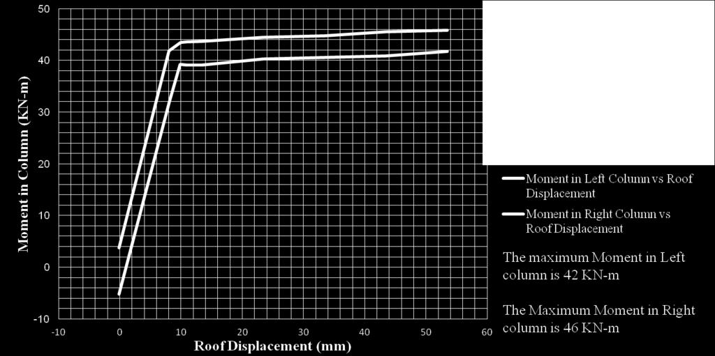
26 Nonlinear Pushover (Components Response) The Maximum Moment at the Left side Column is 14.5 KN-m The maximum Moment at the Right Hand side column is 55.5 KN-m 26
 this")


27 Nonlinear Pushover (Components Response) this infill take maximum force -312 KN and then it fails at 56 mm Displacement which cause the over all failure of the structure. 27
 Contribution of Infills")


28 Nonlinear Pushover (Components Response) Contribution of Infills and columns in taking shear Force at The Ground story The Circle one is the force taken by infills at 11th step and then it fails at next step, because of this failure the Pushover Curve Drops Sudden as shown in figure 28
29 Nonlinear Pushover (Components Response) Contribution of Infill and columns in taking shear Force at The 1st story 29

30 Nonlinear Pushover (Components Response) Contribution of Infill and columns in taking shear Force at The Last story 3
 The")

31 Use of Pushover Curve (ATC-4) (System Response) The performance point is at 518KN Base shear at displacement 16 mm 31
32 Linear Static SOFT STORY INFILLL 2-D FRAME 32
33 Linear Static (System Response) TABLE: Modal Participating Mass Ratios OutputC StepTy StepNu ase pe m Period Text Text Unitless Sec UX UY UZ SumU SumU X Y SumUZ RX RY RZ SumR SumR X Y SumRZ Unitless Unitless Unitless Unitless Unitless Unitless Unitless Unitless Unitless Unitless Unitless Unitless MODAL Mode MODAL Mode

34 Linear Static (System Response) The First Two Effective Modes Shapes 34

35 Nonlinear Pushover (System Response) The maximum inter story Drift Ratio at the Performance level by Nonlinear is 1.7% 35

36 Nonlinear Pushover (System Response) The structure collapse at 9th step of push load case at Base Shear 126 KN having displacement 53 mm because of the columns failure at the ground story level. 36
 ground story level.")
37 Nonlinear Pushover (System Response) The structure collapse having Base Shear 126 KN and displacement 53 mm because of the columns failure at the (Soft Story) ground story level. 37

38 Nonlinear Pushover (Components Response) The maximum axial force in Left column is -264 KN The Maximum Axial Force in Right column is -32 KN 38

39 Nonlinear Pushover (Components Response) The maximum Shear Force in Left Column is KN The Maximum Shear Force in Right Column is 3.5 KN 39

40 Nonlinear Pushover (Components Response) 4
41 Nonlinear Pushover (Components Response) Contribution of Infill and columns in taking shear Force at The 1st story, the infill do not fail but the global failure of the frame is due to the soft story columns failure 41
42 Nonlinear Pushover (Components Response) Contribution of Infill and columns in taking shear Force at The last story 42
 The")

43 Use of Pushover Curve (ATC-4) (System Response) The performance point is at 125 KN Base Shear having Displacement 41 mm 43
44 Linear Static BARE FRAMEE 44
45 Linear Static (System Response) TABLE: Modal Participating Mass Ratios OutputCa StepTy StepNu se pe m Period Sec UX UY UZ Unitless Unitless Unitless SumUX SumU Y SumUZ Unitless Unitle ss Unitless Unitless Unitless Unitless Unitless Unitless Unitless RX RY RZ SumRX SumRY SumRZ Text Text Unitless MODAL Mode E E MODAL Mode MODAL Mode E

46 Linear Static (System Response) The First Three Effective Modes Shapes 46

47 Nonlinear Pushover (System Response) The Max. inter story Drift Ratio at the Performance level by Nonlinear is 1.5% 47

48 Nonlinear Pushover (System Response) The final point of the structure is at 118 KN Base Shear having displacement 1 mm 48

49 Nonlinear Pushover (System Response) The final point of the structure is at 118 KN Base Shear having displacement 1 mm The Global failure is Due to The failure of columns at the ground and first floor fails 49

50 Nonlinear Pushover (Components Response) 5

51 Nonlinear Pushover (Components Response) The Maximum Shear Force in Left Column is 23.5 KN The Maximum Shear Force in Right Column is 25 KN 51

52 Nonlinear Pushover (Components Response) 52
 The")

53 Use of Pushover Curve (ATC-4) (System Response) The performance Point is at 116 KN Base Shear having displacement 47 mm 53
 The three Frames")

54 Nonlinear Pushover (System Response) Base Shear (KN) The three Frames Pushover and Demand Curves are shown together with their performance Points and stiffness 54
55 COMPARISON FULL INFILL FRAME The fundamental mode s period is.38 sec Max IDR is.235% Relative Displacement increase linearly has Range 1mm Stiffness is 55 KN/mm The Performance Point according to ATC-4 Capacity Spectrum method is at 16 mm displacement having Base Shear 518 KN Target Displacement according to FEAM-356 Coefficient method is 95.3 mm Global Ductility is 2.8 and failure of Infill and Columns Cause the overall Collapse mechanism. (COMPARISON BETWEEN INFILL AND BARE FRAME) 2- D (SOFT STORY FRAME) BARE FRAME The fundamental mode s period is.72 sec Max IDR is 1.7% Because of the presence of infill at the 1st and last story the floors do not displace so much relative to each other but the Ground Floor displace abruptly relative to the First Floor having variation about 14 times Stiffness is 12 KN/mm The Performance Point according to ATC-4 Capacity Spectrum method is at 41 mm displacement having Base Shear 125 KN Target Displacement according to FEAM-356 Coefficient method is 117 mm Global Ductility is 5.4 failure of Columns at Ground Story Cause the overall Collapse mechanism. The fundamental mode s period is.9 sec Max IDR is 1.5% The Ground and first floors Displace relative to each other having variation from 1 mm to 16.5 mm Stiffness is 71 KN/mm The Performance Point according to ATC-4 Capacity Spectrum method is at 47 mm displacement having Base Shear 116 KN Target Displacement according to FEAM-356 Coefficient method is 16 mm Global Ductility is 9.6 failure of Columns and Beams Cause the overall Collapse mechanism. 55
56 DESIGN RECOMENDATION The infill walls has great influence in global as well as local Response of the structure, so infill walls should consider during design new building and also evaluation and Retrofitting the existing buildings. Great computational modeling should perform while evaluating the existing infilled RC Structures. 56
57 CONCLUSION URM infill walls have a significant role in the strength and ductility of RC frame structures and should be considered in both analysis and design. Globally, these walls make the structure significantly stiffer, reduce the natural period of the structure, and increase the damping coefficient Masonry infill walls have a complex behavior due to the properties of their materials and to the interaction mechanisms with the surrounding frame..the performance of fully masonry infill walls Frames both in 2D and 3D analysis was significantly superior to that of bare frames and soft storey frames. The proposed macro-model can be a useful tool in the development and calibration of simplified rules for the analysis of infilled frame structures under horizontal loadings. 57
58 SPECIAL THANKS 58

59 THANKYOU FOR YOUR ATTENTION 59