UNITS CERTIFICATION. Test file: J.I. 1Z3A2.AM Per FMRC Standard 4471
|
|
|
- Elaine Patterson
- 5 years ago
- Views:
Transcription
1
.")
2 2 5/8" (67) 1 3/4 (44) 1 3/4 (44) 2 11/16" (68) 7/8" (22) 15/16" (24) 1 1/2" (38) 2 3/4" (70) 15 1/2" (394) 18 1/2" (470) 24" (610) 1 1/2" (38) 2 3/4" (70) UNITS Dimensions and sizes in this Manual are noted in Imperial followed by Metric in brackets. The Metric units are millimeters u/n. For example: the Standing Seam Roof Panel has a width of 24 (610). CERTIFICATION To ensure that the Behlen system will meet the demands of its application requirements, it has been tested and certified by Factory Mutual. The Behlen Roof System carries a Factory Mutual Class 1-SH Hail Rating and a 1-60 Fire Resistance and Wind Uplift rating. Appropriate construction information can be obtained in the Factory Mutual Approval Guide, Building Materials Section. Test file: J.I. 1Z3A2.AM Per FMRC Standard 4471
3 PREFACE 1 PREFACE The recommendations and application details contained in this manual illustrate the installation of the Behlen Standing Seam Roof System under standard conditions. Because of variations possible with any building, a careful study of the Building Erection Drawings is essential. Custom layout, details, and parts may be required. In case of disagreement between this Manual and the Erection Drawings, the Erection Drawings shall govern. Always follow all Building Codes applicable to the building area. All Building and Safety Regulations should be strictly adhered to. The General Contractor and/or Erector is solely responsible for accurate, good quality workmanship in erecting the building in accordance with the Behlen Drawings and Details and Industry Standards pertaining to proper erection, including the proper use of temporary bracing. Behlen Industries is not responsible for errors, omissions, or damages incurred in the erection of the components shown in the Drawings or Details, nor for the inspection of erected components to determine same. Contact Behlen Industries if there are any questions regarding proper installation techniques. Installation of the Roof System is to be done by experienced, qualified erectors. Installers are expected to be familiar with the contents of this manual, the Building Erection Drawings, and the Behlen Standard Detail Book. INSTALLATION FOR LONG-TERM PERFORMANCE Always use accessories that are compatible with the Galvalume roof. Fasteners and flashings should always be made from material designed to last as long as the roof. Beware of installing a galvanized component where rainwater will drain onto it from a Galvalume component. The resulting chemical reaction will corrode the galvanized component in short order. When installing fiberglass blanket insulation, carefully seal all vapor barrier seams, penetrations, and tears to prevent condensation of water on the underside of the roof. Always ensure that no insulation is left exposed where it can absorb water from outside the building. Condensation and saturated insulation can corrode the roof from the inside out. During installation, and immediately after, the panels must be swept clean to remove construction debris. Unused fasteners, metal filings, pop-rivet stems and pieces of flashings will rust quickly. Not only will unsightly stains be left on the roof, but also the Galvalume coating will sacrifice itself and compromise the panel. Use caution when installing rooftop units. Wood, especially treated, should never be installed or left on the roof, as draining or trapped water will react with the metal roof. Condensate from air conditioning units must never be allowed to drain directly onto the roof. Dissolved copper from the condensation coils can cause rapid corrosion.
4 TABLE OF CONTENTS 2 TABLE OF CONTENTS CERTIFICATION... 2 PREFACE... 1 INSTALLATION FOR LONG-TERM PERFORMANCE... 1 SAFETY FIRST... 5 GRADE 50 PANEL PROPERTIES (IMPERIAL) MPa PANEL PROPERTIES (METRIC)... 7 STANDING SEAM ROOF PARTS... 8 SEALANTS... 8 SEALER CALCULATION... 9 STANDARD PARTS (IMPERIAL) STANDARD PARTS (METRIC) STANDARD PARTS & TOOLS STANDARD TRIMS (SUPPLIED IN 26 GAUGE U/N) TRIM SELECTION SPECIALTY FASTENERS ASSOCIATED FASTENERS SELF-DRILLING SCREW INSTALLATION EQUIPMENT INSTALLATION TECHNIQUE ON-SITE HANDLING PROPER TEMPORARY OUTDOOR STORAGE HANDLING PANEL BUNDLES LOADING PANELS ONTO ROOF PREPARATION ROOF GEOMETRY Corner-To-Corner Triangle Purlin / Joist Alignment and Stabilization START POINT AND DIRECTION OF INSTALLATION Endlap Notching Acceptable Start and End Locations PANEL LAYOUT (GENERAL) SEAMS EAVE RIDGE / HIGH EAVE ENDLAPS Panel Overhang Tolerance RAKE ANGLE INSTALLATION EAVE PLATE INSTALLATION TYPE... 32
5 TABLE OF CONTENTS 3 PROCEDURE PRIMARY EAVE TRIM INSTALLATION FIRST ROW OF SSR CLIPS INTALLATION TYPE LOCATION PROCEDURE METAL EAVE CLOSURE INSTALLATION STARTER PANEL INSTALLATION A) FULL WIDTH STARTER PANEL PROCEDURE B) FIELD MODIFIED STARTER PANEL PRODCEDURE PANEL ENDLAP INSTALLATION GENERAL PROCEDURE ICE DAMMING PROTECTION HAND CRIMPING PROCEDURE STANDARD PANEL INSTALLATION PANEL TERMINATION A) FULL WIDTH TERMINATION PANEL INSTALLATION B) FIELD MODIFIED TERMINATION PANEL INSTALLATION PANEL SEAMING GENERAL BEHLEN 24 GAUGE PANEL SEAMER SPECIFICATIONS BEHLEN 22 GAUGE PANEL SEAMER SPECIFICATIONS STARTING PLATFORM MAINTENANCE ADJUSTMENT FOR SEAM TOLERANCES PANEL SEAMING PROCEDURE EAVE TRIM INSTALLATION GUTTER TRIM INSTALLATION END DAM INSTALLATION RAKE ZEE INSTALLATION GABLE TRIM GENERAL: GABLE TRIM INSTALLATION HIGH EAVE TRIM INSTALLATION GABLE CORNER BOX GENERAL A) GUTTER: B) EAVE TRIM: CENTER GABLE COVER GENERAL A) STANDARD CENTER GABLE COVER (554185): B) FIELD FABRICATED CENTER GABLE COVER SLIDING STEP DETAIL GENERAL INSTALLATION RIDGE CAP INSTALLATION... 83
6 TABLE OF CONTENTS 4 RIDGE CAP EXPANSION DETAIL INSTALLATION LEAN-TO HIGH EAVE DETAIL LEAN-TO HIGH EAVE INSTALLATION ROOF PENETRATIONS PIPE FLASHING INSTALLATION ROOF CURBS INDEX ERECTOR NOTES... 90
7 SAFETY 5 SAFETY FIRST SAFETY MUST BE MADE THE TOP PRIORITY ON ALL JOB SITES. Follow all applicable safety guidelines, both customary and statutory, to ensure worker safety. This manual illustrates the installation of the various components. It is up to the builder or erector to ensure that the installation is carried out safely. If following any of these instructions would endanger any worker(s), another method must be found. Do not use the roof panels as walking platforms. The unseamed panels will not support the weight of a person at the edge. Provide walking platforms for workers who must walk on the unseamed panels. Provide railings and safety lines for workers and see that they are used at all times. Exercise extreme caution near the roof edges and openings, including the ridge. Blanket insulation can offer a false sense of security. Stay alert to avoid stepping or leaning onto the insulation. Never step on an unsecured panel. Such panels can easily start sliding. Do not stand at the panel ends before they are seamed. Pay attention to the worksite. Do not tolerate tripping or falling hazards. Frost and dew can create an extremely hazardous surface. Do not step onto a frost-covered roof. The various components have sharp metal edges. Gloves and eye protection should be worn at all times. Conduct safety meetings regularly.
8 PANEL PROPERTIES 6 PHYSICAL PROPERTIES Base Thickness (in) Coated Thickness AZ165 (in) GRADE 50 PANEL PROPERTIES (IMPERIAL) Per Foot Width In Accordance with CSA Standard S Section Moment of Section Modulus Inertia Modulus Positive Positive Negative Bending (in 3 ) Bending (in 4 ) Bending (in 3 ) Moment of Inertia Negative Bending (in 4 ) Moment of Inertia Deflection (in 4 ) Weight (lbs/ft 2 ) Span (ft) LOAD TABLE Single-Span Base Steel Nominal Thickness (in) Maximum Specified Uniformly Distributed Load lb/ft 2 (psf) Two-Span Three-Span Base Steel Nominal Thickness Base Steel Nominal Thickness (in) (in) B D B D B D B D B D B D B D NOTES: 1) Properties and loads are based on Grade 50 steel with a minimum yield stress of 50,000 psi and a maximum factored stress of 45,000 psi. 2) Figures in row B indicate the load capacity based on strength. Strength capacity B should be checked against (Specified Live Load) + (0.833 x Specified Dead Load). 3) Figures in row D indicate the load capacity based on deflection of 1/240 th span. For allowable deflection of 1/180 th span, values in row D may be multiplied by 1.333, but capacity must not exceed the value in row B. Deflection capacity should be checked against Specified load(s). 4) Positive bending indicates top in compression. Negative bending indicates bottom in compression.
9 PANEL PROPERTIES 7 PHYSICAL PROPERTIES Base Thickness (mm) Coated Thickness AZ165 (mm) 345 MPa PANEL PROPERTIES (METRIC) Per Metre Width In Accordance with CSA Standard S Section Moment of Section Modulus Inertia Modulus Positive Positive Negative Bending Bending Bending (mm 3 x 10 3 ) (mm 4 x 10 3 ) (mm 3 x 10 3 ) Moment of Inertia Negative Bending (mm 4 x 10 3 ) Moment of Inertia Deflection (mm 4 x 10 3 ) Weight (kg/m 2 ) Span (mm) LOAD TABLE Single-Span Base Steel Nominal Thickness (mm) Maximum Specified Uniformly Distributed Load kn/m 2 (kpa) Two-Span Three-Span Base Steel Nominal Thickness Base Steel Nominal Thickness (mm) (mm) B D B D B D B D B D B D B D NOTES: 1) Properties and loads are based on Grade 345 steel with a minimum yield stress of 345 Mpa and a maximum factored stress of Mpa. 2) Figures in row B indicate the load capacity based on strength. Strength capacity B should be checked against (Specified Live Load) + (0.833 x Specified Dead Load). 3) Figures in row D indicate the load capacity based on deflection of 1/240 th span. For allowable deflection of 1/180 th span, values in row D may be multiplied by 1.333, but capacity must not exceed the value in row B. Deflection capacity should be checked against Specified load(s). 4) Positive bending indicates top in compression. Negative bending indicates bottom in compression.
10 STANDING SEAM ROOF PARTS 8 STANDING SEAM ROOF PARTS SEALANTS The sealants supplied and specified have been carefully chosen for their suitability to their application. Behlen Industries recommends that the highest quality non-skinning butyl, urethane or silicone polymer sealants be used to assure lasting performance on the roof. It is important that the sealants do not contain any acid residue, as it may react with the Galvalume finish. Clean all surfaces to be weather sealed. Remove all fabricating oils, moisture, ice, dust and dirt prior to application of mastics or sealant. NOTE: Joint preparation is key to sealant performance. All surfaces must be sound, clean, dry, and free of any oily residue. After applying an exposed bead of caulking, use a small spatula or similar tool to feather the edges of the bead to the base material. This will improve the seal and extend the life of the joint.
11 STANDING SEAM ROOF PARTS 9 SEALER CALCULATION *Note that the sealer for special details must be added to the quantities calculated in the table below. * STANDING SEAM ROOF SEALER COUNT LOCATION PLACEMENT CALCULATION QTY 1/8 x 1/2 (3 x 13) SEALER ( ) (30 (9144) ROLLS) GUTTER STRAPS Under Strap TOTAL LENGTH OF LOW EAVE x 0.6 EAVE CLOSURES Top Of Closure TOTAL LENGTH OF LOW EAVE x 0.5 GABLES T & B Of Rake Zee TOTAL LENGTH OF GABLES x 2 SLIDING STEP Rake Zee & Closures LENGTH OF SLIDING STEP x 4 High Wall Seams LENGTH OF SLIDING STEP x 1.67 Hip Flash & Closures LENGTH OF LEAN-TO CONN. x 3 High Wall Seams LENGTH OF LEAN-TO CONN. x 1.67 LEAN-TO HIGH EAVE HIGH EAVE Under Eave Trim LENGTH OF HIGH EAVE RIDGE Under Ridge Cap RIDGE LENGTH x 2 TOTAL 3/32 x 1 1/2 (2 x 38) MASTIC PAD (40 (12 192) ROLLS) LOW EAVE Under Panel TOTAL LENGTH OF LOW EAVE x 1.0 ENDLAPS Between Panels BUILDING LEN. x ROWS OF ENDLAPS x 1.11 HIGH EAVE Under End Dam LENGTH OF HIGH EAVE x 1.11 RIDGE Under End Dam BUILDING LENGTH x 2.22 TOTAL GUN GRADE MASTIC (995053) LEN. PER TUBE = 1/4 or 3/16 6 or 10 5 ) LOW EAVE Top Of Closure TOTAL LENGTH OF LOW EAVE x 0.5 Primary Trim Laps TOTAL LENGTH OF LOW EAVE x ENDLAPS End Of Panel BUILDING LEN. x ROWS OF ENDLAPS x 1.11 GABLE Rake Zee Laps TOTAL LENGTH OF GABLE x 0.05 HIGH End Dam LENGTH OF HIGH EAVE x 1.5 End Dam LENGTH OF RIDGE x 3.0 TOTAL SIKA TUBE CAULK (995051) LEN. PER TUBE= 1/4 or 3/16 6 or 10 5 ) LOW EAVE Face Of Male Rib TOTAL LENGTH OF LOW EAVE x 0.5 1/4:12(2.08:100) TOTAL LENGTH OF LOW EAVE x 10 1/2:12(4.17:100) TOTAL LENGTH OF LOW EAVE x 5 1:12(8.33:100) TOTAL LENGTH OF LOW EAVE x 2.5 Steeper TOTAL LENGTH OF LOW EAVE x 0.25 INSIDE TOP OF RIB ENDLAPS Panel Rib BUILDING LEN. x ROWS OF ENDLAPS x 1.11 SLIDING STEP Behind Hip Flash WALL WIDTH HIGH EAVE Inside Male Rib LENGTH OF HIGH EAVE x 0.25 RIDGE Inside Male Rib LENGTH OF RIDGE x 0.5 SSR CLIPS Under Tab # OF CLIPS / 3 (UNPERFORATED CLIPS ONLY) RIDGE CAP Expansion Detail RIDGE LENGTH x 0.05 LEAN-TO HI EAVE Ice Damming Protection LENGTH OF HIGH EAVE x 5 TOTAL POLYURETHANE CAULK (995056) LEN. PER TUBE= 1/4 or 3/16 6 or 10 5 ) GUTTERS Gutter Laps & End Caps GUTTER LEN. x END CAPS x 3.0 TOTAL
12 23 1/2" INDUSTRIES STANDING SEAM ROOF PARTS 10 STANDARD PARTS (IMPERIAL) 192" 120" 148" 4 1/2" 3" 4 1/2" /4" 90 1" 1 3/8" 1 3/8" 19 3/4" 4" 2" 13" 5 5/8" 9" 2 5/8" 3/4" 144" 144" 144" 1 1/4" 1 1/2" 1 1/2" 1 1/2" 1" 1/2" 2" 1/2" 2 1/4" 2 1/4" 120" 1" (TYP.) * 2 5/8" ALL HOLES ARE 1/4"Ø 2 5/8" 1 3/4" * 2 1/4" * * 2 3/4" /4"
13 STANDING SEAM ROOF PARTS 11 STANDARD PARTS (METRIC) RAKE ANGLE 1.90mm EAVE ANGLE 1.90mm BRACE/SAG ANGLES 2.65mm GUTTER HANGER STRAP 1.90mm ENDLAP PLATE (SSR) 1.21mm HIP FLASHING SUPPORT 0.76mm EAVE PLATE (SSR) 1.52mm EAVE PLATE (SSR) 1.52mm EAVE PLATE (SSR) 1.52mm RAKE Z (SSR) 0.61mm END DAM 1.21mm STANDING SEAM ROOF CLIP STANDING SEAM ROOF CLIP FLEXIBLE STANDING SEAM ROOF END CELL SSR CLOSURE BLOCK

14 STANDING SEAM ROOF PARTS 12 STANDARD PARTS & TOOLS
15 STANDING SEAM ROOF PARTS 13 STANDARD TRIMS (SUPPLIED IN 26 GAUGE U/N) 160 1/2" (13) 5" (127) COLOR EAVE TRIM /4" 95 5/8" 4" (102) /2" (191) " (102) 4" (102) COLOR GABLE COVER (SSR) HIGH EAVE 1/2" (12) /2" (191) 4" (102) /8" (3) 4" (102) 5/8" (16) 1" (25) S.S.R. GABLE COVER /2' COLOR COLOR 2 1/4" (57) " (203) 1 1/4" (32) 3/4" (19) COLOR 135 3" (76) 90 2 CREASE 3" (76) 3/4" 1/4" SEAM GABLE LOCK " (152) HIP FLASHING " (178) HIP FLASHING /4" (32) 4" (102) /8" (60) /16" (37) 4" (102) 1" (25) /2" (13) 5/8" (16) 1" (25) /16" (132) 1 7/16" (37) 3 15/16" (100) 1" (25) /2" (13) 13/16" (21) 1" (25) /8" (130) COLOR SIDE SSR EAVE TRIM /2" COLOR (140) FEMALE GUTTER (SSR) COLOR 5 7/16" (138) MALE GUTTER (SSR) /4" 6 7/8" (175) 1 9/16" (40) 9 13/16" (249) FINISH ROOF CAP(SSR) /2" (140) 2" /16" (103) 4" 1 1/2" (38) 1" (25) 1 1/2" (38) 6 7/8" (175) 1" (25) 6 7/8" (175) 1" (25) 1 1/4" (32) 3 7/8" (98) 5 5/16" (135) 4 15/16" (125) 3/4" (19) TYP. 1 1/4" (32) 3 7/8" (98) 5 5/16" (135) 4 15/16" (125) 3/4" (19) TYP. ALL BENDS DOWN 90 ALL BENDS UP 90 END CAP L.H. (SSR) END CAP R.H. (SRR) /16" (103) 7 1/2" (191) GABLE CORNER BOX STANDING SEAM ROOF PRIMARY EAVE TRIM (STANDING SEAM ROOF) CENTER GABLE COVER 24 GA. 1:
16 STANDING SEAM ROOF PARTS 14 TRIM SELECTION The following diagram indicates the general location of the various standard trims on a typical building. The Building Erection Drawings will indicate if any custom parts have been supplied, or if standard parts are to be use in non-typical locations. Refer to the body of this Manual for detailed installation instructions. RAKE ZEE PT# SSR END CELL PT# SSR ROOF CAP PT# SSR GABLE COVER PT# PANEL SUPPORT PT# RAKE ZEE PT# SSR CENTER GABLE COVER PT# (1:12) SSR END DAM PT# GABLE LOCK PT# GABLE CORNER BOX PT# HIP FLASHING PT# SSR HIP FLASHING PT# SSR END DAM PT# PRIMARY EAVE TRIM PT# SSR GABLE COVER PT# SSR END DAM PT# EAVE TRIM PT# PRIMARY EAVE TRIM PT# METAL EAVE CLOSURE PT# NOTE: 556XXX PT.#'S SHOWN ARE FOR STANDARD 26Ga. TRIMS. FOR 24Ga., USE 554XXX PT.#'S. CHECK MATERIAL AVAILABILITY. 3x4 DOWNSPOUT PT# x4 ELBOW PT# x3 ELBOW PT# " 4" FEMALE GUTTER PT# MALE GUTTER PT# END CAPS L.H. PT# R.H. PT# METAL EAVE CLOSURE PT#556369
17 STANDING SEAM ROOF PARTS 15 SPECIALTY FASTENERS 1/4-14 x 7/8" MAC LAP PT.# ST DRIVE: HEX HEAD - 5/16" WASHER: EPDM COATING: STAINLESS CAP 1, 2 USE: Fastening panel and trims to panel and trims on SSR Roofs. DRILL POINT: #1 MAX MATERIAL: 0.320" (8.1) DRILL/TAP CAPACITY: 0.03" " ( ) 1/4-14 x 1 1/4" SD (Clip Screw) *FACTORY MUTUAL APPROVED FASTENER* PT.# DRIVE: HEX HEAD - 5/16" WASHER: NONE MATERIAL: 1022 CARBON STEEL USE: Fastening SSR Clips to light gauge framing. Fastening roof and wall thermal system components. DRILL POINT: #2 MAX MATERIAL: 0.710" (18.0) DRILL/TAP CAPACITY: 0.036" " ( ) #12-14 x 1 1/4" SD TEK (Endlap) PT.# DRIVE: HEX HEAD - 5/16" WASHER: EPDM COATING: STAINLESS CAP 1, 2 USE: SSR Panel Screw. Use at Endlaps, Enddams, and Eave support. DRILL POINT: #3 MAX MATERIAL: 0.560" (14.2) DRILL/TAP CAPACITY: 0.035" " ( ) 1/4-14 x 2" SD (Clip Screw) *FACTORY MUTUAL APPROVED FASTENER* PT.# DRIVE: HEX HEAD - 5/16" WASHER: NONE MATERIAL: 1022 CARBON STEEL USE: Fastening SSR Clips to light gauge framing. Fastening roof and wall thermal system components. DRILL POINT: #2 MAX MATERIAL: 1.46" (37.1) DRILL/TAP CAPACITY: 0.036" " ( ) #17 x 3/4" Type AB Strip Repair PT.# ST DRIVE: HEX HEAD - 3/8" WASHER: EPDM MATERIAL: 304 STAINLESS 1, 2 USE: Replacement screw for stripped #12, #14 or 1/4 screws. Panel and/or light gauge applications. POINT: Type AB MAX MATERIAL: 0.375" (9.52) TAP CAPACITY: Up to 3/16" (4.80) (1/4" Pilot Hole Required) NOTES: 1. All exposed fasteners supplied for use on the Standing Seam Roof surface have 300-series stainless caps or solid 300-series bodies. These fasteners are supplied for maximum service life. Substituting these screws with non-stainless alternates may jeopardize the roof warranty series stainless steel is nonmagnetic. Magnetic drive sockets may not hold these screws as well as carbon steel screws. 1/4-14 SD2 SSR CLIP SCREW SPECIFICATIONS *FACTORY MUTUAL APPROVED* NOTE: These screws have been Factory Mutual approved for use on FM-rated roof systems to fasten the SSR Clips to the roof framing. On FM-rated roofs, do not substitute these screws with any other screws " NOMINAL LENGTH (7.75) 0.050" (1.27) 0.312" (7.92) Min. Flute 0.340" (8.64) Min " (10.54) 0.195" (4.95) Point Dia. SFS Headmark 0.147" (3.73) 0.192"/0.185" (4.88/4.70) Minor Dia "/0.240" (6.24/6.10) Major Dia. ABOUT THE SPECIALTY FASTENERS TABLE The Fastener Table above shows the screws commonly supplied for roof installation, their use and their material and drilling capacities. Special applications may require the use of uncommon screw types. These will be indicated in the For Construction Drawings for the building, if required. The Maximum Material Capacity indicates the total thickness of material that the screw can effectively fasten, including all plies of metal, thermal block, compressed insulation, etc. The Drill/Tap Capacity indicates the total thickness of base metal that the screw can drill through and form threads without breaking.
18 STANDING SEAM ROOF PARTS 16 ASSOCIATED FASTENERS 1/4-14 x 3/4" STITCH SCREW PT.# SSXXXX DRIVE: HEX HEAD - 5/16" WASHER: EPDM COATING: DT2000 USE: Fastening panel and trims to panel and trims. DRILL POINT: #1 MAX MATERIAL: 0.255" (6.5) DRILL/TAP CAPACITY: 0.03" " ( ) #12-14 x 1" SD TEK SCREW PT.# TSXXXX DRIVE: HEX HEAD - 5/16" WASHER: EPDM COATING: DT2000 USE: Fastening panel, light gauge and clips to light gauge framing. DRILL POINT: #2 MAX MATERIAL: 0.310" (7.9) DRILL/TAP CAPACITY: 0.036" " ( ) #12-14 x 1 1/2" SD TEK SCREW PT.# TSXXXX DRIVE: HEX HEAD - 5/16" WASHER: EPDM COATING: DT2000 USE: Fastening panel, light gauge and clips to light gauge framing. DRILL POINT: #2 MAX MATERIAL: 0.810" (20.6) DRILL/TAP CAPACITY: 0.036" " ( ) #12-14 x 2" SD TEK SCREW PT.# TSXXXX DRIVE: HEX HEAD - 5/16" WASHER: EPDM COATING: DT2000 USE: Fastening panel, light gauge and clips to light gauge. DRILL POINT: #3 MAX MATERIAL: 1.310" (33.3) DRILL/TAP CAPACITY: 0.036" " ( ) #12-24 x 1 1/2" STRUCTURAL PT.# DRIVE: HEX HEAD - 5/16" WASHER: EPDM COATING: DT2000 USE: Fastening panel, light gauge and clips to heavy framing. DRILL POINT: #5 MAX MATERIAL: 0.625" (15.9) DRILL/TAP CAPACITY: 0.250" " ( ) #12-24 x 2" STRUCTURAL PT.# DRIVE: HEX HEAD - 5/16" WASHER: EPDM COATING: DT2000 USE: Fastening panel, light gauge and clips to heavy framing. DRILL POINT: #5 MAX MATERIAL: 1.125" (28.6) DRILL/TAP CAPACITY: 0.250" " ( ) #10 x 1" MDP WOOD SCREW PT.# MDP1010XXX DRIVE: HEX HEAD - 1/4" WASHER: EPDM COATING: DT2000 USE: Panel, framing, or clips to wood framing. POINT: Mini Drill Point MAX MATERIAL: 0"-0.25" ( ) (See Note 3.2) DRILL CAPACITY: High Tensile Steel (up to 16 Gauge). #10 x 1 1/2" MDP WOOD SCREW PT.# MDP1015XXX DRIVE: HEX HEAD - 1/4" WASHER: EPDM COATING: DT2000 USE: Panel, framing, or clips to wood framing. POINT: Mini Drill Point MAX MATERIAL: 0"-0.75" (0-19.0) (See Note 3.2) DRILL CAPACITY: High Tensile Steel (up to 16 Gauge). #10 x 2" MDP WOOD SCREW PT.# MDP1020XXX DRIVE: HEX HEAD - 1/4" WASHER: EPDM COATING: DT2000 USE: Panel, framing, or clips to wood framing. POINT: Mini Drill Point MAX MATERIAL: 0.5"-1.25" (12-32) (See Note 3.2) DRILL CAPACITY: High Tensile Steel (up to 16 Gauge). FASTENER TABLE NOTES: 1. Part Numbers: (part numbers for some screws are "built" from their properties) 1.1. Stitch Screws SS(XXXX)(14)(YYYY) (XXXX=Color Code)(14=Screw Size)(YYYY=Len. in Inches (0.75"=0750)) 1.2. Tek Screws TS(XXXX)(12)(YYYY) (XXXX=Color Code)(12=Screw Size)(YYYY=Len. in Inches (1.5"=1500)) 1.3. Wood Screws MDP(10)(YY)(XXXX) (10=Screw Size)(YY=Len. in Inches (1.0"=10))(XXX=Color Code) 2. Drive: Hex Head sizes shown are across flats (socket size). 3. Maximum Material Capacity: 3.1. Self Drilling (SD) Screws - Indicates the total thickness of material that the screw can effectively fasten, including all plies of metal, thermal block, compressed insulation, etc Wood Screws - Indicates the total thickness of material that the screw can effectively fasten, excluding the base wood framing. 4. Drill/Tap Capacity: Indicates the total thickness of base metal that the screw can drill through and form threads without breaking. ABOUT THE ASSOCIATED FASTENERS TABLE The Associated Fastener Table above shows the screws commonly supplied with roof packages, their use and their material and drilling capacities. These screws are supplied for various applications around the Standing Seam Roof, but not on the roof surface itself. Special applications may require the use of uncommon screw types. These will be indicated in the For Construction Drawings for the building, if required.
19 SELF-DRILLING SCREW INSTALLATION 17 HEX HEAD SELF-DRILLING SCREW INSTALLATION METAL WASHER DRILL POINT WEATHERSEAL WASHER SELF-TAPPING THREADS TYPICAL SD TEK SCREW PROPER SEATING OF SCREWS OVERDRIVEN The weatherseal washer has been damaged by too much compression and/or cut by the turning metal washer. The seal will only be short-term. PROPERLY DRIVEN The weatherseal washer has been compressed but not damaged. Washer is just visible. UNDERDRIVEN The weatherseal washer has not been compressed enough to seal. EQUIPMENT For best results, use proper screw guns operating at RPM rated at 4 amps or higher. Always use a positive clutch and a magnetic, depth-locating socket. Ensure that the screw head fits snugly into the socket and is completely engaged. If the screw head cannot be fully inserted, tap the magnet deeper into the socket.
20 SELF-DRILLING SCREW INSTALLATION 18 INSTALLATION TECHNIQUE Proper installation technique will greatly improve the performance of the self-drilling screws. The following tips should be followed. Adjust the depth locator for proper washer seating. Use the proper fastener for the job. If the threads engage before the hole has been completed, the plies will separate and/or the drill point will break. If the material is too heavy, the screw will break before tapping. If the material is too light, the screw will not provide long-term service. The FASTENERS table gives Total Material and Drill/Tap Capacities of the various screws Do not push too hard when drilling, as too much pressure will burn out the drill point. Correct pressure will allow the screws to drill and tap without binding. When drilling through insulation, ease up on the pressure until the drill point contacts the framing. Striking the framing can damage the drill point. Keep the plies in contact when fastening. Whenever possible, locking pliers should be used to hold the parts in position and in firm contact. Lapped purlins may not be in close contact. Avoid striking the bottom purlin with the drill point when the top purlin is penetrated. If the bottom purlin cannot be drilled through before the threads engage, pre-drilling may be required. In the event that a screw strips out, it must be replaced by another screw; either in another location using the same size screw, or in the same location using a larger screw. At locations exposed to the weather, the stripped screw must be removed and replaced with a larger screw. The #17-14 x 1 AB tapper is commonly used to replace stripped screws.
21 ON-SITE HANDLING 19 ON-SITE HANDLING It is the erector s responsibility to properly inspect the building components after they have been delivered to site. Upon receipt of building materials, inspect the shipment carefully for damage or missing parts. Compare the shipment to the accompanying Load Summary to ensure that all materials are accounted for. Any damage or shortage is to be reported to Behlen Industries Customer Service within 48 hours of receipt of load. Phone (204) CAUTION: Proper loading, unloading and handling techniques must be used at all times. Handle panels and panel bundles carefully to avoid damage to the shape or finish. Panel bundles are especially large and unwieldy, and care must be taken to avoid material damage or personal injury. Behlen Industries is not responsible for damages and/or injury resulting from improper handling or storage. PROPER TEMPORARY OUTDOOR STORAGE NOTE: Wet panels or bundles must be dried before storage to avoid unsightly water marks. Galvanized, aluminized, and colored materials are subject to corrosion and discoloration if they are improperly stored. Short-term job site storage of purlins, roof and wall covering may be tolerated, provided care is taken to keep these materials dry at all times. When materials are to be stored outdoors, they should be placed at an angle sufficient to promote good drainage. In addition, several inches of clearance must be provided between the lower end and the ground to allow ventilation. Long panels should be blocked in the center to prevent center sag and resultant water accumulation. Behlen Industries will not be held responsible for materials that are improperly protected after delivery.
22 ON-SITE HANDLING 20 HANDLING PANEL BUNDLES Bundles of panels are heavy and unwieldy and must be handled by crane or forklift. The bundle must be properly supported to avoid buckling the panels. Panels up to 20-0 long may be handled by forklift, keeping the forks spread as far as possible. However, some means of supporting the load beyond the forks may be required. Do not attempt to transport open bundles; re-bundle the panels before moving. Panels over 20-0 should be lifted by a crane. Use a spreader bar to distribute the weight of the bundle. Use nylon straps, not wire rope, to support the panels every Wire rope will damage the panels. Do not leave more than 1/3 of the panel length unsupported. Normally, two people can handle individual panels easily. The weight of a 45-0 panel is approximately 124 pounds (57kg). Long panels should be supported in the middle by a third person, dolly, or other means. To avoid buckling, carry the panel on its edge, not on the flat. Installers should wear gloves when handling unpainted Galvalume panels. The salts from bare skin will react with the finish, leaving blemishes. Also, wear rubber-soled shoes on the roof to avoid marking the finish.
23 ON-SITE HANDLING 21 LOADING PANELS ONTO ROOF To facilitate installation of the roof panels, panel bundles may be lifted to the roof if precautions are taken to prevent damage to the structure. Locate the panel bundles directly over a frame. Purlins may not be designed to carry the concentrated load imposed by bundles of roof panels. Do not place bundles over jack beams Install and tighten all bolts, flange braces, cross bracing and purlins on the frame before placing panel bundles. Install blocking under the purlins where the panel bundles will be placed. This is to prevent the extra weight from causing the purlins to roll over. Remove blocking after the panels have been placed. Carefully consider the arrangement of the bundles on the roof. Determine how much roof will be covered by each bundle and space them accordingly. Orient the bundles the same way they will be installed (refer to PREPARATION: START POINT AND DIRECTION OF INSTALLATION ). Avoid placing bundles where they will interfere with string lines, traffic, equipment, etc. CAUTION: Some method must be used to prevent the panels from sliding or blowing off the roof. Do not leave loose panels unattended. Bundles must be secured before leaving the job site.
24 PREPARATION 22 PREPARATION ROOF GEOMETRY The roof surfaces must be straight and square before beginning to install the standing seam roof. Proper installation of the first panel run is imperative, as it will set the alignment for the rest of the roof. Two suggested methods of determining roof squareness are: corner-to-corner and the triangle. CORNER - TO - CORNER TRIANGLE Corner-To-Corner Check the roof geometry by measuring diagonally across the roof surface from ridge to eave. The two dimensions should be identical. This is the easiest way to check roof geometry, but may be impractical on large roofs Triangle Check the roof geometry by measuring along the gable from the eave at a multiple of 3. Next, measure along the eave, from the same point, a multiple of 4. The diagonal distance between the two points should be an exact multiple of 5. Repeat this process as required to determine building geometry.
25 PREPARATION 23 Purlin / Joist Alignment and Stabilization NOTE: Installation On Purlins Versus OWS Joists Installation of the SSR 24 roof system on purlins is similar to installation on OWS joists. In this manual, reference to purlins also applies to OWS joists unless special instruction has been given. Before beginning panel installation in any bay, ensure that the purlins are straight and perpendicular to the roof surface (not plumb). Allowing the purlins to rotate or sweep out of line will affect the SSR Clip placement and structural integrity of the roof. Panel endlaps, roof transitions, and ridges are particularly sensitive to the alignment of the substructure. Members that have rotated will have a reduced loadbearing capacity and can make panel installation difficult. One temporary method of maintaining purlin alignment is to cut and install 1 1/2 (38) thick blocks as shown. The blocks should be as wide as possible (5 1/2 (114) minimum). At least one row of blocking in a bay should be used. Use additional rows as required. This temporary blocking must be replaced by permanent purlin stabilizers as roofing progresses. IMPORTANT For conformance with Canadian Code CSA S136, permanent purlin stabilizers must be installed on Standing Seam Roof systems to develop the full strength of the purlins. These stabilizers also provide a means of aligning the purlins before panel installation in lieu of temporary blocking. Refer to the Building Erection Drawings and the Standard Detail Booklet for purlin stabilizer installation.
26 PREPARATION 24 START POINT AND DIRECTION OF INSTALLATION The starting instructions given here indicate standard procedure. If it is desirable to start and install the panels other than shown, indicate intended procedure when ordering. Check the building erection drawings to determine if a non-standard start location or paneling direction has been specified. If endlaps are required, panels will be factory notched, and must be installed as intended. STANDARD INSTALLATION SEQUENCE OPTIONAL INSTALLATION SEQUENCE (SPECIFY WHEN ORDERING)
27 PREPARATION 25 Endlap Notching RIDGE SEAMER TRAVEL DIRECTION OF INSTALLATION F F F F F F F F F F F F F F F SEAMER TRAVEL F DIRECTION OF INSTALLATION FEMALE LEG FRONT NOTCH MALE LEG F FRONT NOTCH F MALE LEG FEMALE LEG STANDARD NOTCHING: UPSLOPE SEAMING ONLY For this procedure, the front end of all eave panels are notched. RIDGE DIRECTION OF INSTALLATION B F B F SEAMER TRAVEL SEAMER TRAVEL B F DIRECTION OF INSTALLATION OR DIRECTION OF INSTALLATION B B HIGH EAVE SEAMER TRAVEL B MALE LEG BACK NOTCH FRONT NOTCH MALE LEG B F FEMALE LEG FEMALE LEG OPTIONAL NOTCHING: DOWNSLOPE SEAMING REQUIRED For this procedure, the front end of the eave panels are notched for upslope seaming, and the back ends are notched for downslope seaming.
28 PREPARATION 26 Acceptable Start and End Locations Before beginning installation, verify that the panels can be installed as planned. Check that the first and last seams will fall within acceptable distances of endwalls, parapets, transitions, and other obstructions. NOTE: Maintain minimum clearances at roof projections for the seaming machine. 4" - 24" ( ) GABLE 4" - 24" ( ) FINISH START ROOF STEP (TRANSITION WALL OR PARAPET) FINISH START MAINTAIN MINIMUM CLEARANCE AT ROOF PROJECTIONS FOR THE SEAMER. 13 1/2" (343) SEAMER VIEWED FROM BEHIND 4" (100) 7 1/2" (190) SEAMER CLEARANCE REQUIREMENTS
29 PANEL LAYOUT 27 PANEL LAYOUT (GENERAL) It is imperative that panels are located properly, both from an aesthetic and practical point of view. Consistently maintaining accuracy at the following locations will pay off in trouble-free installation, roof performance and appearance. SEAMS IMPORTANT: Seams must be kept straight and at exactly 24 (610) o/c. The seamer will not operate properly if the geometry of the ribs is not correct, resulting in serious problems, including damage to the seams, and an expensive repair job. Allowing the seams to wander will give a low-grade appearance to the final product. Serious problems can be encountered when seaming and when trying to install the last panel and trims if the seams have not been aligned properly. As each row of SSR Clips is installed, ensure that they are at exactly 24 (610) increments from the starting point of the roof. This can be done by measuring to the starting point or to a string line that has been carefully aligned with the starting point. A Module Block can be made as shown and used as a guide. The purlins can also be 24 (610) o/c using a 3/16 (10) bit.
30 PANEL LAYOUT 28 EAVE Set the panel overhang at the eave as shown. Keep the panel ends even, especially if they will be visible from the ground. EAVE OVERHANG CHECK DIMENSIONS OVERHANG (GUTTER) OVERHANG (NO GUTTER) CHECK WALL PANEL CHECK WALL PANEL 1 3/4 (44) AWR, WIDESPAN, DELTA SPAN 4 1/4 (108) AWR, WIDESPAN, DELTA SPAN 1 9/16 (40) ULTRA SPAN, ELITE RIB 4 1/16 (103) ULTRA SPAN, ELITE RIB 1 (25) PARKWAY 3 1/2 (89) PARK WAY
31 PANEL LAYOUT 29 RIDGE / HIGH EAVE The SSR 24 panel will run past the ridge / high eave purlin as shown. The Endlap Plate will hook onto the panel end and rest on the purlin or thermal block beneath the panel. This is a good spot to allow for any irregularities in panel length as long as the Endlap Plate is supported and the End Dam screws do not fall over any roof framing. See ENDLAPS: PANEL OVERHANG TOLERANCE page 30. PANEL LOCATION AT RIDGE/HIGH EAVE
32 PANEL LAYOUT 30 ENDLAPS When endlaps are required, the notched end of the SSR 24 panel will run past the lap purlin as shown. The Endlap Plate will hook onto the panel end and rest on the purlin or thermal block beneath the panel. The panel lap will be 6 (152). PANEL LOCATION AT ENDLAPS Panel Overhang Tolerance If the panel overhang is too great, the Endlap Plate will be unsupported, allowing the endlap screws to work loose or pull through. The Endlap Plate must bear on the purlin enough so that it will not come off when the roof moves. If it does, the screws could tear when the roof moves back. If the overhang is too small, the endlap screws will be over, or too near, the purlin. This will also cause tearing as the roof moves. Lap screws must not penetrate the support members or otherwise prevent free movement of the SSR roof panels. Always position roof components to accommodate 3/4 (19) of movement both up-and-down slope (1 1/2 (38) total). Endlaps of adjacent SSR 24 panels are staggered by a minimum of one purlin space. This prevents a build-up of plies at a lap and improves the structural capacity of the panel system. NOTE The most important aspects of panel layout are seam and endlap location. Paying particular attention here to locate the panels properly will go a long way towards a quality installation.
33 RAKE ANGLE INSTALLATION 31 RAKE ANGLE (556020) NOTE: AT A TRANSITION WALL OR PARAPET, A BASE ANGLE (556019) WILL BE USED. PURPOSE: The Rake Angle (556020) will be set at the steel line of the building (outside face of girts) to support the top of the wall panel and stabilize the purlins. A Base Angle will be required at a transition wall or parapet. RAKE ANGLE INSTALLATION Set the Rake Angle (or Base Angle) flush with the steel line and fasten to each purlin using (2) #12-14 x 1 SD Tek screws. Keep screws at least 1 1/2 (38) from the steel line to avoid interference with the SSR Clips. Do not splice Rake Angles between purlins. Cut the Rake Angle at the purlin and butt the next one to it. The Base Angles at a transition wall or parapet will not be used to support the wall panels and may be spliced between the purlins using (2) #12-14 x 1 SD Tek screws.
34 EAVE PLATE INSTALLATION 32 EAVE PLATE (SEE CHART FOR PART #) PURPOSE: The Eave Plate anchors the SSR panel to the framing, raising it above the eave support to match the SSR Clip height. EAVE PLATE INSTALLATION TYPE Determine the Eave Plate required using the Eave Plate chart below. NOTE: If 1 3/4 (44) SSR Clips are used, there will be no Eave Plate. Proceed to PRIMARY EAVE TRIM INSTALLATION page 34.
35 EAVE PLATE INSTALLATION 33 PROCEDURE 1) To avoid having the Eave Plates butt together at the panel seams, align the end of the first Eave Plate with the outside of the endwall panel. 2) With the end of the first Eave Plate at the outside of the endwall panel, align the shorter top leg with the outside of the sidewall panel. 3) Fasten the Eave Plate to the eave support using 1/4-14 x 1 1/4 (556378) 6 (150) o/c. 4) Butt subsequent Eave Plates together end-to-end without lapping. End the Eave Plate run at the outside of the opposing Rake Angle.
36 PRIMARY EAVE TRIM INSTALLATION 34 PRIMARY EAVE TRIM (556428) PURPOSE The Primary Eave Trim (556428) provides a continuous surface onto which to seal the roof and directs moisture down the outside of the wall panel. The Primary Eave Trim is also used to secure the roof insulation until the roof panel can be screwed down. PRIMARY EAVE TRIM INSTALLATION 1) To prevent wicking and ease installation, remove the fiberglass from the end of the roof insulation roll so that only the facing will be under the Primary Eave Trim. Fold the ends of the facing under themselves and hold the end of the insulation roll on the eave support. 2) Position the Primary Eave Trim: A) For roof with 1 3/4 (44) clip: Orient the Primary Eave Trim with the long leg on the eave support, holding the insulation. Align the end of the first Primary Eave Trim with the outside of the endwall wall panel. B) For roof with Eave Plate: Orient the Primary Eave Trim with the short leg on the Eave Plate, holding the insulation. Align the end of the first Primary Eave Trim with the outside of the endwall wall panel. 3) Fasten the Primary Eave Trim and secure the insulation: A) For roof with 1 3/4 (44) clip: Holding the trim against the sidewall wall panel, install (1) 1/4-14 x 1 1/4 Tek screw (556378) at the back edge of the trim within 1 (25) of the endwall steel line to secure the insulation. Place another screw at each roof panel rib location on the Primary Eave Trim. Install these screws back far enough from the eave to allow the Metal Eave Closure to be installed over the eave support. B) For roof with Eave Plate: Install temporary 1/4-14 x 1 1/4 Tek screws 24 (610) o/c into the Eave Plate to secure the insulation. These screws can be removed as the Metal Eave Closures and panel are installed. NOTE: Avoid leaving these screws where they will be under the flat portion of the panel where they can cause dimpling and potentially jeopardize the eave seal.
37 PRIMARY EAVE TRIM INSTALLATION 35 4) Fasten the Primary Eave Trim to the sidewall panel using 1/4-14 x 3/4 stitch 12 (300) o/c. Lap succeeding trims 2 (50). Seal laps using Gun Grade Mastic (995053).
38 FIRST ROW OF SSR CLIPS 36 FIRST ROW OF SSR CLIPS PURPOSE The First Row of SSR Clips secures the edge of the first SSR panel (the Starter Panel). Keeping the clips in line and square to the eave is essential, as they will set the alignment of the panels for the rest of the roof. FIRST ROW OF SSR CLIPS INTALLATION TYPE SSR Clip and clip screw used will be determined by the thickness of the roof insulation. See chart. SSR COMPONENT SELECTION CHART INSULATION SSR COMPONENTS BLANKET THERM SSR CLIP SSR CLIP SCREW * EAVE PLATE THICKNESS BLOCK HEIGHT PART # LENGTH PART # HEIGHT PART# UP TO 4 (100) NONE 1 3/4 (44) /4 (32) NONE ( ) NONE 2 1/4 (57) (51) /2 (13) UP TO 4 (100) 1 (25) 2 3/4 (70) /4 (32) (25) ( ) 1 (25) 3 1/4 (82) (51) /2 (38) * For OWS joists, use 2) #12-24 x 1 1/2 ( ) OR 2) #12-24 x 2 ( ) NOTE: Each clip must receive 2 screws to achieve the wind uplift capacity of the roof when installing on light gauge purlins. If a screw strips out, screw through another clip hole, or reposition the clip by 3/8 (10) min., or install an oversized screw (#17-14 x 1 AB Tapper) (goof screw) in the stripped hole.
39 FIRST ROW OF SSR CLIPS 37 LOCATION The first row of SSR Clips will be at the steel line unless prevented by site conditions. Refer to the Building Erection Drawings to determine if a dimension to the first seam has been specified. See PREPARATION: ACCEPTABLE START AND END LOCATIONS page 26. Locate the first row of SSR Clips as follows: (See FIELD MODIFIED STARTER PANEL PROCEDURE page 44 for Starter Panel modifications.)
40 FIRST ROW OF SSR CLIPS 38 PROCEDURE 1) Use a string line or other reliable method to lay out the line of SSR Clips. 2) Set the clips in place and fasten through the insulation and Rake Angle to the purlin using 2) SSR Clip screws (see the SSR COMPONENT SELECTION CHART page 36 for size and part #). An SSR Clip is required at all support locations except low eave and strut purlins. 3) If the Starter Panel is to be field modified, install a row of Eave Plates (same as used at eave) on the Rake Angle to add support for the weakened panel. This Eave Plate can also be used to secure the insulation along the gable. Orient the Eave Plate reaching over the first row of SSR Clips as shown to avoid the Rake Zee screws to come. Locate the Eave Plates between the purlins to avoid the Rake Angle screws. Fasten to the Rake Angle using #12-14 x 1 SD Tek 24 (610) o/c. IMPORTANT: Ensure that the sliding tabs of all SSR Clips are centered to provide a full range of roof movement in either direction.
41 METAL EAVE CLOSURE INSTALLATION 39 METAL EAVE CLOSURES (556369) PURPOSE The Metal Eave Closure (556369) is installed to seal the panel rib at the low eave. NOTE: If a field modified start or end panel is to be installed, modify and test fit the panel before applying any sealer. METAL EAVE CLOSURE INSTALLATION 1) Apply enough 3/32 x 1 1/2 (2 x 38) mastic pad ( ) to the top leg of the Primary Eave Trim to accommodate the first (or next) panel and closures (approx. 30 (762)). The remainder of the mastic roll can be left attached. Position the mastic over the Eave Plate / support to provide a solid backing for the panel screws.
42 METAL EAVE CLOSURE INSTALLATION 40 2) Locate the closures on the Primary Eave Trim at 24 (610) o/c where the panel seams will fall. If a closure is required at the endwall steel line, cut the closure in half. Ensure that there is an unbroken strip of mastic pad under each closure. Refer to PANEL LAYOUT (SEAMS), page 27, for notes on maintaining panel module. 3) Fasten each closure through the Primary Eave Trim into the Eave Plate / support using (1) 1/4-14 x 1 1/4 clip screw (556378). 4) Apply an 8 (203) piece of 1/8 x 1/2 (3 x 13) sealer ( ) to the top of each closure. Join the ends of the sealer to the mastic pad. 5) Apply a 1/4 (6) bead of Gun Grade Mastic (995063) across the top of the 1/8 x 1/2 (3 x 13) sealer.
43 STARTER PANEL INSTALLATION 41 STARTER PANEL STARTER PANEL INSTALLATION The width of the Starter Panel is determined by site conditions. Generally, a full-width Starter Panel will be used, with the last panel being field modified to the required width. However, roof openings, projections, opposing high endwalls or parapets, etc. may be located such that a full Starter Panel cannot be used (see PREPARATION: ACCEPTABLE START AND END LOCATIONS page 26). STARTER PANEL SELECTION: If there are endlaps on the roof, always install the eave panel first. Be sure to start with the correct panel run. If there are an equal number of panel runs, either run can be used to start. If there are an odd number of panel runs, start (and end) with the highest quantity run.
44 A. FULL WIDTH STARTER PANEL INSTALLATION 42 FULL WIDTH STARTER PANEL A) FULL WIDTH STARTER PANEL PROCEDURE 1) Install thermal blocks (by others), if required, on all purlins (except strut purlins and eave supports) to be covered by the panel. 2) Starting with the eave panel, hook an Endlap Plate (556076) onto the upslope end of the panel. Position the Starter Panel with the female leg over the first row of SSR Clips. NOTE: Check that the panel overhangs at the eave and ridge/lap purlin are correct before setting the panel into the sealer. If the sealer is disturbed, it must be repaired before proceeding. Check dimensions are given under PANEL LAYOUT page 27. 3) Set the panel in position and clamp the vertical leg to one (or more) of the SSR Clips. CLAMP PANEL TO SSR CLIP TO MAINTAIN POSITION CHECK 4) Recheck the panel position and adjust if required.
45 A. FULL WIDTH STARTER PANEL INSTALLATION 43 5) Fasten the panel to the Metal Eave Closure and Eave Plate/support using (6) 1/4-14 x 1 1/8 endlap screws (556376). Keep the seamer wheel groove beside the rib clear of screws. CAUTION: The SSR 24 panel system is fastened directly to the structure at the low eave only. The rest of the panel floats on the SSR Clips to permit thermal expansion and contraction. 6) Hand crimp the panel to the first row of SSR Clips (skip this step for field modified Starter Panels). 7) Fasten the vertical leg of the panel to the sliding tab of the first row of SSR Clips using 2) 1/4-14 x 3/4 stitch screws per clip. 8) Install the next row of SSR Clips. Install an SSR Clip at each purlin location (except strut purlins and eave supports), hooking the sliding tab over the male leg. Fasten the clips to the purlins using (2) 1/4-14 x 1 1/4 (556378) or (2) 1/4-14 x 2 (556377) clip screws. NOTE: Do not install SSR Clips on strut purlins or eave supports. Maintain the proper panel width at all times, checking each clip location before fastening. Before the next panel run can be positioned, all SSR Clips must be installed on the previous run. The panel is screwed to the SSR Clips only at the steel line of the building where they will be covered by trims.
46 B. FIELD MODIFIED STARTER PANEL INSTALLATION 44 STARTER PANEL GENERAL When the first panel is less than full width, the Starter Panel is field cut to width 2 1/2 (64) oversize and bent up at the first row of SSR Clips. A row of Eave Plates is placed under the panel edge to provide support for the weakened panel (see FIRST ROW OF SSR CLIPS page 38). Ensure that the Starter Panel bend is accurate to keep from forcing the roof out of line. B) FIELD MODIFIED STARTER PANEL PRODCEDURE 1) Use the procedure under FIRST ROW OF SSR CLIPS page 37 to determine the distance from the first row of SSR Clips to the first seam. This will be the distance from the male leg to the bend line. 2) Carefully lay out the bend line and the cut line on the Starter Panel. Cut and bend as shown.
47 B. FIELD MODIFIED STARTER PANEL INSTALLATION 45 3) Install thermal blocks (by others), if required, on all purlins (except strut purlins and eave supports) to be covered by the panel. 4) Test fit the Starter Panel. 5) Install the Metal Eave Closure and sealer (see METAL EAVE CLOSURE INSTALLATION page 39). 6) Cut an Endlap Plate (556076) to the width of the Starter Panel. Hook the Endlap Plate onto the upslope end of the Starter Panel. Position the Starter Panel with the field bent leg against the first row of SSR Clips. NOTE: Check that the panel s overhang at the eave purlin, and at the ridge/lap purlin are correct before setting the panel into the sealer. If the sealer is disturbed, it must be repaired before proceeding. 7) Proceed to step 3) of FULL STARTER PANEL INSTALLATION page 42.
48 PANEL ENDLAPS 46 GUN GRADE MASTIC (995053) ALONG OUTSIDE EDGE OF PANEL (FEATHER EDGES) PANEL ENDLAP INSTALLATION GENERAL Longer panel runs may require Endlapping. Adjacent endlaps are staggered a minimum of one purlin space to prevent material build-up and to improve the structural properties of the panel. Panels are factory notched at endlaps. Fasteners must not be located within 1 (25) of structural members or roof movement can cause leaks. ENDLAP DETAIL
49 PANEL ENDLAPS 47 PROCEDURE 1) Verify that the eave panel overhangs the endlap purlin properly and that the Endlap Plate (556076) has been installed. If the Endlap Plate has not been installed, install one now. At a field modified starter or end panel, cut the Endlap Plate to the panel width. Slide the Endlap Plate under the panel. The tab on the Endlap Plate will hook onto the panel end. The downslope end of the Endlap Plate must be supported by the endlap purlin. One side of the Endlap Plate rests on the shoulders of one SSR Clip. 2) Apply 3/32 x 1 1/2 (2 x 38) mastic pad ( ) 5 3/4 (146) from the end of the eave panel, pressing it into the corrugations. Do not stretch the mastic. 3) Apply a 1/4 (6) bead of Sika Tube Caulk (995051) along the top of the seam at the notch and on top of the mastic pad at the corrugation. Ensure that the end of the notched rib is caulked. 4) Lap the female leg of the overlapping panel onto the notched female leg of the eave panel by 6 (150). 5) Nest the panels together, taking care not to disturb the sealer. Ensure that the ends of the overlapping panel ribs are tight to the notched rib ends.
50 PANEL ENDLAPS 48 6) Align the panel: A) AT A STARTER PANEL: Align the panel to the first row of SSR Clips as described under Starter Panel Installation. B) AT A STANDARD PANEL: Check to make sure that the seam is properly engaged for the full length of the panel. 7) Use C-clamp locking pliers to ensure panels are fully nested. 10CR 10CR 8) Install (6) 1/4-14 x 1 1/8 (556376) endlap screws 1 (25) from the end of the overlapping panel through the mastic pad. Ensure that the screws are engaging the Endlap Plate and are well clear of the roof framing. 5) Apply a 1/4 (6) bead of Gun Grade Mastic (995053) along the panel end and use a small spatula or similar tool to feather the edges.
51 ICE DAMMING PROTECTION 49 1) LOW EAVE 2) LEAN-TO CONNECTION 3) HIGH WALL PANELS 4) STEP DETAIL ICE DAMMING PROTECTION Certain areas of a building are subject to the build-up of snow and ice for extended periods. Rain and thawing can cause serious problems with water penetration in these areas. A 3/16 (5mm) bead of Sika Tube Caulk (995051) is applied to the top of the male rib at the locations noted before placing the next panel. The Low Eave diagram under Standard Panel Installation shows the proper location of this caulking. NOTE: The following sealer requirements for Ice Damming Protection are in addition to the standard sealers specified. Refer to the appropriate details for the standard requirements. 1) LOW EAVE: 3/16 (5mm) bead Sika Tube Caulk (995051) inside seams; length depends on slope. See STANDARD PANEL INSTALLATION page 51 for chart. 2) LEAN-TO CONNECTION: 3/16 (5mm) bead Sika Tube Caulk (995051) inside each roof panel seam. Seal seams from high end of panel for 10 0 (3048). 3) HIGH WALL PANELS: 1/8 x 1/2 (3 x 13) sealer ( ) inside seams. Seal seams from the joint to 5-0 (1524) above the roof. 4) STEP DETAIL: 3/16 (5mm) bead Sika Tube Caulk (995051) inside seams. Seal the first 3 roof panel seams from the High Wall. NOTE: 1 tube will caulk approx /4 (6) bead OR /16 (5) bead. Do not apply a bead heavier than 3/16 (5) at the top of the rib; TOO MUCH CAULKING IN THE SEAM WILL PREVENT THE SEAMER FROM OPERATING PROPERLY.
52 HAND-CRIMPING SEAMS 50 HAND CRIMP SEAMS AT EAVES, SSR CLIP TABS, PANEL ENDLAPS, AND OBSTRUCTIONS. JAW PARALLEL WITH LEG STEP 1 STEP 2 STEP 3 HAND CRIMPING The SSR 24 Panel seams must be hand crimped at the eave, SSR Clip tabs, panel endlaps, and at obstructions. Hand crimping the first 12 (305) of the seam at the eave will assist the seaming machine as it starts and ensures that the panels are properly nested. If downslope seaming is being employed (see PREPARATION: START POINT AND DIRECTION OF INSTALLATION page 24), the seamer will be started at the ridge or high eave, and that point will be the location to crimp. Crimping the seams at the SSR Clip tabs and panel endlaps helps to form the seam, and holds the panel in position and properly nested until the seamer can be used. These locations can offer enough resistance to force the seamer off the seam if they have not been crimped. This can cause delays and potential damage to the rib. The seam is also hand crimped at obstructions that prevent use of the seaming machine. PROCEDURE 1) Start with crimper on a slight angle so the moveable jaw is approximately parallel with the bottom leg of the female rib (see illustration below). 2) Once the bottom leg of the rib has started to fold under, slowly move the crimper handle to the upright position while applying pressure on the foot pedal. 3) Hold the handle upright and step down on the foot pedal to complete the crimp.
53 STANDARD PANEL INSTALLATION 51 STANDARD PANELS STANDARD PANEL INSTALLATION 1) Install the insulation, Eave Plate, Primary Eave Trim, sealer, Metal Eave Closure and thermal blocks required to accommodate the next SSR Panel. Check that all SSR Clips have been properly installed on the male leg of the previous panel run. 2) To seal against ice damming, apply Sika Tube Caulk (995051) to the male rib of the previous panel at the low eave and ridge / high eave. A) Apply (2) 1/4 x 6 (6 x 152) beads on the vertical face over the Metal Eave Closure. B) Apply a 3/16 (5) bead on the top of the rib starting at the low end of the panel. The length required depends on the roof slope. See chart. C) Apply a 1/4 x 6 (6 x 152) bead inside the male rib starting at ridge / hi eave end. SIKA TUBE CAULK TOP OF MALE RIB ROOF SLOPE LENGTH OF 3/16 (5) BEAD 1/4 : 12 (2.083 : 100) 20-0 (6096) 1/2 : 12 (4.167 : 100) 10-0 (3048) 1 : 12 (8.333 : 100) 5-0 (1524) STEEPER 0-6 (152) Seam Caulking required during Panel installation. NOTE: 1 tube will caulk approx /4 (6) bead OR /16 (5) bead. Do not apply a bead heavier than 3/16 (5) at the top of the rib; TOO MUCH CAULKING IN THE SEAM WILL PREVENT THE SEAMER FROM OPERATING PROPERLY.
54 STANDARD PANEL INSTALLATION 52 3) Install the next panel run, starting with the eave panel. Remember to stagger the endlaps (if applicable). Follow the steps described under FULL WIDTH STARTER PANEL INSTALLATION page 42, and PANEL ENDLAPS page 46. The following exceptions apply: A) The female rib of the next panel will engage the male rib of the previous panel instead of the first row of SSR Clips. Ensure that the seam is fully engaged for its full length. B) After fastening the panel at the eave or endlap, the seam must be hand crimped at each SSR Clip location. This will lock the panel in position and improve seamer function. C) Do not screw the panel seam to the SSR Clip tabs. 4) Install the SSR Clips (and Brace/ Sag Angle if required) on the male leg of the panel. IMPORTANT: It is vital that the erector monitors the panel module as panel installation progresses. Ensure that the last seam will fall 4-24 ( ) from the building steel line (see PREPARATION: ACCEPTABLE START AND END LOCATIONS page 26). If a 24 (610) panel module cannot be maintained, use the actual average panel module to determine where the last seam will fall. If necessary, adjust the panel module well ahead of time to achieve acceptable results
55 PANEL TERMINATION 53 PANEL TERMINATION PANEL TERMINATION The last panel run to be installed will usually need to be field modified. Even if the building length is a multiple of 24 (610), allowing the panels to creep off module can easily lead to modification of the last panel. NOTE: If the erector has been monitoring the panel module during installation to control the location of the last seam, the last panel width should be 4-24 ( ). See PREPARATION: ACCEPTABLE START AND END LOCATIONS page 26.
56 A) FULL WIDTH TERMINATION PANEL 54 A) FULL WIDTH TERMINATION PANEL INSTALLATION If the last panel seam falls 24 (610) from the steel line, a full width panel may be used to finish the roof. 1) Installation of insulation, Eave Plate, Primary Eave Trim, sealers, Metal Eave Closures and thermal blocks are to be completed. End the Eave Plate at the steel line. End the Primary Eave Trim at the outside of the endwall panel. Cut the last Metal Eave Closure in half and install it on the steel line. 2) Install the last row of SSR Clips reversed at the steel line. 3) Position the last panel c/w Endlap Plate as per STANDARD PANEL INSTALLATION on page 51 NOTE: Check that the panel rib is engaging the previous panel properly for its entire length. 4) Clamp the panel in position and fasten at the eave end. 5) Hand-crimp each SSR Clip to the panel. Use pliers to bend the sliding tabs of the reversed SSR Clips backwards over the panel s male leg. 6) Fasten the sliding SSR Clip tabs to the panel leg using 2) 1/4-14 x 3/4 stitch screws per clip.
57 B) FIELD MODIFIED TERMINATION PANEL 55 B) FIELD MODIFIED TERMINATION PANEL INSTALLATION NOTE: If the distance from the last seam to the steel line is between 4-24 ( ), the last panel will be field modified. The procedure is similar to modifying a Starter Panel. The termination panel is field cut to width 2 1/2 (64) oversize and bent up at the last row of SSR Clips. Unless the distance from the last seam to the steel line is between 18 3/4 24 ( ), the last row of clips will be on the steel line. If a field modified start or end panel is to be installed, modify and test fit the panel before applying any sealer. 1) Installation of insulation, Eave Plate, Primary Eave Trim, sealers and thermal blocks are to be completed. End the Eave Plate at the steel line. End the Primary Eave Trim at the outside of the endwall panel. 2) Use the procedure under FIRST ROW OF SSR CLIPS, page 37, to determine the distance from the last seam to the last row of SSR Clips. 3) Install the last row of SSR Clips reversed at the appropriate location. 4) Install a row of Eave Plates (same as used at eave) on the Rake Angle under the panel edge to add support for the weakened panel. This Eave Plate can also be used to secure the insulation along the gable. Orient the Eave Plate reaching over the last row of SSR Clips as shown to avoid the Rake Zee screws to come. Locate the Eave Plates between the purlins to avoid the Rake Angle screws. Fasten to the Rake Angle using #12-14 x 1 SD tek 24 (610) o/c. 5) Modify the termination panel: A) The distance from the last seam to the last row of SSR Clips will be the distance from the female leg to the bend line. B) Carefully lay out the bend line and cut line on the termination panel. Cut and bend as shown.
58 B) FIELD MODIFIED TERMINATION PANEL 56 6) Position the last panel c/w Endlap Plate (cut to width) as per standard panel installation procedures. NOTE: Check that the panel rib is engaging the previous panel properly for its entire length. 7) Clamp the panel in position and fasten at the eave end. 8) Fasten the sliding tabs of the reversed SSR Clips to the panel leg using 2) 1/4-14 x 3/4 stitch screws per clip.
59 PANEL SEAMING (GENERAL) 57 PANEL SEAMS PANEL SEAMING GENERAL The Behlen panel system incorporates a 360 Pittsburgh seam. An electric seamer and factoryapplied sealant ensure a weather tight seal. The SSR Panel and SSR Clips are crimped together in the seam to form an integral system. Use the seamer to close the seams as soon as possible; never leave unseamed panels overnight. Prior to seaming, the overlapping panel edges will provide some weather-tightness, and hand crimping the clips will hold the panels temporarily. However, the unseamed panels have little wind resistance and could blow off the roof in a moderate wind. The seaming machine is designed exclusively for panels and is not intended for use on any other panels. Care must be exercised in handling to eliminate any possible damage to rollers or other mechanisms. Any damage other than normal wear and tear will be charged to the customer s account. If the seamer is not operating properly, check that the rib spacing and geometry are correct and that the edges are nested properly. If necessary, use welding-style locking pliers to hold the seam in position. If you cannot get the seamer to work properly, do not continue seaming. A malfunctioning or improperly operated seamer can damage the seams creating an expensive repair job. Contact Behlen Industries Customer Service immediately if you encounter difficulty. Keep site conditions in mind. The seamer requires a clearance of 4 (100) to its left side and 7 1/2 (190) to its right (lever) side to operate properly. Obstructions such as sidewalls, parapets and roof projections must be taken into account when planning the roofing job. CAUTION: Exercise extreme caution when operating the seamer near the edge of the roof. Allowing the seamer to fall from the roof is extremely dangerous, not to mention expensive. Be careful when starting and finishing the seaming operation at the roof eave and ridge. A scaffold or work platform is generally used for this purpose. Never work from a ladder.
60 PANEL SEAMING (GENERAL) 58 BEHLEN 24 GAUGE PANEL SEAMER SPECIFICATIONS Power Supply: Motor: Speed: Control: Finished Seam: Extension Cord: Lubrication: 115 Volt, 15 Amp, 60 Cycle Single Phase. 1/2 HP 8 Ampere. 25 Linear Feet (7,620 mm) Per Minute. On Off, Forward Only Inch ( ) Thick. The seam rollers are preset. Depends on Length. (See chart) Lithium Grease Only. EXTENSION CORD REQUIREMENT COPPER WIRE MAXIMUM SIZE (AWG) LENGTH 14 (min) 100 (30,480) (76,200) (121,920) CAUTION: The voltage drop caused by improper extension cords can cause motor damage. If the roof is large or a long distance from the power supply, consider using a portable generator. Do not overload or damage the roof with the generator. Choose a location that will require the least repositioning. Follow all applicable electrical codes when installing the generator.
61 PANEL SEAMING (GENERAL) 59 BEHLEN 22 GAUGE PANEL SEAMER SPECIFICATIONS Power Supply: Motor: Speed: Control: Finished Seam: Extension Cord: Lubrication: 115 Volt, 15 Amp, 60 Cycle Single Phase. 3/4 HP 11.5 Ampere. 10 Linear Feet (3,048 mm) Per Minute. On Off, Forward Only Inch ( ) Thick. The seam rollers are preset. Depends on Length. (See chart) Lithium Grease Only. EXTENSION CORD REQUIREMENT COPPER WIRE MAXIMUM SIZE (AWG) LENGTH 12 (min) 100 (30,480) (76,200) CAUTION: The voltage drop caused by improper extension cords can cause motor damage. If the roof is large or a long distance from the power supply, consider using a portable generator. Do not overload or damage the roof with the generator. Choose a location that will require the least repositioning. Follow all applicable electrical codes when installing the generator.
62 10CR INDUSTRIES PANEL SEAMING (GENERAL) 60 STARTING PLATFORM A starting platform can be built to support and guide the seamer as it begins. The platform can also be used to receive the seamer at the end of the seaming run. The diagram below is one example of how a platform can be made from 2 x 4 or 2 x 6 (38 x 89 or 38 x 140) and cut-off pieces of Brace/ Sag angle (556022).
63 PANEL SEAMING (GENERAL) 61 MAINTENANCE 1) Check for loose or worn parts for replacement. 2) Lubricate the tool regularly at the grease fittings using only Lithium grease. 3) Keep the tool clean, removing sealant build-up from forming rolls. 4) Never force lever arms, check for proper placement on the seam. 5) Normally the machine should be started with all three handles engaged and guided into the start of the seam using the front guide cam roller. 6) To start in the middle of a seam, engage roller #1 and jog the machine ahead 4 (100), then engage roller #2 for another 4 (100) before engaging the third set of rollers. ADJUSTMENT FOR SEAM TOLERANCES The adjustments of the seam rollers are preset at the factory and normally do not need adjustment. However, each turn of the U shaped turnbuckle yoke will provide (0.51) adjustment of the rollers. The final formed seam should be closed to achieve a width of ( ). SHOULDER BOLT SET SCREW LOCKNUT DETAIL 1 BELLEVILLE SPRINGS DETAIL OR 3 BOTTOM VIEW OF SEAMER 2 FEELER GAUGE 0.130" PROCEDURE: 1) TURN MACHINE TO BOTTOM SIDE 2) LOOSEN SET SCREW ON TURNBUCKLE 3) REMOVE SHOULDER BOLT 4) ROTATE TURNBUCKLE (KEEP LOCKNUT TIGHT) (EACH 1/2 REV = 0.020" (0.51) ADJUSTMENT) 5) REPLACE SHOULDER BOLT AND SET SCREW 6) USE FEELER GAUGE TO CHECK (WITH ROLLERS FULLY ENGAGED) NOTE: #1 ROLLER CAN BE SUBSTITUTED BY #3 ROLLER. THEY HAVE THE SAME Ø, BUT #1 HAS TIGHTER RADIUS AND LARGER LIP. #1 ROLLER MAY HAVE A TENDENCY TO SCRATCH PAINTED PANEL. (3.30) FEELER GAUGE 0.070" (1.78) FEELER GAUGE 0.070" (1.78) 1/8" SPACER (TYP) ROLLER 4 ROLLER 1 ROLLER 5 ROLLER 2 ROLLER 6 ROLLER 3
64 PANEL SEAMING (SEAMER USE) 62 PANEL SEAMING PROCEDURE NOTE: The seamer operates in one direction only. The panel seam will be folded clockwise when viewed from behind the machine. Look under PREPARATION: START POINT AND DIRECTION OF INSTALLATION, page 24, for seamer travel. MAINTAIN MINIMUM CLEARANCE AT ROOF PROJECTIONS FOR THE SEAMER. SEAMER VIEWED FROM BEHIND NOTE ORIENTATION OF PANEL SEAM. 4" (100) 7 1/2" (190) SEAMER SHOWING SEAM ORIENTATION AND CLEARANCE REQUIREMENTS 1) Prepare the area to be seamed. A) Remove any obstructions, dirt and debris. B) Make sure all seams are properly engaged. C-clamp locking pliers can be used to hold the panels in position, but hand crimping at the clips should be sufficient. C) Hand-crimp the first 12 (305) of the seam at the eave. This will aid the seamer as it begins the forming operation. 2) Close all three levers on the seamer.
65 PANEL SEAMING (SEAMER USE) 63 3) Position the seamer at the eave with the small center wheel on top of the rib and the first pair of rollers beside the rib end. SEAMER POSITIONED AT END OF RIB, READY TO BEGIN SEAMING 4) Switch the machine on and off until the rollers are all engaged and the seam is being formed properly. NOTE: Be sure that all levers are locked in place. NEVER FORCE THE LEVERS. 5) Switch the seamer on and monitor its progress up the roof. A) Check that the seam is being formed properly. B) As a precaution, hold the seamer down as it passes over the SSR Clips to prevent it from riding off the seam. C) Do not stop the seamer in mid-seam except in an emergency. If you must stop the seamer, turn the power off, open the three levers, and slide the seamer backwards until it can be lifted off the seam. To restart the seamer, open the levers and place it on the completed portion of the seam. Slide the seamer forward to the point where seaming stopped. Engage rollers carefully and start the seamer, checking that the seam is being formed properly. CAUTION: NEVER FORCE THE LEVERS. If the rollers will not engage smoothly, check that they are positioned properly on the seam.
66 PANEL SEAMING (SEAMER USE) 64 6) Turn the seamer off before it reaches the end of the panel. Within 24 (610) of the panel end, turn the seamer off and jog it ahead carefully to the end of the panel. Turn the seamer off, release the levers, and lift the seamer off the seam. Hand-crimp the remaining seam. Do not run the seamer off the panel end unless a platform has been positioned to receive it. 7) Return to the eave and repeat until the roof is complete. NOTE: Close each seam in order and do not skip for any reason. This will assure that no seams are missed.
67 EAVE TRIM INSTALLATION 65 EAVE TRIM (556419) PURPOSE: The Eave Trim (556419) gives the building a finished appearance at the eave. When installing the Eave Trim, take into account any imperfections in the line of the eave. By keeping the top and bottom edges of the Eave Trim straight and level, minor building imperfections can be concealed. EAVE TRIM INSTALLATION 1) If there are any irregularities to be concealed in the line of the eave, lay out a straight and level course for the Eave Trim. A string line and/or chalk line may prove useful here. 2) Stick enough outside wall panel closures to the sidewall to accommodate one Eave Trim. The bottom of the closure should be 6 (152) from the top of the Primary Eave Trim. 3) With the end of the first Eave Trim at the outside of the building corner trim, hold the top of the Eave Trim flat against the underside of the roof panel. The Eave Trim has been designed to match the Gable Trim when it has been rotated to match the roof slope. 4) Fasten through the roof panel using 1/4-14 x 7/8 Scots stitch 12 (305) o/c. 5) Fasten the bottom leg of the Eave Trim to the high ribs of the wall panel using 1/4-14 x 3/4 stitch 12 (305) o/c. 6) Notch the back of the next Eave Trim s top leg 2 (51). Apply more wall panel closures and continue installation. Splice the trims by lapping 2 (51) using Gun Grade Mastic (95053) inside the lap, and fasten using 3) 1/4-14 x 3/4 stitch screws. NOTE: Prepare and assemble the laps carefully to achieve high-quality results.
68 GUTTER INSTALLATION 66 GUTTER (556421/556422) GENERAL: The Gutter Trim ( female & male) collects rainwater from the roof and gives the eave a finished appearance. The Gutter profile matches the Gable Trim profile it should be rotated so that the bottom is parallel with the roof slope. Male and female part quantities have been calculated based on each run starting with a full female piece. NOTE: Do not install the Gutter until the SSR Panels have been seamed. The Gutter Hanger Straps will be installed in the groove beside each panel rib. They would interfere with seamer operation. GUTTER TRIM INSTALLATION 1) Hold the first female piece of Gutter Trim even with the endwall steel line and fasten to the end of the roof panel using 1/4-14 x 7/8 Scots stitch 12 (305) o/c. 2) Install a Gutter Hanger Strap (556031) in the groove beside each panel rib (24 (610) o/c): A) Apply 1/8 x 1/2 (3 x 13) sealer to the underside of the strap (2 (50) across top end and 6 (152) each side) to keep moisture from getting underneath. B) Slip the Gutter Strap end under the Gutter lip and fasten to the roof using 2) #12-14 x 1 1/2 SD tek screws. Make sure that the Gutter Strap screws fasten to the Eave Plate/eave support. Stagger the screws as much as possible to prevent the gutter from sagging. C) Fasten the Gutter to the end of the strap using 1) #12-14 x 1 SD tek. NOTE: When installing the Gutter Straps, make sure that the front face of the Gutter is straight and true. 3) Lap the next piece of Gutter Trim 2 (50) using 2 beads of Polyurethane Caulk (995056) inside the splice to seal and fasten using 4) 1/4-14 x 3/4 stitch screws. Continue installation to the end of the Gutter run. 4) The Gutter End Caps will be installed under the Rake Zee. Do not install the End Caps ( & ) until the Rake Zee location has been determined (See RAKE ZEE INSTALLATION, page 70).
69 END DAM INSTALLATION 67 END DAM (556380) END DAM INSTALLATION The End Dam (556380) is used to close the upslope end of the SSR Panel at the ridge and high eave. Orient the End Dam with the bottom (corrugated) leg turned upslope so that the screws to the panel will be protected from the weather. The ridge or High Eave Trim is fastened to the top leg of the End Dam. Endlap Plates are used under the end of the SSR Panel to provide a solid backing for the End Dam screws. Make certain that the End Dam screws engage the Endlap Plate.
70 END DAM INSTALLATION 68 END DAM PROCEDURE 1) At a field modified starter or end panel, cut the End Dam 1 (25) longer than the width of the panel. Form a 1 (25) lip on the End Dam to seal against the bent-up panel leg. 2) Determine the best location for the End Dam: A) At a ridge or lean-to high eave, the End Dam should be approximately 4 (102) from the end of the panel. B) At a monoslope high eave, position the End Dam approximately 5 1/2 (140) from the steel line. NOTE: Ensure that the trim supplied will cover the End Dam. Ensure that the End Dam screws will not contact the roof framing. Allow for 1 (25) of movement up and down slope due to thermal expansion and contraction. The End Dam screws must not contact the roof framing throughout this range of movement. 3) Apply 3/32 x 1 1/2 (2 x 38) mastic pad ( ) across the SSR Panel at the End Dam location. Press the mastic pad into the corrugations. Do not stretch the mastic. Fill the space under the seam with mastic. Run the mastic across the top of the rib.
 Fasten the End Dam through the SSR Panel into the Endlap Plate using 6) 1/4-14 x 1 1/8 (556376) endlap screws.")
71 END DAM INSTALLATION 69 4) Apply a 1/4 (6) bead of Gun Grade Mastic (995053) on top of the mastic pad at the corrugated portion of the panel. 5) Set the End Dam into the sealer. Ensure that the End Dam and Endlap Plate are positioned properly. 6) Fasten the End Dam through the SSR Panel into the Endlap Plate using 6) 1/4-14 x 1 1/8 (556376) endlap screws. NOTE: Make certain that the End Dam screws engage the Endlap Plate. Locking pliers may be used as shown to clamp the Endlap Plate to the panel while screws 1 & 3 are installed. 7) If the ends of the End Dams are not tight to the panel seam, use locking pliers to clamp them together and fasten with a #12-14 x 1 1/2 or 2 tek screw. 6) Apply a 1/4 (6) bead of Gun Grade Mastic (995053) along the outside of the End Dam to panel seam. Feather the edges of the caulking to the metal using a finger or small spatula.
72 RAKE ZEE GABLE 70 RAKE ZEE (556355) PURPOSE The Rake Zee (556355) provides a raised surface to fasten the Gable Trim onto while keeping roofpenetrating screws out of the weather. The location of the Rake Zee can be adjusted if necessary to accommodate panel rib location. RAKE ZEE INSTALLATION 1) Determine the Rake Zee location. The Gable Trim must cover the top leg, with the bottom leg turned under to protect the Rake Zee-to-panel screws from the weather. Do not screw into the roof framing when fastening the Rake Zee. 2) Start installation at the ridge or high eave. Modify the high end of the Rake Zee to seal to the End Dam by notching the top and bottom legs 1 (25) from the end and bending the Rake Zee back. See Photo 1 at the end of this section. 3) Place 1/8 x 1/2 (3 x 13) sealer on the end of the Rake Zee and along the SSR Panel. 4) Slip the Rake Zee under the lip of the End Dam and fasten to the panel using 1/4-14 x 7/8 Scots stitch 12 (305) o/c. 5) Continue installing Rake Zees to the eave. Lap the ends 4 (100) using Gun Grade Mastic inside the splices to ensure a weather tight seal. 6) At the low eave, cut the last Rake Zee 1 (25) longer than the outside edge of the Eave Trim or Gutter and modify in the same manner as at the End Dam. Bend the end of the Rake Zee at a bevel to match the Eave Trim or Gutter profile. See Photos 2-4. The Gable Corner Box (556417) will be installed here. 7) If the building has Gutters, install the End Caps ( & ) under the Rake Zee: A) Apply 1/8 x 1/2 (3 x 13) sealer around the inside of the Gutter directly under the Rake Zee. B) Install the end cap from the Gutter end with the legs facing the endwall. Press the End Cap into the sealer until it is flush with the Rake Zee. C) Fasten the Rake Zee to the top of the End Cap using 3) 1/4-14 x 7/8 Scots stitch screws. Clamp the plies using locking pliers before fastening to ensure a tight fit. Do not fasten the front or bottom of the End Cap until the Gable Corner Box (556417) is installed.


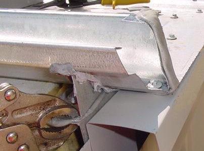
73 RAKE ZEE GABLE 71 Photo 1 Rake Zee modified at End Dam Photo 2 Rake Zee modified at Eave Trim Photo 3 Rake Zee modified at Eave Trim. Photo 4 Rake Zee modified at Gutter
74 GABLE TRIM INSTALLATION 72 GABLE TRIM (556357) GABLE LOCK (556358) GABLE TRIM GENERAL: The Gable Trim (556357) finishes the building gable, protecting the roof-to-wall joint. The Gable Trim is fastened to the Rake Zee and secured against the wall panel in the sliding lip of the Gable Lock (556358). This provides a watertight joint that will accommodate roof movement. If the Gable Trim is not kept straight, the building will have a poor appearance from the ground. A straight edge across the top of the Rake Zee and a panel seam can give a good reference for the top of the Gable Trim.
75 GABLE TRIM INSTALLATION 73 GABLE TRIM INSTALLATION 1) Starting at the low eave, apply 1/8 x 1/2 (3 x 13) sealer ( ) to the top of the Rake Zee. 2) Position the low end of the Gable Trim within 3 (76) of the end of the Rake Zee. The Gable Corner Box will have to lap by at least 2 (51). 3) Check that the Gable Trim is straight and true and clamp to the Rake Zee. Fasten to the Rake Zee using 1/4-14 x 3/4 stitch 12 (305) o/c 4) Continue installation up the gable until the Gable Trim is even with the high end of the SSR Panel. Splice the Gable Trims by lapping 2 (51) using 1/8 x 1/2 (3 x 13) sealer and 4) 1/4-14 x 3/4 stitch screws. 5) Apply a row of outside wall panel closures where the Gable Lock leg will fall. The bottom of the closure should be 9 (229) from the top of the SSR Panel. 6) Starting at the outside of the wall corner trim, hook the Gable Lock (556358) on the bottom of the Gable Trim. Fasten the Gable Lock through the wall panel closures to the panel high ribs using 1/4-14 x 3/4 stitch 12 (305) o/c. Do not screw the Gable Lock to the Gable Trim. The Gable Trim must slide with the SSR Panel s movement. 7) On a monoslope building, continue the Gable Lock to the far side of the building, ending at the outside of the corner trim. 1) For a building with a ridge, stop the Gable Lock 12 (305) from the ridge. For roof slopes up to 2:12 (16.67:100), the Center Gable Cover (554185) will finish the Gable Trim at the ridge. For roof slopes steeper than 2:12 (16.67:100), a field fabricated Center Gable Cover will be used (see CENTER GABLE COVER INSTALLATION, page 77).
76 HIGH EAVE TRIM INSTALLATION 74 HIGH EAVE TRIM (556349) PURPOSE The High Eave Trim (556349) finishes the building high eave, protecting the roof-to-wall joint. The High Eave Trim is fastened to the End Dams and the wall panel. The High Eave Trim flexes as the SSR Panels expand and contract. The profile of the High Eave Trim matches the Gable Trim. As with the Eave and Gable Trims, the High Eave Trim must be kept straight to achieve quality results. Keeping the High Eave Trim straight can conceal minor imperfections in the line of the eave. HIGH EAVE TRIM INSTALLATION 1) Fill the joints between the End Dams with small balls of 1/8 x 1/2 (3 x 13) sealer ( ). 2) Apply a continuous line of 1/8 x 1/2 (3 x 13) sealer ( ) to the top of the End Dams. 3) Apply a row of outside wall panel closures where the High Eave Trim leg will fall. The bottom of the closure should be 9 (229) from the top of the SSR Panel. 4) Starting at the outside of the wall panel corner trim, place the High Eave Trim in position: A) Hold the bottom leg of the trim against the wall panel and closures. B) Rotate the trim so the top leg matches the roof slope, and set into the sealer. Check that the High Eave Trim profile is in line with that of the Gable Trim. C) Clamp in position and check for straightness. Adjust if necessary. 5) Fasten the High Eave Trim to each End Dam using 4) 1/4-14 x 3/4 stitch screws and to the wall panel using 1/4-14 x 3/4 stitch screws 12 (305) o/c. 6) Splice the High Eave Trims using 1/8 x 1/2 (3 x 13) sealer ( ) and 4) 1/4-14 x 3/4 stitch screws.
77 GABLE CORNER BOX INSTALLATION 75 GABLE CORNER BOX (556427) GABLE CORNER BOX GENERAL The Gable Corner Box (556427) caps the gable-to-eave joint at the high and low eaves. The Gable Corner Box is sized to fit the Gutter and needs to be notched to fit an Eave Trim. Orient the Corner Box with the 7 1/2 (191) leg along the eave to match the top of the Gable Cover. A) GUTTER:
78 GABLE CORNER BOX INSTALLATION 76 B) EAVE TRIM: NOTE: The SSR Panel rib under the Gable Corner Box may have to be beveled to match the eave trim.
79 CENTER GABLE COVER INSTALLATION 77 CENTER GABLE COVER (554185)-FOR SLOPES UP TO 2:12 (16.67:100) (FIELD FAB)-FOR STEEPER SLOPES CENTER GABLE COVER GENERAL The Center Gable Cover ( or Field Fabricated) joins the Gable Covers at the ridge, flexing to accommodate the expansion and contraction of the roof surfaces. The Gable Covers should end even with the roof panels, leaving an 8 (203) gap ( ). A) STANDARD CENTER GABLE COVER (554185): -Roof slopes up to 2:12 (16.67:100) SEE DRAWING NEXT 1) Apply outside wall panel closures. 2) Fasten the Center Gable Cover to the Gable covers using 1/8 x 1/2 (3 x 13) sealer ( ) and 1/8 (3) pop rivets supplied. 3) Fasten the bottom leg of the Center Gable Cover to the wall panel using 2) 1/4-14 x 3/4 Stitch Screws. The screws must not interfere with the Gable Cover movement. 4) Lap the Ridge Cap (554426) onto the Center Gable Cover by 3 1/2 (89). Seal to the End Dams and Center Gable Cover using 1/8 x 1/2 (3 x 13) sealer ( ). Fasten using 1/4-14 x 3/4 stitch screws. Ensure that at least one screw per side penetrates all trims and the Rake Zee. 5) Apply 3/8 (10) bead of Sika Tube Caulk (995051) to the underside of the End Cell (556391) and fasten to the Ridge Cap and Gable using 10) 1/4-14 x 3/4 Stitch Screws. The End Cell must cover the split top of the Center Gable Cover.

80 CENTER GABLE COVER INSTALLATION 78
81 CENTER GABLE COVER INSTALLATION 79 B) FIELD FABRICATED CENTER GABLE COVER Required for roof slopes steeper than 2:12 (16.67:100) 1) Fabricate a Center Gable Cover as shown: 2) Install the Center Gable Cover as you would a standard Center Gable Cover (see part A)
82 SLIDING STEP DETAIL (TRANSITION WALL OR PARAPET) 80 STEP DETAIL HIGH WALL NOTE: It is preferable to start panel installation at the high wall steel line. Indicate when ordering if down slope seaming will be required to start panel installation at the high wall. See PREPARATION: START POINT AND DIRECTION OF INSTALLATION, page 24, for complete explanation of panel notching and seaming direction. SLIDING STEP DETAIL It is common for the roof to join to a higher building or parapet at the endwall. The joint must be able to slide as the roof expands and contracts yet remain watertight. Standard parts are used for the connection; however, some fieldwork is required when an eave or ridge is involved. The wall panels for the high wall above the roof cannot be installed until the SSR Step detail is completed. The high wall panels adjacent to the roof may be installed ahead of roof panel installation. NOTE: If the SSR Panel against the high wall is not full width, the seam may have to be closed before the flashings are installed. Check that the seamer will have enough clearance before installing flashings. GENERAL INSTALLATION NOTE: Installation of the step detail is similar to the Gable. Refer to the appropriate Eave and Ridge details in the Standard Detail Booklet to be used in conjunction with the General Installation procedure. 1) Transition Wall: Install a row of Base Angle (556019) with the 2 (50) leg up at the high wall steel line. Parapet Wall: Install a row of Parapet Base Angle, with long leg up, at parapet inside steel line. 2) Fasten base angle to the purlins using 2) #12-14 x 1 SD Tek screws per purlin. Keep the screws at least 1 1/4 (32) from the steel line to avoid interference with the SSR Clips. 3) Transition Wall: Install a row of SSR Clips at the high wall steel line (see FIRST ROW OF SSR CLIPS, page 36). When installing 1 ¾ (44) SSR Clips at transition wall, bend the clip shoulders up to clear the Base Angle. Parapet: Install a row of SSR Clips 1 (25) from parapet inside steel line.
83 SLIDING STEP DETAIL (TRANSITION WALL OR PARAPET) 81 4) Install a row of Eave Plates (same Pt.# as used at the 4 (100) from the steel line to support the SSR Panel. The Eave Plates will prevent the SSR Panel from pulling away from the Wall Panel Support (556019). 5) Install Thermal Blocks (by others) if used, and SSR Panels (see STARTER PANEL INSTALLATION, page 41 and PANEL TERMINATION, page 53). Fasten the SSR Panel to the sliding tabs of the SSR Clips using 2) 1/4-14 x 3/4 stitch screws per clip. NOTE: Check for seaming machine clearance. The first panel seam from the high wall may need to be closed before proceeding. 6) If the low roof has a ridge located on the high wall: Install the End Dam (556380) near the high end of the SSR Panel (see END DAM INSTALLATION page 67). If the low roof has a high eave located on the high wall: Install the End Dam after the Rake Zee 7) Install the Wall Panel Support (556091). Start at the low side and work upslope, lapping the upslope pieces onto the downslope pieces by 2 (50) using Gun Grade Mastic (995053) inside the laps. Tack the Panel Supports to the high wall girt, keeping the fasteners as high as possible on the back of the support. 8) Install the Rake Zee (556355) (see Rake Zee Gable ) starting at the high side and working downslope. Use 1/8 x 1/2 (3 x 13) sealer ( ) under the Rake Zee and Gun Grade Mastic ( ) inside the splices. Fasten to the SSR Panel using 1/4-14 x 7/8 Scots stitch screws. Do not screw into the roof framing or Eave Plate. 9) Install the Hip Flashing (556411). Start at the low side and work upslope, lapping the pieces 2 (50). Use 1/8 x 1/2 (3x13) sealer ( ) & 1/4-14 x 3/4 stitch screws to seal the laps. A) Apply a 1/4 (6) bead of Sika Tube Caulk (995051) to the back of each Hip Flashing to form a flexible seal to the Panel Support. Position the Hip Flashing carefully so the caulking remains intact. B) Fasten to the Rake Zee using 1/8 x 1/2 (3 x 13) sealer ( ) and 1/4-14 x 7/8 Scots stitch 12 (305) o/c. Do not fasten to the Panel Support; the Hip Flashing must slide with the roof. 10) Install the wall panels using inside closures c/w 1/8 x 1/2 (3 x 13) sealer ( ) both sides. Fasten through the wall panel support into the girt using 1/4-14 x 1 1/2 or 2 SD Tek 6 (152) o/c. Wall panel screws must not penetrate the Hip Flashing. Seal the wall panel sidelaps using 1/8 x 1/2 (3 x 13) sealer ( ) and 1/4-14 x 3/4 stitch 6 (150) o/c to 5-0 (1524) above the roof.
84 SLIDING STEP DETAIL (TRANSITION WALL OR PARAPET) 82 SEAL SEAMS TO 60" (1524) ABOVE BASE OF WALL PANEL USING 1/8" x 1/2" (3 x 13) SEALER ( ) AND 1/4-14 x 3/4" STITCH 6" (150) O/C. SIKA TUBE CAULK (995051) BEHIND PANEL SUPPORT LEG. HIP FLASHING (556411) (WALL PANEL SCREWS MUST NOT PENETRATE LEG OF FLASHING) SIKA TUBE CAULK (995051) IN PANEL SEAM. SEE "ICE DAMMING PROTECTION". THERMAL BLOCK (IF APPLICABLE) BY OTHERS 1/4-14 x 7/8" SCOTS STITCH 12" (300) O/C TOP & BOT C/W 1/8" x 1/2" (3 x 13) SEALER ( ). RAKE "Z" (556355), LAP ENDS 4" (100) USING GUN GRADE MASTIC (995053) INSIDE SPLICE TO ENSURE WATER-TIGHT SEAL. EAVE PLATE (EXCEPT WITH 1 3/4" (44) CLIPS) UNDER TO SUPPORT PANEL. SAME PT# AS AT LOW EAVE. WALL CLADDING RESTING ON HIP FLASHING 8" (203) TRANSITION WALL INSIDE CLOSURE WITH 1/8" x 1/2" (3 x 13) SEALER ( ) BOTH SIDES. #12-14 x 1 1/2" OR #12-14 x 2" WALL PANEL TEK 6" (150) O/C. SSR CLIP AT STEEL LINE. (FOR OPPOSING DETAIL, INSTALL CLIP "REVERSED"). FASTEN PANEL TO SLIDING TAB USING 2) 1/4-14 x 3/4" STITCH. NOTE: BEND SHOULDERS OF 1 3/4" (44) CLIP TO CLEAR BASE ANGLE. FIELD CUT AND BEND PANEL UP AS SHOWN IF RIB DOES NOT FALL ON STEEL LINE. PANEL SUPPORT (556091) (FASTEN AT GIRT 6" (150) C-C.) BASE ANGLE (556019) C/W (2) #12-14 x 1" SD TEK SCREWS PER PURLIN. #12-14 x 1" SD TEK 24" (600) O/C PARAPET PANEL RESTING ON HIP FLASHING SSR CLIP 1" FROM STEEL LINE (FOR OPPOSING DETAIL, INSTALL CLIP REVERSED) 9 1/2" (241) PARAPET BASE ANGLE C/W (2) #12-14 x 1" SD TEK SCREWS PER PURLIN. 1" (25) DEPTH OF PARAPET PARAPET SAME AS TRANSITION WALL EXCEPT AS NOTED
85 RIDGE CAP INSTALLATION 83 RIDGE CAP (554426) PURPOSE The Ridge Cap (554426) is designed to flash off the joint between the two roof surfaces while flexing to accommodate the SSR Panel movement. Once the SSR Panels, End Dams, & Gable Cover have been installed, Ridge Cap Installation can proceed. It is preferable for installation to proceed into the prevailing wind so that the Ridge Cap laps will be better protected. RIDGE CAP INSTALLATION 1) Place a small ball of 1/8 x 1/2 (3 x 13) sealer ( ) over each End Dam joint to seal any gaps present. Apply 1/8 x 1/2 (3 x 13) sealer ( ) along the top of the End Dams & 3 1/2 (89) onto the Center Gable Cover. 2) Start the Ridge Cap lapped 3 1/2 (89) onto the Center Gable Cover and centered on the ridge. 3) Fasten using 4) 1/4-14 x 7/8 Scots stitch screws per End Dam. 4) Lap the Ridge Caps 2 (51) using 1/8 x 1/2 (3 x 13) sealer ( ) inside the lap and 8) 1/4-14 x 3/4 stitch screw
86 RIDGE CAP EXPANSION DETAIL 84 TOP RIDGE CAP OVERLAPS 2" (50) SIKA TUBE CAULK (995051) 2) 1/4" (6) BEADS ACROSS TOP 1) 1/4 (6) BEAD EACH SIDE. FASTEN TOP RIDGE CAP TO BACKING 3" (76) O/C. SIKA TUBE CAULK (995051) AT SIDES AND ACROSS TOP OF BACKING STRIP 1" (50) 1" (50) KEEP SCREWS BACK 2 1/2" (64) FROM ENDS OF RIDGE CAPS TO PERMIT MOVEMENT 6" (150) BACKING STRIP CUT FROM RIDGE CAP (554426) END DAM (556380) FIRST RIDGE CAP IN DETAIL 1/8" x 1/2" (3 x 13) SEALER ( ) PANEL RIDGE CAP EXPANSION DETAIL The Ridge Cap on long buildings can be susceptible to leaks caused by thermal expansion and contraction. On buildings longer than 250 (76 200), the Ridge Cap Expansion Detail is installed every 200 (60 960) to minimize damage to the Ridge Cap joints. Any roofs less than 250 (76 200) long will not require an Expansion Detail. INSTALLATION 1) Locate the Expansion Details to break the Ridge Cap into approximately 200 (60 960) sections. The Expansion Detail will be located over a Panel seam/ End Dam joint. 2) When Ridge Cap installation reaches the Panel seam where the Expansion Detail will be located, cut or position the Ridge Cap to run 1 (25) past the Panel seam. 3) Place 1/8 X 1/2 (3 X 13) Sealer ( ) on the top leg of the End Dams (see END DAM INSTALLATION, page 67). 4) Cut a 6 (150) piece of Ridge Cap for use as a Backing Strip. Position it as shown so that the first Ridge Cap in the Detail will overlap by 2 (50). 5) Caulk the sides and across the top of the Backing Strip using 1/4 (6) beads of Sika Tube Caulk (995051). Be sure that the caulking extends to the End Dam sealer. 6) Position the first Ridge Cap in the Detail, and fasten to the End Dams. Do not install any screws closer than 2 1/2 (64) to the end of the Ridge Cap. The Backing Strip must not be attached to the first Ridge Cap. 7) Place 2) 1/4 (6) beads of Sika Tube Caulk (995051) across the Ridge Cap at 1 (25) and 1 1/2 (38) from the end of the Ridge Cap. Caulk the sides of the Ridge Cap. 8) Overlap the next Ridge Cap and fasten to the End Dams. Screw this Ridge Cap to the Backing Strip using 1/4-14 x 1 1/8 Endlap Screws 3 (76) o/c. Install the screws 2 1/2-3 (64 75) from the end of the Ridge Cap to avoid restricting the movement of the Ridge Cap beneath. Ensure that the top Ridge Cap and the Backing Strip are clamping the first Ridge Cap securely without flaring.
87 LEAN-TO HIGH EAVE DETAIL 85 LEAN-TO HIGH EAVE DETAIL LEAN-TO HIGH EAVE DETAIL HIGH WALL PANEL RESTING ON HIP FLASHING SEAL SEAMS TO 60" (1524) ABOVE BASE OF WALL PANEL USING 1/8" x 1/2" (3 x 13) SEALER ( ) AND 1/4-14 x 3/4" STITCH 6" (150) O/C. (4) 1/4-14 x 7/8" SCOTS STITCH SCREWS PER END DAM C/W 1/8" x 1/2" (3 x 13) SEALER ( ). #12-14 x 1 1/2" OR #12-14 x 2" WALL PANEL TEK 6" (150) O/C. END DAM (556380) APPLY GUN GRADE MASTIC (995053) ALONG END DAM TO PANEL SEAM (FEATHER EDGES) 4"± (102)± INSIDE CLOSURE WITH 1/8" x 1/2" (3 x 13) SEALER ( ) BOTH SIDES 8 1/2" (216) SIKA TUBE CAULK (995051) 6" (150) SIKA TUBE CAULK (995051) IN PANEL SEAM TO 10'-0" (3048) INSIDE MALE RIB TO SEAL SEAM FROM HIGH WALL. SEE AT END DAM. "ICE DAMMING PROTECTION". ENDLAP PLATE (556076). PANEL SSR CLIP THERMAL BLOCK (IF APPLICABLE) BY OTHERS (6) 1/4-14 x 1 1/8" (556376) PER END DAM INTO ENDLAP PLATE. PURLIN 9" (229) 12" (305) 3" (76) HIP FLASHING (556405) 3/32" x 1 1/2" (2 x 38) MASTIC PAD ( ). USE GUN GRADE MASTIC (995053) TO SEAL SMALL GAPS AS REQUIRED
88 LEAN-TO HIGH EAVE DETAIL 86 GENERAL The Lean-To High Eave Detail provides a flexible connection from the high wall to the SSR roof. Extra sealer is applied in the seams of both the roof and high wall panels to protect against ice damming. See ICE DAMMING PROTECTION page 49. The high wall panels above the roof panels cannot be installed until the high eave detail has been completed. The high wall panels adjacent to the low roof may be installed ahead of time. It is preferable for Hip Flashing installation to proceed into the prevailing wind so that the Hip Flashing laps will be better protected. LEAN-TO HIGH EAVE INSTALLATION NOTE: Refer to the appropriate lean-to Gable details in the standard detail booklet to be used in conjunction with the General Installation. 1) Install the SSR Panels, End Lap Plates, End Dams, Rake Zee, and Gable Trims as required. 2) Place a small ball of 1/8 x 1/2 (3 x 13) sealer ( ) over each End Dam joint to seal any gaps present. Apply 1/8 x 1/2 (3 x 13) sealer ( ) along the top of the End Dams and onto the Gable Trims. 3) Fasten the Hip Flashing (556405) to the top of the End Dams using 4) 1/4-14 x 7/8 Scots stitch screws per End Dam. Tack the back of the Hip Flashing to the High Building girt using #12-14 x 1 1/2 or 2 SD Tek screws. Keep the screws as high on the trim as possible. NOTE: Ensure that the Hip Flashing is installed straight and is sloped to drain onto the low roof. 4) Lap the Hip Flashings 2 (50) using 1/8 x 1/2 (3x 13) sealer ( ) inside the lap and 1/4-14 x 3/4 stitch screws. 7) Install the high wall panels using inside closures c/w 1/8 x 1/2 (3 x 13) sealer ( ) both sides. Fasten through the wall panel closures into the girt using #12-14 x 1 1/2 or 2 SD Tek 6 (152) o/c. Seal the high wall panel sidelaps using 1/8 x 1/2 (3 x 13) sealer ( ) and 1/4-14 x 3/4 stitch 6 (150) o/c to 5-0 (1524) above the roof.
89 ROOF PENETRATIONS 87 ROOF CURB PIPE FLASHING ROOF PENETRATIONS Roof penetrations must be flashed in such a way that the movement of the roof will not be interfered with and leaks will not occur. Generally, there are two methods for flashing roof penetrations: Pipe Flashing and Roof Curbs. Smaller pipes (up to 16 (406) in diameter) can be flashed using dektites. Larger openings will require the use of a roof curb. PIPE FLASHING INSTALLATION Dektites may be ordered to seal any pipes projecting through the roof panels. The base of the Dektite will conform to the slope of the roof and/or the panel rib. 1) Locate the penetrating pipe so that the panel rib will not have to be cut. Plumbing vent pipes can be elbowed to hit the flat of the panel. 2) Cut a hole in the panel leaving 1 (25) clear all around the pipe to allow room for roof movement. 3) Cut the top of the Dektite at the appropriate mark to provide a tight fit for the pipe. Leave 1/2 (12) straight collar against pipe for maximum sealing. 4) Slip the Dektite over the pipe and bend the base to conform to the panel rib, if necessary. Water may be used to lubricate the pipe when sliding the Dektite on. 5) Apply Gun Grade Mastic (995053) between the base of the Dektite and the panel, and at the top of the Dektite. 6) Use 1/4-14 x 1 1/8 (556376) endlap screws to fasten the Dektite to the panel.
90 ROOF PENETRATIONS 88 ROOF CURBS There are various types of Roof Curbs available to accommodate HVAC and other roof-mounted equipment. These curbs can be installed in one of three ways: 1) Retrofit curbs are available that simply sit on top of the roof panels, set in sealant and fastened all the way around. 2) Screw-down curbs are available that will slide under the upslope panel and over the downslope panel, also set in sealant and fastened all the way around. 3) Seamed in place curbs are available that lap with the panels up-and-downslope of the opening and are seamed into the adjacent panels. Standing seam roof curbs must have two main components. The inside of the curb supports the weight of the equipment, resting on the building structure. The outside of the curb is flashed to the roof panels and must be able to move with the rest of the roof. All curbs must have water diverters or crickets on the high side to prevent water from ponding, and must have sufficient clearance at the sides to allow proper drainage.
91 INDEX 89 INDEX Base Angle (556019) Center Gable Cover ( or Field Fabricated) Checking Roof Geometry Component Selection Chart Downslope Seaming Eave Plate Eave Trim (556419) End Caps ( & )... 66, 70 End Cell (556391) End Dam (556380) Endlap Plate (556076) Endlaps... See Panel Endlaps First Row of SSR Clips Gable Corner Box (556427) Gable Lock (556358) Gable Trim (556357) Gutter Hanger Strap (556031) Gutter Trim ( female & male) High Eave Trim (556349) Hip Flashing (556405) Hip Flashing (556411) Ice Damming Protection Installation For Long-Term Performance... 1 Lean-To High Eave Detail Metal Eave Closure (556369) Notching... See Start Point, See Panel Endlaps On-Site Handling Panel Endlaps Panel Layout Eave Endlaps Panel Overhang Tolerance Ridge / High Eave Panel Properties... 6, 7 Panel Seaming Panel Seaming Procedure Starting Platform Panel Termination Field Modified Full Width Primary Eave Trim (556428) Rake Angle (556020) Rake Zee (556355) End Caps ( & ) Ridge Cap (554426) Ridge Cap Expansion Detail Roof Penetrations Dektites Roof Curbs Safety... 5 Seamer Specifications... 58, 59 Adjustment Sliding Step Detail Standard Panel Installation Standing Seam Roof Parts Sealants... 8 Sealer Calculation... 9 Start Point and Direction of Installation Acceptable Start and End Locations Endlap Notching Starter Panel Field Modified Full Width Table of Contents... 2 Wall Panel Support (556091)... 81
92 NOTES 90 ERECTOR NOTES The most valuable member of our research and development team is the erector in the field. The performance of our product in the field is crucial, and any feedback is greatly appreciated. These pages have been provided for your use.
93 NOTES 91
94


95 Due to continuing research and development, Behlen Industries reserves the right to modify any of the details and procedures covered in this Manual without notice.