DE-SPAN Design Guideline. Manufactured 100% indoors. Under 100% controlled conditions.
|
|
|
- Basil Hawkins
- 5 years ago
- Views:
Transcription


1 DE-SPAN Design Guideline Manufactured 100% indoors. Under 100% controlled conditions.


 of natural stream End and inside modules can be skewed")

2 DE-SPAN DE-SPAN is a rigid-portal framed bridge system. Modules are designed with a horizontal deck to support soil & live loads and vertical legs to create desired opening height. Open bottomed bridge Preserves natural stream bed and path Existing soils and vegetation preserved Sustans fish and wildlife habitat Modules designed to suit meander geometry (planform) of natural stream End and inside modules can be skewed Laying length can vary No maximum on bridge length Buried bridge structure Limits exposure of structural elements to environment Reduces maintenance and life cycle costs Architectural finishes can be added 2 DE-SPAN de-span@decastltd.com


3 DE-SPAN at a Glance Manufactured precast modules for set-in-place construction of a bridge. Precast frame modules, wingwalls, headwalls, endwalls and footings. Spans range from a minimum of 4 m to a maximum of 16 m High quality, test-fitted modules Can be inspected by a contract administrator at our manufacturing facility prior to shipment Bridge legs sit in precast keyway footings Can be manufactured well in advance and installed within environmental windows for preservation of fish and wildlife habitat Varying skews available Fast installation to minimize traffic interruptions Span: Width of the frame from inside the leg on one side to inside the leg on the other side. Rise: Distance from the bottom of the vertical leg to the underside of the deck at midpoint. Laying Length: Individual length of modular section. Can vary from 1.2m to 2.5m. Leg Thickness: 250 mm minimum. Deck Thickness: 250 mm minimum. de-span@decastltd.com DE-SPAN 3
4 Design of DE-SPAN Design of DE-SPAN for projects is completed by experienced structural engineers at DECAST Ltd. Project engineers may wish to do a structural efficiency analysis or preliminary design for site conditions. Final structural design will be done by DECAST Ltd. engineers based on information provided. T/ROAD DE-SPAN PRECAST CONCRETE BRIDGE - DE-SPAN BRIDGE SYSTEM (DESIGN BY DECAST LTD.) LIMIT OF EXCAVATION EARTH COVER KEYWAY RISE SPAN WL (VARIES) WALL DRAIN REINFORCED CONCRETE FOOTING (PRECAST OR CAST-IN-PLACE) NATURAL STREAMBED TYPICAL DE-SPAN SECTION Waterway Areas (M 2 ) for Span / Rise Combinations Span (mm) Rise (mm) A pedestal footing can be used to accommodate rises greater than 2.4m 4 DE-SPAN de-span@decastltd.com
5 How to Specify DE-SPAN 1 Span is determined by site conditions. If the bridge is crossing a stream bed, span is determined by the width of the stream bed and rise is determined by the necessary waterway area calculated in hydraulic analysis. 2 Specify the top of road grade, earth cover and live loads. Minimum cover for all spans is 0.3 m. Maximim earth cover is detailed in the table below. If not otherwise stated, DE-SPAN will be designed in accordance with the Canadian Highway Bridge Design Code (CHBDC). Maximum Earth Cover (m) Span (m) Allowable cover values may vary. 3 Specify footings required and provide a geotechnical report if DECAST engineers are to design precast footings. Precast footings are recommended to minimize stream bed disruption and speed construction. 4 Show the path DE-SPAN must follow. Show the centre line of the road and the centre line of DE-SPAN (for a stream crossing). Show any roadway skews or module section skews required. Show any roadway and stream bank slopes. Show any headwalls, endwalls and wingwalls required. Show any cast-in requirements for guardrails, approach slabs, railings etc. or any holes for adjoining storm pipe or culvert connections. ROADWAY SKEW DE-SPAN LENGTH ROAD WIDTH TYPICAL DE-SPAN SITE LAYOUT de-span@decastltd.com DE-SPAN 5
6 Typical Methods to Handle Road Skews Use a Longer Lay Length In order to ensure that culverts or precast bridges span a road and accommodate the road skew, the lay length is often increased. Using this method to handle road skews causes the concrete structure to protrude from the road embankment. ROADWAY SKEW It is then exposed to the elements and the protruding piece is a potential hazard to motorists. LENGTH DE-SPAN Skew End Pieces Only In this method the lay length is shorter than the previous method. The road skew is handled by skewing the end pieces only but this limits the skew angle that can be accommodated. The skew limit decreases as the bridge span increases. SKEWED END PIECE MAX ~ 4m ROADWAY SKEW DE-SPAN MIN ~ 1m LENGTH 6 DE-SPAN de-span@decastltd.com
7 The DE-SPAN Advantage DE-SPAN can be designed and manufactured to minimize the lay length while accommodating any skew angle. There are no DE-SPAN sections with a long and short lay length. This is an ideal way to accommodate right of ways and site limitations while ensuring there are no protruding concrete sections. SKEWED PIECE ROADWAY SKEW DE-SPAN LENGTH DE-SPAN Section Dimensions Span (mm) Dimensions (mm) Deck Thickness Leg Thickness Haunch Length Haunch Height Laying Length de-span@decastltd.com DE-SPAN 7


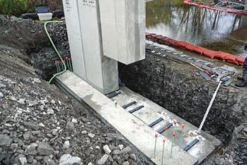
8 Installation DE-SPAN bridges can typically be installed in one or two days. Precast footings can be installed one day and the next day DE-SPAN sections can be installed by fitting the bridge legs into the keyway footings. Precast Footings It is recommended that designers specify precast footings to minimize stream disruption, minimize excavation and to speed construction. Making accurate footings that fit the bridge legs ensures the bridge will perform well structurally. Cast-In-Place footings for a bridge are the most disruptive part of construction in a natural stream and construction crews on site have limited time when faced with environmental regulations. Precast footings are designed, manufactured and fitted to precast bridge legs in our manufacturing facility before they are shipped. Layout Diagram The installation contractor and the contract administrator are provided with a layout diagram showing the suggested installation procedure and section layout. All modular sections are numbered and the numbered sections are shown on the diagram. CONSTRUCTION NORTH 2500 R R R1 R5 A1 A2 A3 A4 A5 A6 A7 A8 A9 A = 20, R7 600mm FILTER FABRIC OVER JOINT TYP. R R TYPICAL DE-SPAN LAYOUT 4110 R DE-SPAN de-span@decastltd.com

9 Installation DECAST Ltd. supplies all materials for site installation including any joint materials and lift connection devices. All DE-SPAN sections are designed and manufactured with swift lift connection devices to ensure safe and efficient lifting. A DECAST Ltd. field services representative is available to provide technical assistance during installation. DE-SPAN Section Masses Span (mm) Mass (kg) per section Rise (mm) ,842 14,818 15,793 16,768 18,716 20,666 22, ,013 15,989 16,964 17,939 19,887 21,837 23, ,695 18,136 19,308 20,479 22,817 25,159 27, ,756 18,781 19,807 20,832 22,879 24,929 26, ,781 19,807 20,832 21,857 23,904 25,954 28, ,021 20,132 21,242 22,353 24,571 26,972 29, ,440 19,446 20,491 21,517 23,564 25,615 27, ,742 20,682 21,621 22,561 24,437 26,317 28, ,231 22,303 23,375 24,446 26,586 28,730 30, ,160 21,135 22,109 23,084 25,030 26,979 28, ,523 22,620 23,717 24,814 27,004 29,198 31, ,547 23,534 24,521 25,508 27,478 29,452 31, ,322 29,419 30,516 31,613 33,803 35,997 38, ,502 27,575 28,648 29,751 31,864 34,011 36, ,289 27,306 28,310 29,341 31, ,882 30,899 31,903 32,933 34, ,270 32,287 33,291 34,322 36, ,685 36,795 37,891 39,016 41, ,194 37,304 38,400 39,524 41, Note: This table is provided as a general guideline for lifting equipment. Actual section masses will vary. They will be marked on the manufactured section de-span@decastltd.com DE-SPAN 9

10 Quotations for DE-SPAN DECAST Ltd. engineering department will determine the total lay length of the DE-SPAN from the project layout drawing and the number and size of modular pieces taking into account site conditions and weights for transportation and lifting. DECAST Ltd. estimators will provide a quotation outlining the number, size weight and type of modular sections necessary to completely assemble the DE-SPAN for the project. This will include portal frame sections (with or without skews), wingwalls, headwalls, endwalls and footings. Design by DECAST Ltd. Structural Engineers When the DE-SPAN order is finalized, DECAST Ltd. engineers will complete the structural design of the DE-SPAN bridge and create shop drawings. Shop drawings will be submitted to the contractor and project engineer for review and approval. DECAST Ltd. will then provide final stamped (sealed) drawings. These shop drawings will be used to manufacture the DE-SPAN modules and for inspection by the contract administrating engineer. A *B* B REINFORCEMENT (PER UNIT) TOP AS5 TOP AS1+ AS5 OUTSIDE AS1+ AS Ø150 AS2 SECTION A-A AS2 SECTION B-B AS3 SECTION C-C Ø100 *A* * DIMENSION IS OUTER TO OUTER PLAN VIEW 3 - AS8 3 - AS8 AS5 AS1 B A B RISE A AS2 AS8 AS6 AS C L Ø75 PVC PIPE (BOTH LEGS) C C AS3 AS AS FRONT VIEW 457 SIDE VIEW 10 DE-SPAN de-span@decastltd.com

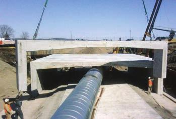
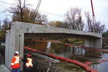
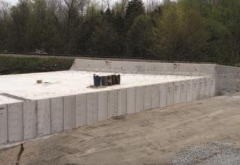
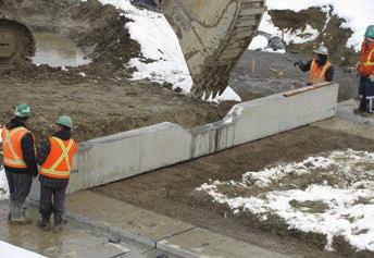

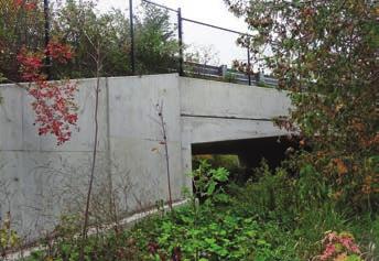
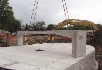
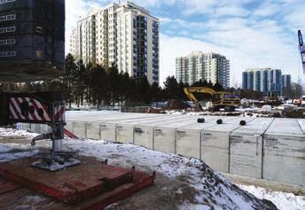
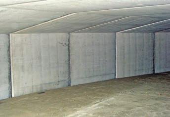
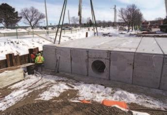

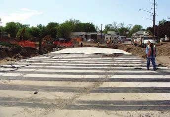
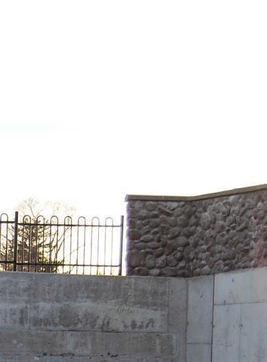
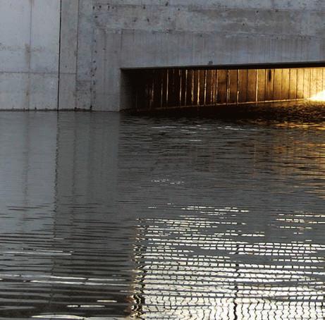
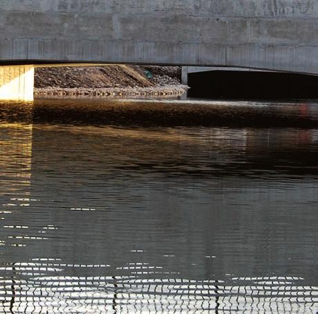
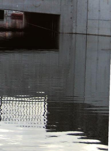
11 DE-SPAN On Site DE-SPAN 11
12 CONTACT INFORMATION SALES CONTACTS Rob Micieli Sales Manager Mauro DeFranco, P. Eng Sales Engineer Frank Mazza John Pozzobon C.E.T. Martin Fischer Sales: Engineering: The most extensive product line portfolio in the industry Prestressed concrete cylinder pipe and fittings Valve and utility chambers Steel pipe and fittings Bridge girders DE-SPAN Bridge superstructure and substructure General Information and Enquiries: LOCATION The DECAST Ltd. manufacturing facility and head office are located just over an hour s drive north of Toronto, and 10 minutes west of Barrie. DECAST Ltd. is located in Essa Township. DECAST Ltd County Road 56 Utopia, ON L0M 1T Engineering Fax: Shipping Fax: Tunnel segments Box culverts Reinforced concrete pipe Maintenance holes and catch basins Headwalls Railway/Subway ties Manufactured 100% indoors. Under 100% controlled conditions. DECAST Ltd All rights reserved. All images are protected by Copyright laws. If you would like to use any images from this brochure, from our website, or in print, you must receive prior written consent from DECAST Ltd. The descriptions, designs, data and information contained herein are believed to be accurate and are provided for guidance only. No warranties of any kind, either expressed or implied, are made regarding the products, design, and information described in this brochure.