Safety margins for this property are as follows: Prior to Instalation: PSI Saftey After Instalation: PSI Safety
|
|
|
- Brice Tyler
- 5 years ago
- Views:
Transcription
1

2 RD AVENUE, SUITE D AURORA, CO PHONE: (303) STATE LICENSE # December 27, 2016 Westminster Fire Department 9110 Yates Street Westminster, Colorado Subject: New Backflow Preventor Requirement To whom it may concern: Due to the new backflow preventor intallion requirement in each pit, AAA Fire Protection, Inc. has went back and assessed the hydraulic calculations to ensure that they maintained an adequate safety margin. In reference to N. Yates Dr., after installation of a 1 inch Double Check Backflow Preventor this property will still have an adequate safety margin per NFPA 13D. Safety margins for this property are as follows: Prior to Instalation: PSI Saftey After Instalation: PSI Safety Sincerely, Damon E. Huff President AAA Fire Protection, Inc. AAA Fire Protection Inc. takes great pride in its workmanship therefore if you re not happy we're not happy INSPECTION / DESIGN / INSTALLATION / BACKFLOW TESTING

3 AAA FIRE PROTECTION, INC East 33 rd Avenue, Unit D Aurora, CO PRODUCT DATA SHEETS December 27, 2016 Ryland Homes 6161 S. Syracuse Way Ste. #200 Greenwood Village, CO Legacy Ridge Patio Villas- Plan N. Yates Dr. Westminster, CO Passive Purge System


4
5 10995 N. Yates Dr., Westminster, CO Pg. 1 Pg. 2 Pg. 3 Title Page/Project Sheet Owner's Responsibility for Fire System Index Section 1 Calculation 1 Section 2 Calculation 2 Section 3 Calculation 3 Section 4 Section 5 Section 6 Section 7 Section 8 Section 9 Section 10 Section 11 Heads Pipe/Fittings Bronze Check Valve Bronze Ball Valve Meter Pit Detail Diagram Backflow Preventer Exposed CPVC Unfinished Basements Spears & Hilti Insulation Compatibility

6
7 SPRINKLER SYSTEM HYDRAULIC ANALYSIS Page 2 DATE: 8/13/2015 C:\HASS78\CALCS\LEGACY RIDGE\3212\CALC1.SDF JOB TITLE: LEGACY RIDGE-PLAN 3212-CALC 1 WATER SUPPLY DATA SOURCE STATIC RESID. FLOW AVAIL. TOTAL REQ'D NODE PRESS. DEMAND PRESS. TAG (PSI) (PSI) (GPM) (PSI) (GPM) (PSI) SRC AGGREGATE FLOW ANALYSIS: TOTAL FLOW AT SOURCE 32.4 GPM TOTAL HOSE STREAM ALLOWANCE AT SOURCE 0.0 GPM OTHER HOSE STREAM ALLOWANCES 0.0 GPM TOTAL DISCHARGE FROM ACTIVE SPRINKLERS 32.4 GPM NODE ANALYSIS DATA NODE TAG ELEVATION NODE TYPE PRESSURE DISCHARGE (FT) (PSI) (GPM) K= K= A B B B B TOR BOR MT MT SRC -3.0 SOURCE
8 SPRINKLER SYSTEM HYDRAULIC ANALYSIS Page 3 DATE: 8/13/2015 C:\HASS78\CALCS\LEGACY RIDGE\3212\CALC1.SDF JOB TITLE: LEGACY RIDGE-PLAN 3212-CALC 1 PIPE DATA PIPE TAG Q(GPM) DIA(IN) LENGTH PRESS. END ELEV. NOZ. PT DISC. VEL(FPS) HW(C) (FT) SUM. NODES (FT) (K) (PSI) (GPM) FL/FT (PSI) Pipe: PL 3.00 PF FTG E PE 0.0 A TL PV Pipe: PL 1.00 PF FTG T PE 0.0 A TL 4.00 PV Pipe: PL PF 9.2 A FTG E PE 4.8 B TL PV Pipe: PL 8.00 PF 0.0 B FTG ---- PE 0.0 B TL 8.00 PV Pipe: 10A PL 9.00 PF 0.0 B FTG ---- PE 0.0 B TL 9.00 PV Pipe: PL PF 5.5 B FTG ET PE TL PV Pipe: PL 6.00 PF FTG E PE 0.0 B TL PV Pipe: PL PF 2.8 B FTG 2E PE 0.0 TOR TL PV Pipe: PL 7.00 PF 0.8 TOR FTG CG PE 3.0 BOR TL PV Pipe: 23A PL PF 24.0 BOR FTG E PE 0.9 MT TL PV Pipe: 23B FIXED PRESSURE LOSS DEVICE MT psi, 32.4 gpm MT Pipe: PL PF 13.9 MT FTG 4ETG PE 1.3 SRC -3.0 SRCE 91.7 (N/A) TL PV
9 SPRINKLER SYSTEM HYDRAULIC ANALYSIS Page 4 DATE: 8/13/2015 C:\HASS78\CALCS\LEGACY RIDGE\3212\CALC1.SDF JOB TITLE: LEGACY RIDGE-PLAN 3212-CALC 1 NOTES (HASS): (1) Calculations were performed by the HASS 7.9 computer program under license no granted by HRS Systems, Inc LaVista Road Tucker, GA (2) The system has been calculated to provide an average imbalance at each node of gpm and a maximum imbalance at any node of gpm. (3) Total pressure at each node is used in balancing the system. Maximum water velocity is 17.3 ft/sec at pipe 12. (4) PIPE FITTINGS TABLE Pipe Table Name: CUSTOM.PIP PAGE: K MATERIAL: CT-K HWC: 150 Diameter Equivalent Fitting Lengths in Feet (in) E T F R C S G N Ell Tee 45-Ell TeeRun Couplg SwgChk GatVlv NPTee PAGE: P MATERIAL: CPVC HWC: 150 Diameter Equivalent Fitting Lengths in Feet (in) E T L C R G B A D Ell Tee Lell SwgChk Rtee N
10 SPRINKLER SYSTEM HYDRAULIC ANALYSIS Page 5 DATE: 8/13/2015 C:\HASS78\CALCS\LEGACY RIDGE\3212\CALC1.SDF JOB TITLE: LEGACY RIDGE-PLAN 3212-CALC 1 G A U G E WATER SUPPLY ANALYSIS Static: psi Resid: psi Flow: gpm LEGEND FLOW (GPM) P R E S S U R E ( p s i ) 1 2 B A Available pressure gpm Required pressure gpm A. Source Supply Curve B. System Demand Curve 1 2
11 SPRINKLER SYSTEM HYDRAULIC ANALYSIS Page 6 DATE: 8/13/2015 C:\HASS78\CALCS\LEGACY RIDGE\3212\CALC1.SDF JOB TITLE: LEGACY RIDGE-PLAN 3212-CALC 1 WATER SUPPLY CURVE \\ \\ \\ X \\ 90+ \\\ \\ \\ \\ 81+ * < gpm Flow Test Point P 72+ R E S S 63+ U R E 54+ ( P S I 45+ ) ============================== 18+ LEGEND " " X = Required Water Supply " gpm " 9+ " 0 = Available Water Supply " gpm " " FLOW (GPM)

12
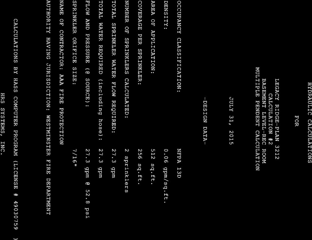
13 SPRINKLER SYSTEM HYDRAULIC ANALYSIS Page 2 DATE: 8/13/2015 C:\HASS78\CALCS\LEGACY RIDGE\3212\CALC2.SDF JOB TITLE: LEGACY RIDGE-PLAN 3212-CALC 2 WATER SUPPLY DATA SOURCE STATIC RESID. FLOW AVAIL. TOTAL REQ'D NODE PRESS. DEMAND PRESS. TAG (PSI) (PSI) (GPM) (PSI) (GPM) (PSI) SRC AGGREGATE FLOW ANALYSIS: TOTAL FLOW AT SOURCE 27.3 GPM TOTAL HOSE STREAM ALLOWANCE AT SOURCE 0.0 GPM OTHER HOSE STREAM ALLOWANCES 0.0 GPM TOTAL DISCHARGE FROM ACTIVE SPRINKLERS 27.3 GPM NODE ANALYSIS DATA NODE TAG ELEVATION NODE TYPE PRESSURE DISCHARGE (FT) (PSI) (GPM) K= K= A B B B B TOR BOR MT MT SRC -3.0 SOURCE
14 SPRINKLER SYSTEM HYDRAULIC ANALYSIS Page 3 DATE: 8/13/2015 C:\HASS78\CALCS\LEGACY RIDGE\3212\CALC2.SDF JOB TITLE: LEGACY RIDGE-PLAN 3212-CALC 2 PIPE DATA PIPE TAG Q(GPM) DIA(IN) LENGTH PRESS. END ELEV. NOZ. PT DISC. VEL(FPS) HW(C) (FT) SUM. NODES (FT) (K) (PSI) (GPM) FL/FT (PSI) Pipe: PL PF FTG 3E PE 0.0 B TL PV Pipe: PL PF FTG 2T PE 0.0 B TL PV Pipe: PL PF 0.0 A FTG E PE 4.8 B TL PV Pipe: PL 8.00 PF 0.8 B FTG ---- PE 0.0 B TL 8.00 PV Pipe: 10A PL 9.00 PF 1.1 B FTG ---- PE 0.0 B TL 9.00 PV Pipe: PL PF 0.0 B FTG ET PE TL PV Pipe: PL 6.00 PF FTG E PE 0.0 B TL PV Pipe: PL PF 2.0 B FTG 2E PE 0.0 TOR TL PV Pipe: PL 7.00 PF 0.6 TOR FTG CG PE 3.0 BOR TL PV Pipe: 23A PL PF 17.4 BOR FTG E PE 0.9 MT TL PV Pipe: 23B FIXED PRESSURE LOSS DEVICE MT psi, 27.3 gpm MT Pipe: PL PF 10.1 MT FTG 4ETG PE 1.3 SRC -3.0 SRCE 52.8 (N/A) TL PV
15 SPRINKLER SYSTEM HYDRAULIC ANALYSIS Page 4 DATE: 8/13/2015 C:\HASS78\CALCS\LEGACY RIDGE\3212\CALC2.SDF JOB TITLE: LEGACY RIDGE-PLAN 3212-CALC 2 NOTES (HASS): (1) Calculations were performed by the HASS 7.9 computer program under license no granted by HRS Systems, Inc LaVista Road Tucker, GA (2) The system has been calculated to provide an average imbalance at each node of gpm and a maximum imbalance at any node of gpm. (3) Total pressure at each node is used in balancing the system. Maximum water velocity is 11.3 ft/sec at pipe 23A1. (4) PIPE FITTINGS TABLE Pipe Table Name: CUSTOM.PIP PAGE: K MATERIAL: CT-K HWC: 150 Diameter Equivalent Fitting Lengths in Feet (in) E T F R C S G N Ell Tee 45-Ell TeeRun Couplg SwgChk GatVlv NPTee PAGE: P MATERIAL: CPVC HWC: 150 Diameter Equivalent Fitting Lengths in Feet (in) E T L C R G B A D Ell Tee Lell SwgChk Rtee N
16 SPRINKLER SYSTEM HYDRAULIC ANALYSIS Page 5 DATE: 8/13/2015 C:\HASS78\CALCS\LEGACY RIDGE\3212\CALC2.SDF JOB TITLE: LEGACY RIDGE-PLAN 3212-CALC 2 G A U G E WATER SUPPLY ANALYSIS Static: psi Resid: psi Flow: gpm LEGEND FLOW (GPM) P R E S S U R E ( p s i ) 1 2 B A Available pressure gpm Required pressure gpm A. Source Supply Curve B. System Demand Curve 1 2
17 SPRINKLER SYSTEM HYDRAULIC ANALYSIS Page 6 DATE: 8/13/2015 C:\HASS78\CALCS\LEGACY RIDGE\3212\CALC2.SDF JOB TITLE: LEGACY RIDGE-PLAN 3212-CALC 2 WATER SUPPLY CURVE \\ \\ \\ \\ 90+ \\\ \\ \\ \\ 81+ * < gpm Flow Test Point P 72+ R E S S 63+ U R E 54+ ( X P S I 45+ ) ============================== 18+ LEGEND " " X = Required Water Supply " gpm " 9+ " 0 = Available Water Supply " gpm " " FLOW (GPM)

18
19 SPRINKLER SYSTEM HYDRAULIC ANALYSIS Page 2 DATE: 8/13/2015 C:\HASS78\CALCS\LEGACY RIDGE\3212\CALC3.SDF JOB TITLE: LEGACY RIDGE-PLAN 3212-CALC 3 WATER SUPPLY DATA SOURCE STATIC RESID. FLOW AVAIL. TOTAL REQ'D NODE PRESS. DEMAND PRESS. TAG (PSI) (PSI) (GPM) (PSI) (GPM) (PSI) SRC AGGREGATE FLOW ANALYSIS: TOTAL FLOW AT SOURCE 20.0 GPM TOTAL HOSE STREAM ALLOWANCE AT SOURCE 0.0 GPM OTHER HOSE STREAM ALLOWANCES 0.0 GPM TOTAL DISCHARGE FROM ACTIVE SPRINKLERS 20.0 GPM NODE ANALYSIS DATA NODE TAG ELEVATION NODE TYPE PRESSURE DISCHARGE (FT) (PSI) (GPM) A B B B K= B TOR BOR MT MT SRC -3.0 SOURCE
20 SPRINKLER SYSTEM HYDRAULIC ANALYSIS Page 3 DATE: 8/13/2015 C:\HASS78\CALCS\LEGACY RIDGE\3212\CALC3.SDF JOB TITLE: LEGACY RIDGE-PLAN 3212-CALC 3 PIPE DATA PIPE TAG Q(GPM) DIA(IN) LENGTH PRESS. END ELEV. NOZ. PT DISC. VEL(FPS) HW(C) (FT) SUM. NODES (FT) (K) (PSI) (GPM) FL/FT (PSI) Pipe: PL PF 0.0 A FTG E PE 4.8 B TL PV Pipe: PL 8.00 PF 0.0 B FTG ---- PE 0.0 B TL 8.00 PV Pipe: 10A PL 9.00 PF 0.0 B FTG ---- PE 0.0 B TL 9.00 PV Pipe: PL PF 2.2 B FTG ET PE TL PV Pipe: PL 6.00 PF FTG E PE 0.0 B TL PV Pipe: PL PF 1.1 B FTG 2E PE 0.0 TOR TL PV Pipe: PL 7.00 PF 0.3 TOR FTG CG PE 3.0 BOR TL PV Pipe: 23A PL PF 9.8 BOR FTG E PE 0.9 MT TL PV Pipe: 23B FIXED PRESSURE LOSS DEVICE MT psi, 20.0 gpm MT Pipe: PL PF 5.7 MT FTG 4ETG PE 1.3 SRC -3.0 SRCE 44.9 (N/A) TL PV NOTES (HASS): (1) Calculations were performed by the HASS 7.9 computer program under license no granted by HRS Systems, Inc LaVista Road Tucker, GA (2) The system has been calculated to provide an average imbalance at each node of gpm and a maximum imbalance at any node of gpm.
21 SPRINKLER SYSTEM HYDRAULIC ANALYSIS Page 4 DATE: 8/13/2015 C:\HASS78\CALCS\LEGACY RIDGE\3212\CALC3.SDF JOB TITLE: LEGACY RIDGE-PLAN 3212-CALC 3 (3) Total pressure at each node is used in balancing the system. Maximum water velocity is 8.3 ft/sec at pipe 24. (4) PIPE FITTINGS TABLE Pipe Table Name: CUSTOM.PIP PAGE: K MATERIAL: CT-K HWC: 150 Diameter Equivalent Fitting Lengths in Feet (in) E T F R C S G N Ell Tee 45-Ell TeeRun Couplg SwgChk GatVlv NPTee PAGE: P MATERIAL: CPVC HWC: 150 Diameter Equivalent Fitting Lengths in Feet (in) E T L C R G B A D Ell Tee Lell SwgChk Rtee N
22 SPRINKLER SYSTEM HYDRAULIC ANALYSIS Page 5 DATE: 8/13/2015 C:\HASS78\CALCS\LEGACY RIDGE\3212\CALC3.SDF JOB TITLE: LEGACY RIDGE-PLAN 3212-CALC 3 G A U G E WATER SUPPLY ANALYSIS Static: psi Resid: psi Flow: gpm LEGEND FLOW (GPM) P R E S S U R E ( p s i ) 1 2 B A Available pressure gpm Required pressure gpm A. Source Supply Curve B. System Demand Curve 1 2
23 SPRINKLER SYSTEM HYDRAULIC ANALYSIS Page 6 DATE: 8/13/2015 C:\HASS78\CALCS\LEGACY RIDGE\3212\CALC3.SDF JOB TITLE: LEGACY RIDGE-PLAN 3212-CALC 3 WATER SUPPLY CURVE \\ \\ \\ \\ 90+ \\\ \\ \\ \\ 81+ * < gpm Flow Test Point P 72+ R E S S 63+ U R E 54+ ( P S I 45X ) ============================== 18+ LEGEND " " X = Required Water Supply " gpm " 9+ " 0 = Available Water Supply " gpm " " FLOW (GPM)
 Total adjustment.")
 2.")
24 Bulletin 006 Rev. F Model RFC30 (SIN RA0611) Model RFC43 (SIN RA0612) Model RFC49 (SIN RA0616) Residential Flat Concealed s Bulletin 006 Rev. F A Residential Flat Concealed engineered for a minimum design density of 0.05 gpm/ft 2 with low GPM requirements. Features Very low water flow requirements. ½ (13mm) Total adjustment. Thread-On/Thread-Off or Push-On/Thread Off cover attachment option. Smooth aesthetic ceiling profile. Available in brass, chrome and black plated or painted finishes. Listings & Approval 1. Listed by Underwriters Laboratories, and certified by UL for Canada (culus) 2. NYC MEA E UL Listing Categories Residential Automatic s UL Guide Number VKKW Product Description Model RFC30, RFC43 and RFC49 Concealed Residential s are fast response residential fusible solder link automatic sprinklers. Residential sprinklers differ from standard sprinklers primarily in their response time and water distribution patterns. Model RFC30, RFC43 and RFC49 sprinklers discharge water in a hemispherical pattern below the sprinkler deflector. Residential distribution patterns are higher and generally contain a finer droplet size than standard sprinkler patterns. The combination of speed of operation and high discharge pattern required for residential sprinklers has demonstrated, in fire testing, an ability for controlling residential fires, and thereby providing significant evacuation time for occupants. The RFC30, RFC43 and RFC49 s provide the best form of fire protection by combining an attractive appearance and ½ (13mm) of cover adjustment for ease of installation. The small diameter cover plate is easily and positively attached and blends into the ceiling, concealing the most dependable fire protection available, an automatic sprinkler system. The RFC30, RFC43 and RFC49 are UL Listed Residential s to be installed in the residential portions of any occupancy in accordance with NFPA 13, 13R, & 13D. The RFC30, RFC43 and RFC49 can reduce the need for precise cutting of drop nipples. The threaded cover plate assembly can be adjusted without tools to fit accurately against the ceiling. The fire protection system need not be shut down to adjust or remove the cover plate assembly. Application and Installation The RFC30, RFC43 and RFC49, for residential installations, use a 165 F (74 C) fusible solder link in a tuning fork style sprinkler frame with a drop-down deflector. This assembly is recessed into the ceiling and concealed by a flat cover plate. The cover plate is attached to the skirt, using 135 F (57 C) ordinary temperature classification solder. When the ceiling temperature rises, the solder holding the cover plate releases the cover allowing the deflector to drop into position and exposing the sprinkler inside to The Reliable Automatic Co., Inc., 103 Fairview Park Drive, Elmsford, New York 10523
25 ceiling temperature. The subsequent operation of the solder link opens the waterway and causes the deflector to drop into position to distribute the discharging water in a hemispherical pattern below the sprinkler deflector. Any adjustment of thread engagement between the cover plate and cup will assure that the drop-down deflector is properly located below the ceiling. The residential distribution pattern contains a finer droplet size than a standard sprinkler, and the pattern produces significantly higher wall wetting. After a 2 5 /8 inch diameter hole is cut in the ceiling, the sprinkler is to be installed with the Model FC Wrench. When installing a sprinkler, the wrench is first positioned into the sprinkler/cup assembly and around the hexagonal body of the sprinkler frame. The Wrench must bottom out against the cup in order to ensure proper, safe installation. The sprinkler is then tightened into the pipe fitting. When inserting or removing the wrench from the sprinkler/cup assembly, care should be taken to prevent damage to the sprinkler. DO NOT WRENCH ON ANY OTHER PART Temperature Rating Cover Plate Ambient Temp. 165 F/74 C 135 F/57 C 100 F/38 C Installation Data: RFC30 (SIN RA0611) Thread Size inch (mm) ½ (15mm) ½ (15mm) Note: 1 bar = 100 Kpa K Factor Spacing ft. (m) 12 x 12 (3.6x3.6) 14 x 14 (4.3x4.3) Installation Data: RFC43 (SIN RA0612) Thread Size inch (mm) ½ (15mm) ½ (15mm) ½ (15mm) ½ (15mm) ½ (15mm) Note: 1 bar = 100 Kpa K Factor Spacing ft. (m) 12 x 12 (3.6x3.6) 14 x 14 (4.3x4.3) 16 x 16 (4.9x4.9) 18 x 18 (5.5x5.5) 20 x 20 (6.0x6.0) Installation Data: RFC49 (RA0616) Thread Size inch (mm) ½ (15mm) ½ (15mm) ½ (15mm) ½ (15mm) ½ (15mm) Note: 1 bar = 100 Kpa K Factor Spacing ft. (m) 12 x 12 (3.6x3.6) 14 x 14 (4.3x4.3) 16 x 16 (4.9x4.9) 18 x 18 (5.5x5.5) 20 x 20 (6.0x6.0) Maximum Distance to Wall ft. (m) 6 (1.83) 7 (2.13) Maximum Distance to Wall ft. (m) 6 (1.83) 7 (2.13) 8 (2.43) 9 (2.74) 10 (3.05) Maximum Distance to Wall ft. (m) 6 (1.83) 7 (2.13) 8 (2.43) 9 (2.74) 10 (3.05) 2. OF THE SPRINKLER/CUP ASSEMBLY. MODEL RFC30, RFC43 AND RFC49 CONCEALED SPRINKLERS MUST BE INSTALLED ONLY WITH 135 F RATED COVERS. Note: A leak tight ½ NPT (R1/2) sprinkler joint can be obtained with a torque of 8-18 ft-lbs (10,8-24,4 N-m). Do not tighten sprinklers over maximum recommended torque. It may cause leakage or impairment of the sprinklers. Cover assemblies provide up to 1 /2 (13mm) of adjustment. Turn the cover clockwise until the flange is in contact with the ceiling. For the push-on/thread-off option, the cover assembly is pushed onto the cup and final adjustment is made by turning the cover clockwise until the skirt flange makes full contact with the ceiling. Cover removal requires turning in the counter-clockwise direction. In ceilings that have a plenum space above the sprinkler, the plenum space may have neutral or negative pressurization but must not be positively pressurized. Inspect all sprinklers after installation to ensure that the gap between the cover plate and ceiling and the 4 slots in the cup are all open and free from any air flow impediment. Minimum Distance between sprinklers ft. (m) 8 (2.43) 8 (2.43) Minimum Distance between sprinklers ft. (m) 8 (2.43) 8 (2.43) 8 (2.43) 8 (2.43) 8 (2.43) Minimum Distance between sprinklers ft. (m) 8 (2.43) 8 (2.43) 8 (2.43) 8 (2.43) 8 (2.43) FOR SLOPED CEILING APPLICATIONS SEE RASCO BULLETIN 035. Minimum Required Discharge Flow gpm (Lpm) 9 (34.1) 10 (37.8) Press. psi (bar) 9.0 (0.62) 11 (0.76) Minimum Required Discharge Flow gpm (Lpm) 12 (45) 13 (49) 13 (49) 18 (68) 21 (79) Press. psi (bar) 7.8 (0.54) 9.1 (0.63) 9.1 (0.63) 17.5 (1.21) 23.8 (1.64) Minimum Required Discharge Flow gpm (Lpm) 13 (49) 13 (49) 13 (49) 17 (64.3) 20 (75.7) Press. psi (bar) 7.0 (0.48) 7.0 (0.48) 7.0 (0.48) 12.0 (0.83) 16.7 (1.14)

26 Maintenance Model RFC30, RFC43 and RFC49 Concealed s should be inspected quarterly and the sprinkler system maintained in accordance with NFPA 25. Do not clean sprinklers with soap and water, ammonia or any other cleaning fluids. Remove dust by using a soft brush or gentle vacuuming. Remove any sprinkler cover plate assembly which has been painted (other than factory applied) or damaged in any way. A stock of spare sprinklers should be maintained to allow quick replacement of damaged or operated sprinklers. Prior to installation, sprinklers should be maintained in the original cartons and packaging until used to minimize the potential for damage to sprinklers that would cause improper operation or non-operation. Model RFC30, RFC43 and RFC49 Residential Concealed Specification s shall be culus Listed low flow residential concealed sprinklers with drop-down deflector and adjustable flat cover plate engineered for a minimum design density of 0.05 gpm/ft 2. frame and deflector shall be of bronze frame construction having a ½ NPT thread. Thermal element shall consist of an approved black-painted beryllium-nickel fusible solder link with symmetric lever mechanism, maintaining a Teflon-coated Belleville spring washer and machined brass cap water seal assembly containing no plastic parts. K-factor shall be nominal 3.0 (44), 4.3 (62.4), and 4.91 (70) having a 5 / 16, 3 / 8 and 7 /16 orifice. Temperature rating shall be Ordinary 165 F (74 C); cover plate temperature rating to be 135 F (57 C). Cover plate assembly shall consist of a brass cover plate and copper alloy retainer flange allowing a ½ cover plate adjustment. Any secure engagement between the cover plate and the cup will assure that the drop-down deflector is properly located below the ceiling. A plastic protective cap shall be provided and factory installed inside the sprinkler cup to protect the drop-down sprinkler deflector from damage, which could occur during construction before the cover plate is installed. Standard cover finish: [Chrome] [White] [Specialty specify]. Residential concealed sprinklers shall be Reliable Model RFC30, SIN RA0611 (Bulletin 006), Model RFC43, SIN RA0612 (Bulletin 006) or Model RFC49, SIN RA0616 (Bulletin 006). Ordering Information Cover Plate Finishes (1) Specify: Model Cover Plate Finish Thread-On or Push-On Feature Standard Finishes Chrome White Special Application Finishes Bright Brass Black Plating Black Paint Off White Satin Chrome (1) Other colors and finishes available. Consult factory for details. Note: Paint or any other coatings applied over the factory finish will void all approvals and warranties. 3.

27 Reliable...For Complete Protection Reliable offers a wide selection of sprinkler components. Following are some of the many precision-made Reliable products that guard life and property from fire around the clock. Automatic sprinklers Flush automatic sprinklers Recessed automatic sprinklers Concealed automatic sprinklers Adjustable automatic sprinklers Dry automatic sprinklers Intermediate level sprinklers Open sprinklers Spray nozzles Alarm valves Retarding chambers Dry pipe valves Accelerators for dry pipe valves Mechanical sprinkler alarms Electrical sprinkler alarm switches Water flow detectors Deluge valves Detector check valves Check valves Electrical system emergency cabinets wrenches escutcheons and guards Inspectors test connections Sight drains Ball drips and drum drips Control valve seals Air maintenance devices Air compressors Pressure gaugesidentification signs Fire department connection The equipment presented in this bulletin is to be installed in accordance with the latest published Standards of the National Fire Protection Association, Factory Mutual Research Corporation, or other similar organizations and also with the provisions of governmental codes or ordinances whenever applicable. Productsmanufactured and distributed by Reliable have been protecting life and property for over 90 years, and are installed and serviced by the most highly qualified and reputable sprinkler contractors located throughout the United States, Canada and foreign countries. Manufactured by The Reliable Automatic Co., Inc. (800) Sales Offices (800) Sales Fax (914) Corporate Offices Internet Address Recycled Paper Revision lines indicate updated or new data. EG. Printed in U.S.A 02/11 P/N


 are fast response sprinklers combining excellent durability, high sensitivity glass-bulb and low profile decorative design. The F1 Res Horizontal Sidewall sprinklers (Figs.")

28 Bulletin 135 Rev. H Model F1 Residential s for Design Density of.05 gpm/ft 2 Bulletin 135 Rev. H Model F1 Res s engineered for the lowest flows to meet the minimum design density of.05 gpm/ft 2 Types: 1. F1 Res 30 Pendent 2. F1 Res 30 Recessed Pendent/F2 3. F1 Res 30 Recessed Pendent/FP 4. F1 Res 49 Pendent 5. F1 Res 49 Recessed Pendent/F1 6. F1 Res 49 Recessed Pendent/FP 7. F1 Res 58 Pendent 8. F1 Res 58 Recessed Pendent/F1 9. F1 Res 58 Recessed Pendent/FP 10. F1 Res 76 Pendent 11. F1 Res 76 Recessed Pendent/F1 12. F1 Res 76 Recessed Pendent/FP 13. F1 Res 30 CCP Pendent 14. F1 Res 49 CCP Pendent 15. F1 Res 58 CCP Pendent 16. F1 Res 76 CCP Pendent 17. F1 Res 44 HSW 18. F1 Res 44 Recessed HSW/F2 19. F1 Res 58 HSW 20. F1 Res 58 HSW Recessed HSW/F2 21. F1 Res 44 SWC Listings & Approvals 1. Listed by Underwriters Laboratories Inc. and UL Certified for Canada (culus) 2. NYC MEA E Slope Ceiling Approvals: Refer to Bulletin 035 s for.10 Density: Refer to Bulletin 176 UL Listing Category Residential Automatic UL Guide Number VKKW Patents US Patent No. 6,516,893 applies to the Model F1 Res 49 & 58 Pendent s Product Description Model F1 Res Pendent sprinklers (Figs. 1, 2, 3, & 4) are fast response sprinklers combining excellent durability, high sensitivity glass-bulb and low profile decorative design. The F1 Res Horizontal Sidewall sprinklers (Figs. 5, 6 & 7) are equally attractive when above ceiling piping cannot be used. F1 Res 30, 49, 58 & 76 Recessed Pendent / F1 F1 Res 30, 49, 58 & 76 CCP Pendent F1 Res 44 SWC F1 Res 30, 49, 58 & 76 Recessed Pendent / FP F1 Res 44 & 58 Recessed HSW/F2 The 3mm glass-bulb pendent sprinklers permit the efficient use of residential water supplies for sprinkler coverage in residential fire protection design. The low flow F1 Res sprinklers are specially engineered for fast thermal response to meet the sensitive fire protection application needs of the latest residential market standards (UL 1626 Standard). Upon fire conditions, rising heat causes a sprinkler s heat-sensitive glass-bulb to shatter, releasing the waterway for water flow onto the deflector, evenly distributing the discharged water to control a fire. Technical Data: Thermal Sensor: Nominal 3mm glass-bulb Frame : Brass Casting s Pressure Rating : 175 psi Factory Hydrostatically Tested to 500 psi Thread Size: ½ NPT (R½) K-Factor: 3.0 (Actual) - F1 Res 30 Pendent 4.9 (Actual) - F1 Res 49 Pendent 5.8 (Actual) - F1 Res 58 Pendent & HSW 7.6 (Actual) - F1 Res 76 Pendent 4.4 (Actual) - F1 Res 44 HSW Density: Minimum 0.05 gpm/ft 2 The Reliable Automatic Co., Inc., 103 Fairview Park Drive, Elmsford, New York 10523

29 Application Model F1 Res s are used for Residential Fire Protection according to UL 1626 Standard*. Be sure that orifice size, temperature rating, deflector style and sprinkler type are in accordance with the latest published standards of The National Fire Protection Association or the approving authority having jurisdiction. Installation Models F1 Res sprinklers are to be installed as shown. Model F1, F2 and FP Escutcheons, illustrated herewith, are the only recessed escutcheons to be used with Model F1 Res sprinklers. Use of any other recessed escutcheon will void all approvals and warranties. For installing Model F1 Res Pendent sprinklers use only the Model D sprinkler Model F1 Res 30, 49, 58 & 76 Pendent Model F1 Res 30 Recessed Pendent / F2 Model F1 Res 49, 58 & 76 Recessed Pendent / F1 F1 escutcheon, 3 /4 (19mm) adjustment Fig. 1 Fig. 2 Wrench; for installing Models F1 Res Recessed Pendent, CCP & SWC sprinklers use only the Model GFR2 sprinkler wrench; for installing Model F1 Res Recessed HSW sprinklers use only the Model GFR2 Wrench. Use of wrenches other than those specified may damage these sprinklers. Install F1 Res 44 with a ceiling to deflector distance of Flow arrow on deflector must point away from near wall and Top marking must face ceiling. Escutcheon*, F1 or F2, Data: Type Adjustment F1 3/4 (19.0) F2 1/2 (12.7) A Min.= 3 /4 (19.1) =1 1 /2 (38.1) Min.= 15 /16 (23.8) =1 1 /2 (38.1) Face of fitting to ceiling 3 /16-15 /16 ( ) 3 /16-11 /16 ( ) * Note: Escutcheons F1 or F2 may be used with Model F1 Res 49, 58 & 76 Recessed Pendent 2.
30 Technical Data: F1Res 30 Pendent and Recessed Pendent Thread Size ½ NPT (R½) Nominal Orifice 21 /64 (8.2) Temp. Rating Pressure Ambient Temp. F C psi (bar) F C Actual K Factor Length 175 (12) (57) Deflector - to - ceiling Maximum 1 (25mm) to 4 (100mm) Spacing ft (m) Flow gpm (Lpm) Pressure psi (bar) 12 x 12 (3,6 x 3,6) 8 (30.3) 7.0 (0,48) 14 x 14 (4,3 x 4,3) 10 (37.8) 11 (0,76) Identification Number (SIN) R3511 Technical Data: F1Res 49 Pendent and Recessed Pendent. Thread Size ½ NPT (R½) Nominal Orifice 7 /16 (11) Temp. Rating Pressure Ambient Temp. F C psi (bar) F C (12) Actual K Factor Length (57) Deflector - to - ceiling Maximum 1 (25mm) to 4 (100mm) Deflector - to - ceiling Maximum 4 (100mm) to 8 (203mm) Spacing ft (m) Flow gpm (Lpm) Pressure psi (bar) 12 x 12 (3,6 x 3,6) 13 (49) 7.0 (0,48) 14 x 14 (4,3 x 4,3) 13 (49) 7.0 (0,48) 16 x 16 (4,9 x 4,9) 13 (49) 7.0 (0,48) 18 x 18 (5,5 x 5,5) 17 (64.3) 12.0 (0,83) 20 x 20 (6,1 x 6,1) 13 (75.7) 16.7 (1,14) Identification Number (SIN) R3516 Spacing ft (m) Flow gpm (Lpm) Pressure psi (bar) 12 x 12 (3,6 x 3,6) 15 (57) 9.4 (0,65) 14 x 14 (4,3 x 4,3) 16 (60.5) 10.6 (0,73) 16 x 16 (4,9 x 4,9) 17 (64.3) 12.0 (0,83) 18 x 18 (5,5 x 5,5) 19 (72) 15.0 (1,0) 20 x 20 (6,1 x 6,1) 22 (83.2) 20.2 (1,4) Identification Number (SIN) R3516 *Note: The F1 Res 49 pendent and recessed pendent residential sprinklers can be installed per NFPA 13 in beamed ceilings meeting the following criteria: 1. Maximum beam depth = 7 (178mm) 2. Beam spacing at or greater than 7.5 ft. (2.3m) on center. Technical Data: F1Res 58 Pendent and Recessed Pendent. Thread Size ½ NPT (R½) Nominal Orifice ½ (13) Temp. Rating Pressure Ambient Temp. F C psi (bar) F C (12) Actual K Factor Length (57) Spacing ft (m) Flow gpm (Lpm) Pressure psi (bar) 12 x 12 (3,6 x 3,6) 16 (61) 7.6 (0,53) 14 x 14 (4,3 x 4,3) 16 (61) 7.6 (0,53) 16 x 16 (4,9 x 4,9) 16 (61) 7.6 (0,53) 18 x 18 (5,5 x 5,5) 19 (72) 10.8 (0,75) 20 x 20 (6,1 x 6,1) 22 (83.3) 14.4 (1,0) Ceiling -to- Deflector 1-4 (25-100) Identification Number (SIN) R
 F C 155 175 68 79 175 (12) 100 150 38 66 K Factor Length 7.6 2.25 (57) Spacing ft (m) Flow gpm (Lpm) Pressure psi (bar) 12 x 12 (3,6 x 3,6) 21 (79.5) 7.")
31 Technical Data: F1 Res 76 Pendent and Recessed Pendent Thread Size 3 /4 NPT (R½) Nominal Orifice 17 /32 (13.5) Temp. Rating Pressure Ambient Temp. F C psi (bar) F C (12) K Factor Length (57) Spacing ft (m) Flow gpm (Lpm) Pressure psi (bar) 12 x 12 (3,6 x 3,6) 21 (79.5) 7.6 (0,53) 14 x 14 (4,3 x 4,3) 21 (79.5) 7.6 (0,53) 16 x 16 (4,9 x 4,9) 21 (79.5) 7.6 (0,53) 18 x 18 (5,5 x 5,5) 21 (79.5) 7.6 (0,53) 20 x 20 (6,1 x 6,1) 23 (87.1) 9.2 (0,63) Identification Number (SIN) R7618 Model F1 Res 30, 49, 58 & 76 CCP Pendent Model F1 Res 30, 49, 58 & 76 Recessed Pendent / FP FP push-on/thread-off escutcheon Fig. 3 Fig. 4 Note: The F1 Res 76 will use a 1 x ¾ reducer. 4.
32 Technical Data: F1Res 30 CCP Pendent and Recessed Pendent/FP Thread Size ½ NPT (R½) Nominal Orifice Spacing ft (m) Temp. Rating CCP Assembly Temp. Rating Pressure Ambient Temp. F C F C psi (bar) F C K Factor Length 21 /64 (8.2) (12) (57) Flow gpm (Lpm) Pressure psi (bar) 12 x 12 (3,6 x 3,6) 8 (30.3) 7.0 (0,48) 14 x 14 (4,3 x 4,3) 11 (41.6) 13.4 (0,92) Identification Number (SIN) R3511 Technical Data: F1Res 49 CCP Pendent and Recessed Pendent/FP Thread Size ½ NPT (R½) Nominal Orifice Inch (mm) Temp. Rating CCP Assembly Temp. Rating Pressure psi (bar) Ambient Temp. F C F C F C K Factor Length Inch (mm) 7 /16 (11) (12) (57) Spacing ft (m) Flow gpm (Lpm) Pressure psi (bar) 12 x 12 (3,6 x 3,6) 13 (49) 7.0 (0,48) 14 x 14 (4,3 x 4,3) 13 (49) 7.0 (0,48) 16 x 16 (4,9 x 4,9) 14 (53) 8.2 (0,56) 18 x 18 (5,5 x 5,5) 18 (68.1) 13.5 (0,93) 20 x 20 (6,1 x 6,1) 20 (75.7) 16.7 (1,14) Identification Number (SIN) R3516 Technical Data: F1Res 58 CCP Pendent and Recessed Pendent/FP Thread Size ½ NPT (R½) Nominal Orifice Spacing ft (m) Temp. Rating CCP Assembly Temp. Rating Pressure Ambient Temp. F C F C psi (bar) F C CCP Options Data: A B Cover Adjustment CCP Height 1 15 /2 (12.7) /16 (24) 5 /16 (7.9) 3 /4 (19) FP Data A : A FP Position Recessed 7 /16 (11) 15 Min. Recessed /16 (24) Note: s shown in Fig. 3 and Fig. 4 are not suitable for installation in ceilings which have positive pressure in the space above. K Factor Length 1 /2 (13) (12) (57) Flow gpm (Lpm) Pressure psi (bar) 12 x 12 (3,6 x 3,6) 16 (61) 7.6 (0,53) Identification Number (SIN) 14 x 14 (4,3 x 4,3) 16 (61) 7.6 (0,53) 16 x 16 (4,9 x 4,9) 16 (61) 7.6 (0,53) R x 18 (5,5 x 5,5) 19 (72) 10.8 (0,75) 20 x 20 (6,1 x 6,1) 22 (83.3) 14.4 (1,0) Technical Data: F1Res 76 CCP Pendent and Recessed Pendent/FP Thread Size 3 /4 NPT (R 3 /4) Nominal Orifice 17 /32 (13.5) Temp. Rating CCP Assembly Temp. Rating Pressure Ambient Temp. F C F C psi (bar) F C (12) K Factor Length (57) Spacing ft (m) Flow gpm (Lpm) Pressure psi (bar) 12 x 12 (3,6 x 3,6) 21 (79.5) 7.6 (0,53) 14 x 14 (4,3 x 4,3) 21 (79.5) 7.6 (0,53) 16 x 16 (4,9 x 4,9) 21 (79.5) 7.6 (0,53) 18 x 18 (5,5 x 5,5) 22 (83.3) 8.4 (0,58) 20 x 20 (6,1 x 6,1) 25 (94.6) 10.8 (0,74) Identification Number (SIN) R
 Ambient Temp. F C F C 155 175 68 79 175 (12) 100 150 38 66 K Factor Length 4.4 2.")
33 Model F1 Res 44 & 58 HSW Model F1 Res 44 & 58 Recessed HSW/F2 Fig. 5 F2 escutcheon, 1/2 (13mm) adjustment Technical Data: F1Res 44 HSW & HSW/F2 Thread Size ½ NPT (R½) Nominal Orifice 3 /8 (10) Temp. Rating Pressure psi (bar) Ambient Temp. F C F C (12) K Factor Length (62) Escutcheon, F2, Data: Type Adjustment F2 1 /2 (13) Face of Fitting to wall 3 /16-11 /16 ( ) Spacing ft (m) 12 x 12 (3,6 x 3,6) A Ceiling to Deflector Temp. Rating F ( C) Flow gpm (Lpm) Pressure psi (bar) 155 (68) 175 (79) 12 (45,4) 7.5 (0,52) 14 x 14 (4,3 x 4,3) 155 (68) 175 (79) 14 (53,0) 10.2 (0,71) 16 x 16 (4,9 x 4,9) 16 x 18 (4,9 x 5,5) 4-6 ( ) 155 (68) 155 (68) 175 (79) 175 (79) 16 (60,6) 18 (68,1) 13.3 (0,92) 16.8 (1,16) 18 x 18 (5,5 x 5,5) 155 (68) 175 (79) 19 (72,0) 18.7 (1,29) 16 x 20 (4,9 x 6,1) 155 (68) 175 (79) 23 (87,1) 27.4 (1,89) 12 x 12 (3,6 x 3,6) 155 (68) 175 (79) 14 (53,0) 10.2 (0,71) 14 x 14 (4,3 x 4,3) 155 (68) 175 (79) 16 (60,6) 13.3 (0,92) x 16 (4,9 x 4,9) 155 (68) 175 (79) 17 (64,4) 15.0 (1,04) ( ) 16 x 18 (4,9 x 5,5) 155 (68) 175 (79) 20 (75,7) 20.7 (1,43) 16 x 20 (4,9 x 6,1) 155 (68) 175 (79) 23 (87,1) 27.4 (1,89) Identification Number (SIN) R
34 Technical Data: F1Res 58 HSW & HSW/F2 Thread Size ½ NPT (R½) Nominal Orifice 1 /2 (13) Temp. Rating Pressure psi (bar) Ambient Temp. F C F C (12) K Factor Length (62) Escutcheon, F2, Data: Type Adjustment F2 1 /2 (13) Face of Fitting to wall 3 /16-11 /16 ( ) Spacing ft (m) 12 x 12 (3,6 x 3,6) A Ceiling to Deflector Temp. Rating F ( C) Flow gpm (Lpm) Pressure psi (bar) 155 (68) 175 (79) 16 (60,6) 7.6 (0,53) 14 x 14 (4,3 x 4,3) 155 (68) 175 (79) 18 (68,2) 9.7 (0,67) x 16 (4,9 x 4,9) 155 (68) 175 (79) 21 (79,5) 13.2 (0,91) ( ) 16 x 18 (4,9 x 5,5) 155 (68) 175 (79) 25 (94,7) 18.6 (1,28) 16 x 20 (4,9 x 6,1) 155 (68) 175 (79) 29 (109,8) 25 (1,73) 12 x 12 (3,6 x 3,6) 155 (68) 175 (79) 22 (83,3) 14.4 (1,0) 14 x 14 (4,3 x 4,3) (68) 175 (79) 22 (83,3) 14.4 (1,0) 16 x 16 (4,9 x 4,9) ( ) 155 (68) 175 (79) 26 (98,4) 20.1 (1,39) 16 x 18 (4,9 x 5,5) 155 (68) 175 (79) 31 (117,4) 28.6 (1,97) Identification Number (SIN) R3533 Model F1 Res 44 SWC Technical Data: F1Res 44 SWC Thread Size ½ NPT (R½) Nominal Orifice Temp. Rating Cover Temp. Rating Pressure psi (bar) Ambient Temp. F C F C F C K Factor Fig. 6 Length 3 /8 (10) (12) (62) Spacing ft (m) A Ceiling to Deflector Flow gpm (Lpm) Pressure psi (bar) 12 x 12 (3,6 x 3,6) 13 (49,2) 8.7 (0,60) 14 x 14 (4,3 x 4,3) 14 (53,0) 10.2 (0,71) x 16 (4,9 x 4,9) 17 (64,3) 15.0 (1,1) ( ) 16 x 18 (4,9 x 5,5) 19 (71,8) 18.7 (1,13) 16 x 20 (4,9 x 6,1) 23 (87,1) 27.4 (1,89) 12 x 12 (3,6 x 3,6) 14 (52,9) 10.2 (0,71) 14 x 14 (4,3 x 4,3) (56,7) 11.7 (0,81) 16 x 16 (4,9 x 4,9) ( ) 18 (68,1) 16.8 (1,16) 16 x 18 (4,9 x 5,5) 20 (75,6) 20.7 (1,43) 7. Identification Number (SIN) R3531
35 Maintenance Model F1 Res 30, 49, F1 Res 58, F1 Res 76 and F1 Res 44 s should be inspected quarterly, and the sprinkler system maintained in accordance with NFPA 25, 13, 13D, and 13R. Do not clean sprinkler with soap and water, Ammonia or any other cleaning fluids. Remove dust by using a soft brush or gentle vacuuming. Remove any sprinkler which has been painted (other than factory applied) or damaged in any way. A stock of spare sprinklers should be maintained to allow quick replacement of damaged or operated sprinklers. Prior to installation, sprinklers should remain in the original cartons and packaging until used. This will minimize the potential for damage to sprinklers that could cause improper operation or non-operation. Model F1 Res 30, 49 & 58 Pendent Specifications s shall be [culus Listed] [New York City MEA Approved ( E)] low flow residential pendent sprinklers engineered to provide a minimum design density of 0.05 gpm/ft 2 over the listed coverage area. Listed flows as specified by the manufacturer s technical data sheets are to be used. Residential sprinklers shall be installed in conformance with the manufacturer s installation guidelines and the applicable installation standard. Where pendent residential sprinklers are installed under sloped ceilings having a pitch from [4/12] to [8/12], the sprinklers shall be listed for such use. Deflector-to-ceiling distance listing shall be 1 to 8 maximum. frame and deflector shall be of bronze frame construction having a ½ NPT thread. Water seal assembly shall consist of a Teflon-coated Belleville spring washer with top-loaded extruded or cold head cup with 3 mm glass bulb containing no plastic parts, and having a temperature rating of [155 F (68 C)] [175 F (79 C)]. s shall have a nominal K-factor of 3.0, 4.9 and 5.8. Standard finish: [Bronze] [Chrome-plated] [White Polyester] [Special finish specify]. Residential pendent sprinklers shall be Reliable Model F1 Res 30, 49 & 58, SIN R3511, R3516 & R3513 (Bulletin 135). Model F1 Res 49 & 58 Recessed Pendent/F1, Model F1 Res 30, 49 & 58 Recessed Pendent/F2, Model F1 Res 30, 49 & 58 Recessed Pendent/FP s shall be [culus Listed] [New York City MEA Approved ( E)] low flow residential recessed pendent sprinklers engineered to provide a minimum design density of 0.05 gpm/ft 2 over the listed coverage area. Listed flows as specified by the manufacturer s technical data sheets are to be used. Residential sprinklers shall be installed in conformance with the manufacturer s installation guidelines and the applicable installation standard. Where pendent residential sprinklers are installed under sloped ceilings having a pitch from [4/12] to [8/12], the sprinklers shall be listed for such use. Deflectorto-ceiling distance listing shall be 1 to 8 maximum. frame and deflector shall be of bronze frame construction having a ½ NPT thread. Water seal assembly shall consist of a Teflon-coated Belleville spring washer with top-loaded extruded or cold head cup with 3 mm glass bulb containing no plastic parts, and having a temperature rating of [155 F (68 C)] [175 F (79 C)]. s shall have a nominal K-factor of 3.0, 4.9 & 5.8. Standard finish: [Bronze] [Chrome-plated] [White Polyester] [Special finish specify]. Recessed escutcheon assembly shall be a steel, two-piece escutcheon [with ½ adjustment (Model F2)] [with ¾ adjustment (Model F1)] [of push-on and thread off design with ½ adjustment (Model FP)]. Standard finish shall be [brass][bright chrome] [white painted]. Residential recessed pendent sprinklers shall be Reliable [Model F1 Res 30, 49 & 58 Recessed Pendent/F1] [Model F1 Res 30, 49 & 58 Recessed Pendent/F2] [Model F1 Res 30, 49 & 58 Recessed Pendent/FP] SIN R3511, R3516 & R3513 (Bulletin 135). Model F1 Res 30, 49 & 58 CCP Pendent (Concealed) s shall be [culus Listed] [New York City MEA Approved ( E)] low flow residential concealed sprinklers engineered to provide a minimum design density of 0.05 gpm/ft 2 over the listed coverage area. Listed flows as specified by the manufacturer s technical data sheets are to be used. Residential sprinklers shall be installed in conformance with the manufacturer s installation guidelines and the applicable installation standard. Where pendent residential sprinklers are installed under sloped ceilings having a pitch from [4/12] to [8/12], the sprinklers shall be listed for such use. frame and deflector shall be of bronze frame construction having a ½ NPT thread. Water seal assembly shall consist of a Teflon-coated Belleville spring washer with top-loaded extruded or cold head cup with 3 mm glass bulb containing no plastic parts, and having a temperature rating of 155 F (68 C). Cover plate assembly shall consist of a brass cover plate and copper alloy retainer flange. Method of attaching the cover plate to the sprinkler cup shall be a pushon and thread-off design allowing a ½ cover plate adjustment. Cover plate temperature rating shall be 135 F (57 C). A plastic protective cap shall be provided and factory installed inside the sprinkler cup to protect the sprinkler from damage, which could occur during construction before the cover plate is installed. Standard cover plate finish: [White] [Custom Color specify]. ]. Concealed pendent sprinklers shall be Reliable Model F1 Res 30, 49 & 58 CCP, SIN R3511, R3516 & R3513 (Bulletin 135). Model F1 Res 44 Horizontal Sidewall Residential Specifications s shall be [culus Listed] [New York City MEA Approved ( E)] low flow residential horizontal sidewall sprinklers engineered to provide a minimum design density of 0.05 gpm/ft 2 over the listed coverage area. Listed flows as specified by the manufacturer s technical data sheets are to be used. Residential sprinklers shall be installed in conformance with the manufacturer s installation guidelines and the applicable installation standard. Where horizontal sidewall residential sprinklers are installed under sloped ceilings having a pitch from [4/12] to [8/12], the sprinklers shall be listed for such use. frame and deflector shall be of bronze frame construction having a ½ NPT thread. Water seal assembly shall consist of a Teflon-coated Belleville spring washer with top-loaded extruded or cold head cup with 3 mm glass bulb containing no plastic parts, and having a temperature rating of [155 F (68 C)] [175 F (79 C)]. s shall have a nominal K-factor of 4.4 (62.8). Standard finish: [Bronze] [Chrome-plated] [White Polyester] [Special finish specify]. Residential horizontal sidewall sprinklers shall be Reliable Model F1 Res 44, SIN R3531 (Bulletin 135). 8.
36 Model F1 Res 44 Recessed Horizontal Sidewall Use description for the Model F1 Res 44 horizontal sidewall sprinkler with the following modifications: Replace horizontal sidewall sprinkler with recessed horizontal sprinkler. Add: Recessed escutcheon assembly shall be a steel, two-piece escutcheon with ½ adjustment (Model F2). Standard finish shall be [brass][bright chrome] [white painted] [Special finish specify]. Residential recessed horizontal sidewall sprinklers shall be Reliable Model F1 Res 44/F2, SIN R3531 (Bulletin 135). Model F1 Res 76 Pendent s shall be [culus Listed] low flow residential pendent sprinklers engineered to provide a minimum design density of 0.05 gpm/ft 2 over the listed coverage area. Listed flows as specified by the manufacturer s technical data sheets are to be used. Residential sprinklers shall be installed in conformance with the manufacturer s installation guidelines and the applicable installation standard. frame and deflector shall be of bronze frame construction having a ¾ NPT thread. Water seal assembly shall consist of a Teflon-coated Belleville spring washer with machined or cold head cup with 3 mm glass bulb containing no plastic parts, and having a temperature rating of [155 F (68 C)] [175 F (79 C)]. s shall have a nominal K-factor of 7.6. Standard finish: [Bronze] [Chrome-plated] [White Polyester] [Special finish specify]. Residential pendent sprinklers shall be Reliable Model F1 Res 76, SIN R7618 (Bulletin 135). Model F1 Res 76 Recessed Pendent/F1, Model F1 Res 76 Recessed Pendent/F2, Model F1 Res 76 Recessed Pendent/FP s shall be [culus Listed] low flow residential recessed pendent sprinklers engineered to provide a minimum design density of 0.05 gpm/ft 2 over the listed coverage area. Listed flows as specified by the manufacturer s technical data sheets are to be used. Residential sprinklers shall be installed in conformance with the manufacturer s installation guidelines and the applicable installation standard. frame and deflector shall be of bronze frame construction having a ¾ NPT thread. Water seal assembly shall consist of a Teflon-coated Belleville spring washer with machined or cold head cup with 3 mm glass bulb containing no plastic parts, and having a temperature rating of [155 F (68 C)] [175 F (79 C)]. s shall have a nominal K-factor of 7.6. Standard finish: [Bronze] [Chrome-plated] [White Polyester] [Special finish specify]. Recessed escutcheon assembly shall be a steel, two-piece escutcheon [with ½ adjustment (Model F2)] [with ¾ adjustment (Model F1)] [of push-on and thread off design with ½ adjustment (Model FP)]. Standard finish shall be [brass][bright chrome] [white painted]. Residential recessed pendent sprinklers shall be Reliable [Model F1 Res 76 Recessed Pendent/ F1] [Model F1 Res 76 Recessed Pendent/F2] [Model F1 Res 76 Recessed Pendent/FP] SIN R7618 (Bulletin 135). Model F1 Res 76 CCP Pendent (Concealed) s shall be [culus Listed] low flow residential concealed sprinklers engineered to provide a minimum design density of 0.05 gpm/ft 2 over the listed coverage area. Listed flows as specified by the manufacturer s technical data sheets are to be used. Residential sprinklers shall be installed in conformance with the manufacturer s installation guidelines and the applicable installation standard. frame and deflector shall be of bronze frame construction having a ¾ NPT thread. Water seal assembly shall consist of a Teflon-coated Belleville spring washer with machined or cold head cup with 3 mm glass bulb containing no plastic parts, and having a temperature rating of 155 F (68 C). Cover plate assembly shall consist of a brass cover plate and copper alloy retainer flange. Method of attaching the cover plate to the sprinkler cup shall be a push-on and thread-off design allowing a ½ cover plate adjustment. Cover plate temperature rating shall be 135 F (57 C). A plastic protective cap shall be provided and factory installed inside the sprinkler cup to protect the sprinkler from damage, which could occur during construction before the cover plate is installed. Standard cover plate finish: [White] [Custom Color specify]. ]. Concealed pendent sprinklers shall be Reliable Model F1 Res 76 CCP, SIN R7618 (Bulletin 135). Finishes (1) Bronze Chrome Plated White and Black Polyester Coated Bright Brass Black Plated Black Paint Off White Satin Chrome Standard Finishes F1, F2, FP Escutcheons Brass Bright Chrome Plated White Painted Special Application Finishes F1, F2, Escutcheons Bright Brass Black Plated Black Paint Off White Satin Chrome Cover Plates White Painted Chrome Cover Plates Bright Brass Black Plated Black Paint Off White Satin Chrome (1) Other finishes and colors are available on special order. Consult factory for details. Note: Paint or any other coating applied over the factory finish will void all approvals and warranties. Ordering Information Specify: 1. Model 2. Type 3. Temperature Rating 4. Finish 5. Escutcheon Finish 6. Cover Plate Finish 9.
37 Reliable...For Complete Protection Reliable offers a wide selection of sprinkler components. Following are some of the many precision-made Reliable products that guard life and property from fire around the clock. Automatic sprinklers Flush automatic sprinklers Recessed automatic sprinklers Concealed automatic sprinklers Adjustable automatic sprinklers Dry automatic sprinklers Intermediate level sprinklers Open sprinklers Spray nozzles Alarm valves Retarding chambers Dry pipe valves Accelerators for dry pipe valves Mechanical sprinkler alarms Electrical sprinkler alarm switches Water flow detectors Deluge valves Detector check valves Check valves Electrical system emergency cabinets wrenches escutcheons and guards Inspectors test connections Sight drains Ball drips and drum drips Control valve seals Air maintenance devices Air compressors Pressure gaugesidentification signs Fire department connection The equipment presented in this bulletin is to be installed in accordance with the latest published Standards of the National Fire Protection Association, Factory Mutual Research Corporation, or other similar organizations and also with the provisions of governmental codes or ordinances whenever applicable. Productsmanufactured and distributed by Reliable have been protecting life and property for over 90 years, and are installed and serviced by the most highly qualified and reputable sprinkler contractors located throughout the United States, Canada and foreign countries. Manufactured by The Reliable Automatic Co., Inc. (800) Sales Offices (800) Sales Fax (914) Corporate Offices Internet Address Recycled Paper Revision lines indicate updated or new data. EG. Printed in U.S.A 09/10 P/N

38 Coverage to 16 ft. x 20 ft. (4.9m x 6.1m) Features: 1. Flat cover plate (Solid or Perforated) for a flush, concealed wall finish (60 metric) K Factor. 3. Sized to fit in a 3½ or larger stud space even when installed directly in a TorqueSafe TM 90 Head Elbow** and several other common ½ and ¾ by ½ sprinkler fittings. 4. Push-on/pull-off flat cover plate. 5. shipped complete with factory installed protective cap. 6. assembly and cover plate packaged separately / (3.2 mm) cover plate adjustment. 8. Cover plate available, either solid or perforated, in a wide variety of colors and finishes. Listings & Approvals 1. Listed by Underwriters Laboratories Inc. and UL certified for Canada (culus). UL Listing Category Residential Automatic s UL Guide Number VKKW Patents: U.S. Patent No. 7,353,882, other Patents pending Product Description The Reliable Model RFS42 Concealed Residential Extended Coverage Horizontal Sidewall is an attractive, concealed sprinkler assembly specially sized to fit within a 3½ or larger stud space. The sprinkler uses a push-on/ pull-off flat cover plate assembly. The sprinkler assembly is shipped with a protective cap. The flat cover plate is attached to the skirt using 135 F (57 C) ordinary temperature classification solder. The sprinkler is installed into the sprinkler fitting using the Model G6 Wrench. When the ambient temperature rises, the solder holding the cover plate melts, allowing the release of this part and thus exposing the sprinkler inside to the rising ambient temperature. This sprinkler is listed for a maximum service pressure of 175 psi (12,0 bar). Bulletin 048 Rev. A Model RFS42 Residential Flat Concealed Horizontal Sidewall (SIN RA4835) Application and Installation The Model RFS42 sprinkler is intended for installation in the residential portions of any occupancy in accordance with NFPA 13, 13R & 13D. The sprinkler is listed as a Concealed Residential Horizontal Sidewall using a smooth, flat, horizontal ceiling. System design and installation requirements for other ceiling configurations are described in NFPA 13, 13R or 13D, as applicable. The minimum listed spacing between Model RFS42 sprinklers is 8 ft (2.4 m). The low flow RFS42RES sprinklers are specifically engineered to meet the latest residential sprinkler listing standards (UL 1626 Standard).* The sprinkler must be installed and properly oriented with the Model G6 Wrench, as follows: Do not remove the factory installed plastic protective cap since it is sized to fit inside the G6 wrench. Note that the sprinkler can only mate when the sprinkler s deflector orientation tab (Fig. 1) is aligned with wrench s key-way. The G6 wrench is provided with bubble level pad and TOP marking, to allow the proper orientation of the horizontal sidewall deflector. Final leveling can be done after leak proof joint is obtained with a minimum to maximum torque of 8 to 18 ft-lbs (11 to 24 N. m). Leave the protective cap on to protect the sprinkler while the wall is plastered, wallpapered or painted. The protective cap must be removed and the listed cover plate installed prior to the sprinkler system being placed in service. A 2 5 / 8 (67 mm) diameter hole must be cut in the wall for the sprinkler assembly to extend through. Concealed cover plate/cup assemblies are listed only for use with specific sprinklers. The use of any other concealed cover plate/cup assembly with the Model RFS42 Horizontal Sidewall or the use of this dedicated concealed cover plate assembly on any sprinkler with which it is not specifically listed will void all guarantees, warranties, listings and approvals. * Effective date 3/14/2008 **Spears Manufacturing Company Bulletin 048 Rev. A Reliable Automatic Co., Inc., 103 Fairview Park Drive, Elmsford, New York 10523
39 Technical Data: Orifice Size K Factor US Metric Thread Size Maximum Ambient Temperature Maximum Water Working Pressure Identification Number (SIN) Approvals 3 /8 (9.6mm) ½ NPT (R½) 100 F (38 C) 175 PSI (12 bar) RA4835 culus Coverage Area Width x Length Deflector to Ceiling Dimension Listed Design Criteria*** Flow Rate Pressure Temperature Rating ft. x ft. m x m inches mm gpm L/min psi bar Cover 12 x x x x x x x x x x F (74 C) 135 F (57 C) 16 x x x x x x ***For NFPA 13 systems calculate for a minimum design density of 0.1 gpm/sf, but in no case go below the Listed Design Criteria Flow Rate and Pressure. Material Data Bronze Brass Stainless Steel Copper Plated Steel Nickel Alloy Nickel Alloy coated with PTFE Adhesive Tape Body, Spring Closure Cap, Yoke, Lever, Slide Pin, Slide Plate, Deflector, Set Screw Cover Plate, Sleeve, Frame Arms Push Spring, Ball, Load Screw, Rivet Cover Plate Skirt Fusible Element Sealing Washer Fig. 1 2.
40 Installation Guide for 3½ or Larger Stud Space RFS42 Residential Flat Cover Concealed Horizontal Sidewall SIN RA4835 Fig. 2 Front View Attachment Method: Fig. 3: 1. Securely support pipe from adjacent stud. 2. Pipe support clamp shall be located within 1 [25 mm] of sprinkler fitting s inlet lip. 3. The center of the sprinkler fitting shall be located at a horizontal distance of 1 3 / 8 [35 mm] or more from the stud (Fig. 3). 4. The sprinkler fitting shall be installed so that the rear of the sprinkler is 2 +/- 1 / 16 from the finished surface of the wall. Verify wall assembly dimensions prior to installation to ensure that the cover plate attaches to the sprinkler and seats against the finished wall surface (Fig. 1). Fig. 3 3.
41 5. Maintenance Model RFS42 Concealed s should be inspected and maintained in accordance with NFPA 25. Do not clean sprinklers with soap and water, ammonia or any other cleaning fluids. Remove dust by using a soft brush or gentle vacuuming. Replace any sprinkler or cover plate assembly, which has been painted (other than factory applied) or damaged in any way. A stock of spare sprinklers should be maintained to allow quick replacement of damaged or operated sprinklers. Prior to installation, sprinklers should be maintained in their original cartons and packaging until used to minimize the potential for damage to sprinklers that would cause improper operation or non-operation. Once operated automatic sprinklers and cover plates cannot be reassembled and reused. New sprinklers of the same size, type and temperature rating must be installed. A cabinet of replacement sprinklers should be provided for this purpose. Model RFS42 Residential Flat Cover Concealed Horizontal Sidewall Specification s shall be a UL listed as residential flat cover concealed horizontal sprinkler with RFS42 deflector and adjustable cover plate for light hazard, interior, noncorrosive applications. s to be of bronze frame construction with brass cover plate and copper alloy retainer flange assembly. Water seal assembly shall consist of a Teflon* coated Belleville spring washer and machined brass cup containing no plastic parts. Method of attaching the cover plate to the sprinkler cup shall be a Push-on and Pull-off design allowing a 1 / 8 cover plate adjustment. s shall have a nominal K-factor of 4.2 (60 metric), and ½ NPT thread. temperature rating shall be 165 F (74 C) with a cover plate temperature rating of 135 F (57 C). s shall be capable of a maximum coverage area of 16 ft. x 20 ft. (4.9 m x 6.1 m), with a minimum lateral spacing of 8 ft. (2.4 m). Rated working pressure shall be 175 psi (12,0 bar). A plastic protective cap shall be provided and factory installed onto the sprinkler cup to protect the sprinkler from damage, which could occur during construction before the cover plate is installed. Cover plate type: [Solid] [Perforated]. Cover plate finish: [White] [Custom Color specify]. Residential Coverage Concealed horizontal sidewall sprinklers shall be Reliable Model RFS42. SIN RA4835 (Bulletin 048). Cover Plate Finishes (1) Standard Finish White Special Application Finishes Flat White Paint Off White Paint Black Paint Custom Color Paint Bright Brass Bronze Chrome Satin Chrome Black Plating (1) Other colors and finishes are available. Consult factory for details. Note: Paint or any other coatings applied over the factory finish will void all approvals and warranties. Ordering Information Specify: 1. Model RFS42 Residential Sidewall 2. Cover Plate Type: Solid or Perforated 3. Cover Plate Finish Installation Wrench Model G6 Wrench Installation Aid A protective plastic cap is included for use during installation. *DuPont Registered Trademark The equipment presented in this bulletin is to be installed in accordance with the latest published Standards of the National Fire Protection Association, Factory Mutual Research Corporation, or other similar organizations and also with the provisions of governmental codes or ordinances whenever applicable. Products manufactured and distributed by Reliable have been protecting life and property for over 90 years, and are installed and serviced by the most highly qualified and reputable sprinkler contractors located throughout the United States, Canada and foreign countries. Manufactured by Reliable Automatic Co., Inc. (800) Sales Offices (800) Sales Fax (914) Corporate Offices Internet Address Recycled Paper Revision lines indicate updated or new data. EG. Printed in U.S.A. 04/15 P/N
42 Engineering Data Product Specifications Spears FlameGuard CPVC Fire Products are made for use with Listed CPVC Fire Pipe produced in SDR 13.5 dimensions, as specifi ed in ASTM F-442. Engineering data on Material Properties and Expansion & Contraction for CPVC pipe in this manual are provided for both (A) Victaulic FireLock and (B) Harvel BlazeMaster CPVC Fire Pipe. Consult other pipe manufacturers for applicable variations. Spears FlameGuard CPVC Fire Fittings are produced in Schedule 40 and Schedule 80 dimensions for sizes 3/4" through 1-1/4" and in Schedule 80 for sizes 1-1/2" through 3", in accordance with ASTM F-437, ASTM F-438, and ASTM F-439, as applicable. These products are UL Listed, FM/Approved for a rated working pressure of 175 psi (1200 kpa) at 150 F (65 C) for sprinkler service and LPCB Listed for a rated working pressure of 175 psi (1200 kpa) at 120 F (49 C). CPVC Fire Pipe Dimensions Size Nominal inches (Actual mm) 3/4 (26,7) 1 (33,7) 1-1/4 (42,4) 1-1/2 (48,3) 2 (60,3) 2-1/2 (73,0) 3 (88,9) SDR 13.5 (Ref. ASTM F442) Average OD inches (mm) (26,7) (33,4) (42,2) (48,3) (60,3) (73,0) (88,9) Average ID inches (22,5) (28,2) (35,6) (40,7) (50,9) (61,5) (75,0) Weight lbs/ft (kg/m) (0,2) (0,4) (0,6) (0,7) (1,2) (1,2) (1,2) Hydraulic Design Hydraulic calculations for the sizing of systems incorporating Spears FlameGuard CPVC Fire Products must be calculated using a Hazen-Williams C value of 150. Pipe friction loss calculations must be made according to NFPA Standard 13. The following table shows the allowance for friction loss for fi ttings, expressed as equivalent length of pipe. For additional information regarding friction loss, contact Spears. Page Spears Manufacturing Company FG Rev. A
43 Allowance for Friction Loss in Fittings Equivalent Feet (meters) of Pipe 3/4" 26,7 mm 1" 33,7 mm 1-1/4" 42,4 mm 1-1/2" 48,3 mm 2" 60,3 mm 2-1/2" 73,0 mm 3" 88,9 mm Tee Run 1 (0,3) 1 (0,3) 1 (0,3) 1 (0,3) 1 (0,3) 2 (0,6) 2 (0,6) Tee Branch 3 (0,9) 5 (1,5) 6 (1,8) 8 (2,4) 10 (3,1) 12 (3,7) 15 (4,6) 90 Elbow 4 (1,2) 5 (1,5) 6 (1,8) 7 (2,1) 9 (2,7) 12 (3,7) 13 (4,0) 45 Elbow 1 (0,3) 1 (0,3) 2 (0,6) 2 (0,6) 2 (0,6) 3 (0,9) 4 (1,2) Coupling 1 (0,3) 1 (0,3) 1 (0,3) 1 (0,3) 1 (0,3) 2 (0,6) 2 (0,6) Hangers & Supports Since CPVC Fire pipe is rigid, it requires fewer supports than fl exible, plastic systems. Spears recommends use of hangers that are designed and listed for supporting the CPVC Fire pipe. However, some hangers designed for steel pipe may be used if their suitability is clearly established. These hangers must have a minimum1/2-inch, load-bearing surface, and they must be selected to accommodate the specifi c pipe size. In addition, they cannot contain rough or sharp edges that contact the pipe, and they must not bind the pipe from axial movement. Vertical runs must be supported so that the weight of the run is not on a fi tting or a joint. Horizontal runs must be braced so that the stress loads (caused by bending or snaking pipe) will not be placed on a fi tting or a joint. Support spacing is shown in the following table. See Pipe Defl ection in this manual for information regarding bending or snaking CPVC Fire Pipe. Pipe Size Nominal inches (Actual mm) Maximum Support Spacing feet (meters) Wt. Water Filled Pipe lbs/ft (kg/m) 3/4 (26,7) 5-1/2 (1,7) (0,6) 1 (33,7) 6 (1,8) (0.9) 1-1/4 (42,4) 6-1/2 (2,0) (1,5) 1-1/2 (48,3) 7 (2,1) (1,9) 2 (60,3) 8 (2,4) (3,0) 2-1/2 (73,0) 9 (2,7) (61,5) 3 (88,9) 10 (3,0) (75,0) FG Rev. A 2007 Spears Manufacturing Company Page 37
44 TABLE 2a. Dimensions and Physical Characteristics of Copper Tube: TYPE K Nominal or Standard Size, inches Outside Diameter Nominal Dimensions, inches Inside Diameter Wall Thickness Cross Sectional Area of Bore, sq inches Calculated Values (based on nominal dimensions) Weight Weight of Tube Only, of Tube & Water, pounds pounds per linear ft per linear ft Cu ft Contents of Tube per linear ft 1 / / / / / / / / / Gal TABLE 2b. Dimensions and Physical Characteristics of Copper Tube: TYPE L Nominal or Standard Size, inches Outside Diameter Nominal Dimensions, inches Inside Diameter Wall Thickness Cross Sectional Area of Bore, sq inches Calculated Values (based on nominal dimensions) Weight Weight of Tube Only, of Tube & Water, pounds pounds per linear ft per linear ft Cu ft Contents of Tube per linear ft 1 / / / / / / / / / Gal 21
45 TABLE 2c. Dimensions and Physical Characteristics of Copper Tube: TYPE M Nominal or Standard Size, inches Outside Diameter Nominal Dimensions, inches Inside Diameter Wall Thickness Cross Sectional Area of Bore, sq inches Calculated Values (based on nominal dimensions) Weight Weight of Tube Only, of Tube & Water, pounds pounds per linear ft per linear ft Cu ft Contents of Tube per linear ft 3 / / / / / / / Gal TABLE 2d. Dimensions and Physical Characteristics of Copper Tube: DWV (Drain, Waste and Vent) Nominal or Standard Size, inches Outside Diameter Nominal Dimensions, inches Inside Diameter Wall Thickness Cross Sectional Area of Bore, sq inches Calculated Values (based on nominal dimensions) Weight Weight of Tube Only, of Tube & Water, pounds pounds per linear ft per linear ft Cu ft Contents of Tube per linear ft 1 1 / / Gal 22

 (W) 7. Seat Disc Steam (TFE) (Y) Bronze ASTM B 62 (B) Viton (V) 8. Seat Disc Nut Bronze ASTM B 16 or B 62 9.")


 or (S-413-B).")
46 AHEAD OF THE FLOW Class 125 Bronze Check Valves Horizontal Swing Regrinding Type Y-Pattern Renewable Seat and Disc 125 PSI/8.6 Bar Saturated Steam to 353º F/178º C 200 PSI/13.8 Bar Non-Shock Cold Working Pressure CONFORMS TO MSS SP-80 MATERIAL LIST PART SPECIFICATION 1. Bonnet Bronze ASTM B Body Bronze ASTM B Hinge Pin Bronze ASTM B 140 Alloy C31400 or B 134 Alloy C Disc Hanger Bronze ASTM B 62 or 304 Stainless Steel ¹ ₄" thru ³ ₄" sizes 5. Hanger Nut Bronze ASTM B Disc Holder Bronze ASTM B 62 Water, Oil or Gas (Buna-N) (W) 7. Seat Disc Steam (TFE) (Y) Bronze ASTM B 62 (B) Viton (V) 8. Seat Disc Nut Bronze ASTM B 16 or B Hinge Pin Plug Bronze ASTM B 140 Alloy C32000 (not shown) *10. Seat Disc Washer ASTM B 98 Alloy C65500 or ASTM B 103 * Sizes ³ ₄", 1", 1¹ ₄", 1¹ ₂" and 2" only. T-413 Threaded S-413 Solder T-413-B NPT x NPT Dezincification Resistant Revision 6/1/03 DIMENSIONS WEIGHTS QUANTITIES Dimensions Size A B C T-413 S-413 Master In. mm. In. mm. In. mm. In. mm. Lbs. Kg. Lbs. Kg. Ctn. Qty. ¹ ₄ ³ ₈ ¹ ₂ ³ ₄ ¹ ₄ ¹ ₂ ¹ ₂* * Ordering: T-413 and S-413 normally furnished with Bronze Disc (T-413-B) or (S-413-B). Both available with TFE Steam Disc (T-413-Y), (S-413-Y), or CWP Disc (T-413-W), (S-413-W) or 300º F 67 PSI steam Viton Disc (T-413-V). T-413-Y NPT x NPT S-413-W C x C * Class 150 (433) furnished for these sizes. For detailed Operating Pressure, refer to Pressure Temperature Chart on page 110. NIBCO check valves may be installed in both horizontal and vertical lines with upward flow or in any intermediate position. They will operate satisfactorily in a declining plane (no more than 15º). Warning Do Not Use For Reciprocating Air Compressor Service. 32 NIBCO INC. WORLD HEADQUARTERS 1516 MIDDLEBURY ST. ELKHART, IN USA PH: TECH SERVICES PH: FAX: INTERNATIONAL OFFICE PH: FAX:
47


 21. Flag Seal O-Ring Nitrile 22.")

48 AHEAD OF THE FLOW 300 PSI WWP Bronze Ball Valves Fire Protection Valve Threaded or Grooved Body Style Full Port Design 1" - 2" Standard Port Design 2¹ ₂" 300 PSI/20.7 Bar Non-Shock Cold Water Revision 8/3/2010 Dezincification Resistant Conforms to MSS SP-110 FM Approved UL Listed for Indoor and Outdoor Service* California State Fire Marshal Listing No :103 Material List Specification Part 1. Body Bronze ASTM B584 Alloy C Ball Chrome Plated Brass ASTM B124 Alloy C Seat Ring Carbon-filled PTFE 4. Thrust Washer Reinforced PTFE 5. Stem Bronze ASTM B371 Alloy C Stem O-Ring Nitrile 7. Retaining Washer Brass 8. Retaining Ring Steel 9. Ground Wire Screw Steel Act Assy. Brass 11. Body End Bronze ASTM B584 Alloy C Mounting Screw Steel 13. Lock Washer Steel 14. Handle Pin Brass 15. Hand Wheel Steel/plastisol coated (1¹ ₄" -2¹ ₂") Brass Tee Handle (1") 16. Indicator Flag Painted Steel 17. Body Gasket Elastomer 18. Lead Screw O-Ring Nitrile 19. Thrust Washer Anti-friction Polymer 20. Cover Gasket Polychloroprene (CR) 21. Flag Seal O-Ring Nitrile 22. Tamper-Proof Screw Stainless Steel 23. Pipe Plug (-4 units) Stainless Steel (Not shown) Refer to page 42 for details for TS-2M Switch Kit. KG-505-W-8 Grooved KT-505-W-8 Threaded * Compliance with the applicable requirements of the Standard for Butterfly Valves for Fire Protection Service, UL KT-505-W Dimensions Weights Quantities Dimensions A B Weight Size Threaded Grooved Threaded Grooved C D E F G Cv Threaded Grooved Box Master In. mm. In. mm. In. mm. In. mm. In. mm. In. mm. In. mm. In. mm. In. mm. In. mm. Value Lbs. Kg. Lbs. Kg. Qty. Ctn. Qty ¹ ₄ ¹ ₂ ¹ ₂ Note: Cv is defined as the flow in GPM that a valve will carry with a pressure drop of 1.0 psi when the media is water at 60 F. 6 NIBCO INC. WORLD HEADQUARTERS 1516 MIDDLEBURY ST. ELKHART, IN USA PH: TECH SERVICES PH: FAX: INTERNATIONAL OFFICE PH: FAX:
49
50
51

 QT-SET Quick Test Fitting Set Test Cock Lock (Model TCL24) Winterizing Blow out/flush fitting (RK34-350BOF, RK1-350BOF or")
52 Model 350XL a Double Check Valve Assembly company SPECIFICATION SUBMITTAL SHEET FEATURES Sizes: 3/4" 1" 1-1/4" 1-1/2" 2" Maximum working water pressure 175 PSI Maximum working water temperature 180 F Hydrostatic test pressure 350 PSI End connections Threaded ANSI B OPTIONS (Suffixes can be combined) - with full port QT ball valves (standard) S - with Model SXL lead-free bronze "Y" type strainer FT - with integral male 45 flare SAE test fitting BOF - with blow out / flush fitting ACCESSORIES Repair kit Thermal expansion tank (Model XT) QT-SET Quick Test Fitting Set Test Cock Lock (Model TCL24) Winterizing Blow out/flush fitting (RK34-350BOF, RK1-350BOF or RK BOF) APPLICATION Ideal for use where lead free valves are required. Designed for installation on potable water lines to protect against both backsiphonage and backpressure of polluted water into the water supply. Assembly shall provide protection where a potential health hazard does not exists. STANDARDS COMPLIANCE (Horizontal & Vertical) ASSE Listed 1015 IAPMO Listed CSA Certified B64.5 Approved by the Foundation for Cross Connection Control and Hydraulic Research at the University of Southern California NSF Listed - Standard 61, Annex G LEAD PLUMBING LAW COMPLIANCE (0.25% MAX. WEIGHTED AVERAGE LEAD CONTENT) Lead Plumbing Law Certified by IAPMO R&T Annex G Certified by NSF International MATERIALS Main valve body Cast Bronze, ASTM B 584 (3/4-1") Housing Reinforced Nylon Fasteners Stainless Steel, 300 Series Elastomers Silicone (FDA Approved) Buna Nitrile (FDA Approved) Internals Delrin, NSF Listed Springs Stainless steel, 300 series Ball Valves Cast Bronze, ASTM B 584 Struts Forged Brass ASTM B 124 OPTIONAL LEAD-FREE STRAINER (MODEL SXL) E W WILKINS 350XL DC H S N KI IL XL E F C B S N KI IL XL (3/4" - 1") G A in. 3/ /4 1-1/2 2 D G DIMENSIONS & WEIGHTS (do not include pkg.) MODEL 350 SIZE F 175 PSIG 180 F W D A 350 DC 2 (1-1/4" - 2") DIMENSIONS (approximate) A B C D mm in. mm in. mm in. mm in / / / / / / /8 378 n/a n/a 3 3/ / /4 387 n/a n/a 3 3/ / n/a n/a 3 3/ /4 E mm in /4 3 3/4 3 3/4 3 3/4 F mm in. 1 1/4 1 3/4 2 1/4 2 1/4 2 1/4 C G mm in. mm / / H in. 11 7/ / /2 20 1/4 20 3/4 mm WEIGHT LESS WITH BALL BALL VALVES VALVES lbs. kg lbs. kg n/a n/a n/a n/a n/a n/a DOCUMENT #: REVISION: (Patent No. 7,434,593 & 7,784,483) BF-350XL(SM ) 9/10 WILKINS a Zurn company, 1747 Commerce Way, Paso Robles, CA Phone:805/ Fax:805/ Page 1 of 2 In Canada: ZURN INDUSTRIES LIMITED, 3544 Nashua Dr., Mississauga, Ontario L4V 1L2 Phone:905/ Fax:905/ Product Support Help Line: BACKFLOW ( ) Website:
53 PRESSURE LOSS (PSIG) PRESSURE LOSS (PSIG) MODEL 350XL 3/4" & 1" (STANDARD & METRIC) FLOW RATES (l/s) FLOW CHARACTERISTICS 3/4" (20mm) FLOW RATES (GPM) MODEL 350XL 1-1/4", 1-1/2" & 2" (STANDARD & METRIC) FLOW RATES (l/s) /4" (32mm) 1-1/2" (40mm) 1" (25mm) 2" (50mm) FLOW RATES (GPM) Rated Flow (Established by approval agencies) PRESSURE LOSS (kpa) PRESSURE LOSS (kpa) TYPICAL INSTALLATION Local codes shall govern installation requirements. To be installed in accordance with the manufacturers instructions and the latest edition of the Uniform Plumbing Code. Unless otherwise specified, the assembly shall be mounted at a minimum of 12 (305mm) and a maximum of 30 (762mm) above adequate drains with sufficient side clearance for testing and maintenance. If installed below grade, be certain adequate drainage is provided to prevent the device from being submerged. Capacity thru Schedule 40 Pipe Pipe size 5 ft/sec 7.5 ft/sec 10 ft/sec 15 ft/sec 1/2" /4" " /4" /2" " OPTIONAL LEAD-FREE STRAINER (MODEL SXL) PROTECTIVE ENCLOSURE 350XL DC ZURN / WILKINS PSIG 180 F DIRECTION OF FLOW WILKINS XL WILKINS 350XL DC 12" MIN. 30" MAX. WILKINS a Zurn company, 1747 Commerce Way, Paso Robles, CA Phone:805/ Fax:805/ IN CANADA: ZURN INDUSTRIES LIMITED, 3544 Nashua Dr., Mississauga, Ontario L4V 1L2 Phone:905/ Fax:905/ Product Support Help Line: BACKFLOW ( ) Website: Page 2 of 2 INDOOR INSTALLATION DIRECTION OF FLOW OUTDOOR INSTALLATION SPECIFICATIONS The Double Check Valve Backflow Preventer shall be ANSI 3 rd party certified to comply with states' lead plumbing law 0.25% maximum weighted average lead content requirement, shall be ASSE Listed 1015, rated to 180 F, and supplied with full port ball valves. The main body shall be low lead Bronze for sizes 3/4" & 1", and Nylon for sizes 1-1/4" to 2". The housing shall be reinforced Nylon and the seat disc elastomers shall be silicone (FDA Approved). The first and second checks shall be accessible for maintenance without removing the device from the line. The Double Check Valve Backflow Preventer shall be a WILKINS Model 350XL.
54 AHEAD OF THE FLOW NIBCO BlazeMaster CPVC Fire Systems Installation & Design Manual - Addendum A This document serves to add a new subsection for Unfinished Basements regarding Composite Wood I-Joists Exposed Installation to NIBCO BlazeMaster CPVC Fire Systems Installation and Design Manual (IM-BLZM-1009). Unfinished Basements Composite Wood I-Joists Exposed Installations (UL) BlazeMaster CPVC pipe and fittings may be installed without protection (exposed) in unfinished basements in accordance with NFPA 13D when subject to the following additional limitations: 1. The ceiling shall be horizontal and constructed utilizing composite wood I-joists with a nominal depth of 11-7/8 inches or less on 24 inch centers. 2. The distance from the floor to the bottom of the composite wood I-joists shall be between 7 feet and 10 feet. 3. Listed residential pendent sprinklers with a maximum temperature rating of 155 F and a minimum K-factor of 4.9 are to be used for this type of installation. The maximum sprinkler spacing shall not exceed 16 feet. The maximum sprinkler coverage area is to be 16 feet by 14 feet spaced with the 16 foot dimension along the joists and the 14 foot dimension across the joists. Lesser areas are also permitted. The system is to be designed based upon the Listed flows for the sprinkler selected except that the flow for a single sprinkler or for multiple sprinklers flowing is to be not less than 13 gpm per sprinkler. The sprinklers are to be installed with their deflectors a maximum of 1-3/4 inches below the bottom of the composite wood I-joists in anticipation of future installation of a finished ceiling. (reference NFPA 13D, Section 8.2.4, 2010 Edition) 4. All system mains shall be run perpendicular to the joists. All branch lines shall be run parallel to the joists. Schedule 80 fittings shall be used for sizes 1-1/2 inch and larger. 5. All solvent cement joints shall be made with BlazeMaster One Step Solvent Cement (TFP-500, BM-5, FP-1000, or TFP-401). 6. When the total protected area exceeds 1,000 square feet, blocking shall be utilized to divide the area into individual compartments not exceeding 1,000 square feet. The maximum length along the joist shall not exceed 32 feet. When the length exceeds 32 feet, blocking shall be utilized. The blocking shall be constructed of minimum 1/2 inch plywood and shall be the full depth of the joists. It is acceptable for items such as piping, wires, ducts, etc. to penetrate the blocking. The gap between the item penetrating the blocking and the blocking should be minimized. For installations where the gap exceeds 1/4 inch, the gap shall be filled with insulation, caulking, or other suitable material. IM-BLZM-0612A 2012, NIBCO INC. BlazeMaster is a registered trademark of The Lubrizol Corporation. NIBCO INC. WORLD HEADQUARTERS 1516 MIDDLEBURY ST. ELKHART, IN USA PH: TECH SERVICES PH: FAX: INTERNATIONAL OFFICE PH: FAX:
55 AHEAD OF THE FLOW 7. When installing BlazeMaster CPVC pipe and fittings perpendicular (system mains) to the composite wood I-joists, listed support devices for thermoplastic sprinkler piping or other listed support devices shall be used which mount the piping directly to the bottom of the composite wood I-joists. As an alternative to mounting the pipe and fittings below the composite wood I-joists, it is also acceptable to cut holes in the composite wood I-joists at or below the center of the depth of the composite wood I-joist for support the holes should be oversized to allow for movement and located to not impair the structural integrity of the joists. Refer to the joist manufacturer s product data for specific instructions concerning the placement of any holes in the composite wood I-joists. NOTICE: When drilling holes in the composite wood I-joists, the structural integrity must be maintained. Consult the Authority Having Jurisdiction (AHJ) or building code for requirements. 8. When installing BlazeMaster CPVC pipe and fittings parallel (branch lines) to the composite wood I-joists, the pipe and fittings shall be installed in the cavity below the bottom of the ceiling and above the bottom of the joist. The branch lines shall be located at or below the center of the depth of the composite wood I-joist. The pipe shall be installed utilizing listed support devices for thermoplastic sprinkler piping or other listed support devices which mount the piping directly to nominal 2 inch wood blocking or listed support devices for thermoplastic sprinkler piping which offset the pipe a nominal distance of in. from the composite wood I-joists. Use of BlazeMaster CPVC pipe and fittings is limited to basements where the quantity and combustibility of contents is low and fires with relatively low rates of heat release are expected. For additional information regarding the assembly and installation of BlazeMaster CPVC pipe and fittings, please refer to the manufacturer s installation instructions. BlazeMaster is a registered trademark of The Lubrizol Corporation. NIBCO INC. WORLD HEADQUARTERS 1516 MIDDLEBURY ST. ELKHART, IN USA PH: TECH SERVICES PH: FAX: INTERNATIONAL OFFICE PH: FAX:
56 Addendum No.1C dated to Spears FlameGuard Installation Manual (FG-3) dated 10/04/10 Unfinished Basements with Exposed Composite Wood I-Joists or Exposed Solid Wood Joists with Expanded Spacing in accordance with NFPA 13D FG-3ADD1C-1114 In accordance with UL Listings, Spears FlameGuard CPVC Fire Products may be installed without protection (exposed) in unfinished basements in accordance with NFPA 13D when installed to the following additional limitations: 1. The ceiling shall be horizontal and constructed utilizing composite wood I-joists with a nominal depth of 11-7/8 inches on up to 24 inch centers, or utilizing solid wood joists with a nominal size of depth of 12 inches or less on up to 24 inch centers. 2. The distance from the floor to the bottom of the solid wood joist or composite wood I-joists shall be between 7 feet and 10 feet. 3. Listed residential pendent sprinklers with a maximum temperature rating of 155 F and a minimum K-factor of 4.9 are to be used for this installation. The maximum sprinkler spacing shall not exceed 16 feet. The maximum sprinkler coverage area is to be 16 feet by 14 feet spaced with the 16 foot dimension along the joists and the 14 foot dimension across the joists. Lesser areas are also permitted. The system is to be designed based upon the listed flows for the sprinkler selected except that the flow for a single sprinkler or for multiple sprinklers flowing is to be not less than 13 gpm per sprinkler. The sprinklers are to be installed with their deflectors a maximum of 1-3/4 inches below the bottom of the solid wood joist or composite wood I-joists in anticipation of future installation of a finished ceiling. (see NFPA 13D, Section 8.2.4, 2010 Edition) 4. All system mains shall be run perpendicular to the joists. All branch lines shall be run parallel to the joists. Schedule 80 fittings shall be used for sizes 1-1/2 inch and larger. 5. All solvent cement joints shall be made with FlameGuard FS-5 One Step Solvent Cement (or with competitor TFP- 500, BM-5, FP-1000,). 6. When the total protected area exceeds 1,000 square feet, blocking shall be utilized to divide the area into individual compartments not exceeding 1,000 square feet. The maximum length along the joist shall not exceed 32 feet. When the length exceeds 32 feet, blocking shall be utilized. The blocking shall be constructed of minimum 1/2 inch plywood or batt insulation with a minimum thickness of 3-1/2 inches. These blocking materials shall be the full depth of the joists. When batt insulation is used as blocking, it must be a single piece secured in place with metal wire netting which must encase the insulation on both of the exposed sides. The metal wire netting is required to hold the insulation in place and prevent it from being dislodged or repositioned over time.. It is acceptable for items such as piping, wires, ducts, etc. to penetrate the blocking. The gap between the item penetrating the blocking and the blocking should be minimized. For installations where the gap exceeds 1/4 inch, the gap shall be filled with insulation, caulking, or other suitable material. 7. When installing Spears FlameGuard CPVC Fire piping perpendicular (system mains) to the joists, listed support devices for thermoplastic sprinkler piping or other listed support devices shall be used which mount the piping directly to the bottom of the solid wood joist or composite wood I-joists. As an alternative to mounting the pipe and fittings below the solid wood joist or composite wood I-joists, it is also acceptable to cut holes in the joists at or below the center of the depth of the joist for support the holes should be oversized to allow for movement and located to not impair the structural integrity of the joists. Refer to the composite wood I-joist manufacturer s product data for specific instructions concerning the placement of any holes in the joists. NOTICE: When drilling holes in the solid wood joists or composite wood I-joists, the structural integrity must be maintained. Consult the Authority Having Jurisdiction (AHJ) or building code for requirements. 8. When installing Spears FlameGuard CPVC Fire piping parallel (branch lines) to the solid wood joist or composite wood I-joists, the pipe and fittings shall be installed in the cavity below the bottom of the ceiling and above the bottom of the joist. The branch lines shall be located at or below the center of the depth of the joist. The pipe shall be installed utilizing listed support devices for thermoplastic sprinkler piping or other listed support devices which mount the piping directly to nominal 2 inch wood blocking or listed support devices for thermoplastic sprinkler piping which offset the pipe a nominal distance of in. from the joists. This application for Spears FlameGuard CPVC Fire Products is limited to basements where the quantity and combustibility of contents is low and fires with relatively low rates of heat release are expected. For additional information regarding the assembly and installation of Spears FlameGuard CPVC Fire Products, please refer to additional sections of Spears FlameGuard Installation Manual, publication FG-3.
57

58

59


60

61