Trenchless Technology
|
|
|
- Bryce Elliott
- 5 years ago
- Views:
Transcription

1 Trenchless Technology


2

3 UNIVERSAL NEED FOR REHABILITATION
4 Rising Community Expectations Rising Environmental Expectations Diminishing Financial Resources Aging Infrastructure Rising Risk Management & External Regulatory Expectations


5 CIPP Slip Lining Pipe Bursting CML GRP
6 IN ALMOST ALL INSTANCES, DOES NOT MEAN WITHOUT TRENCH MORE APTLY STATED: LESS TRENCH TECHNOLOGY
7 (First things first)

 National Association of")
8 Structural Defects Cracks, Fractures, Broken, Holes, etc. Operation & Maintenance Defects Deposits, Infiltration, Obstacles, Obstructions, etc. Construction Features Taps, Intruding Seal Material, Alignment, Etc. Defect Coding: Water Research Commission (WRc Based Coding) National Association of Sewer Services Companies (NASSCO) PACP Based Coding


9 CCTV Mainline, Lateral, Manhole Laser Profiling More common in clean dry pipe (post installation inspection) Sonar Below water surface 360 Degree Imaging Electroscan Leak Detection


10


11


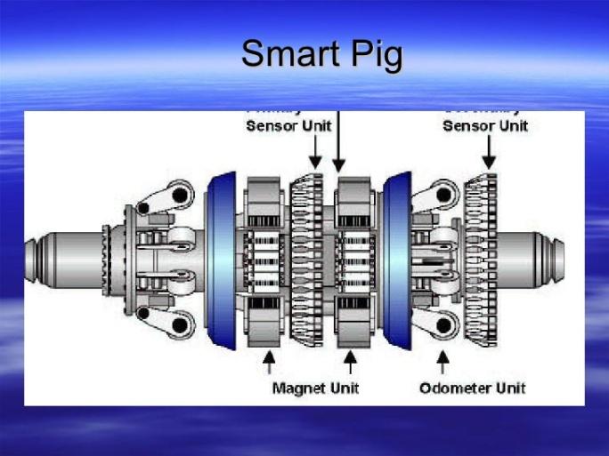
12 Electromagnetics (MagneticFluxLeakage Pigging) Acoustics (Sound Signatures)
")
13 Spray on CIPP Close Fitting HDPE Lining Systems Sliplining Pipe Bursting/Splitting/Reaming Panel Liners Spiral Wound Lining Spot/Point/Local Repairs Manhole Rehabilitation Sewer Lateral (Branch) Rehabilitation


14 4 144 dia. Pipes Non-Structural (host pipe needs to be structurally sound) Provides corrosion protection Improved hydraulics Cement Mortar Used in all pipes except plastic
15 Majority of spray on liners in sanitary sewers are for man-entry
16 (CIPP)

17 A flexible resin-impregnated tube is installed into an existing pipe, expanded out to fit the existing pipe and then cured in place to become a hard pipe. Components: Carrier Tube + Resin + Catalysts for Resin.

18 Pipe Type Structural Lining Pipe Size Same (less liner thickness) Pipe Life 50+ years Site Preparation Low disruption Replacement/Rehab Cost Low Social Impact - Minimum

19
20 Must be designed to withstand external loads. Can be designed as a stand alone pipe or less. North American design standard is ASTM F1216 Appendix X mm (6 ) to 2000 mm dia. (78 ) or larger. Suitable for round, oval or egg shaped sewers. Flow diversion/bypass required.

21 Basic Types of CIPP tube Non-reinforced most common for sewers Felt tube + Resin Reinforced less common for sewer but increasing use Reinforcement is in carrier tube, typically fiberglass. Can also be Carbon Fiber

22 Materials Polyester most common for sewers Vinylester less common for sewers Epoxy less common for sewers

23 Wet-Out is when the dry carrier tube is loaded with resin (impregnation) Wet-Out usually done at off-site facility Liners typically come to site in refrigerated trucks Some types of liner, such as UV Cure, do not require refrigeration
24 Four methods of curing are used for CIPP: Ambient Cure Cures by itself. Cure starts as soon as resin is mixed. Must be installed quickly. Not typically used for full length lining in sewers. Hot Water Cure Needs to raise liner temperature to start and complete cure. Heated water used to add energy.
 UV light provides the energy to the liner to start and complete the cure reaction")
25 Steam Cure (Steam is dominant) Needs to raise liner temperature to start and complete the Cure UV Cure (Ultra Violet Light) UV light provides the energy to the liner to start and complete the cure reaction

26 Inversion water or air pressure used to turn the resin filled tube inside out into and against the interior of the host pipe.

27 Pulled-in-Place resin filled tube is pulled into the host pipe with a cable and then air or water pressure is used to expand the liner to fit against the interior of the host pipe.

28 A fiberglass liner is usually pulled into the host pipe. A light train and CCTV is inserted in one end and pulled to the opposite end recording the precure condition of the liner. The light train is then pulled back through curing the liner, at a regulated speed, with the CCTV camera recording the actual curing of the liner.


29

30


31

32
33 Structural lining system typical sized 6 12 water mains capable to line up to 48 dia. Spans and seals leaking joints, pinholes, and fractures Services reinstated from inside the pipe no excavation Epoxy based resin system Installation lengths up to ft and able to negotiate bends (max. 45 )

34 Installation The lining length is governed by the diameter, restrictions, and appurtenances. The number of access pits are governed by the number of appurtenances (tees, valves, and hydrants)
35 CCTV Inspection & Plugging The services must be internally plugged before lining installation and opened after lining curing by a robot.


36 On-site wetout Off-site wetout

37 Inversion process similar to unrolling a sock

38

39 Reinstatement of Service Connections Services are opened from within the pipe using a robot and CCTV

40 Symmetrical Reduction and Fold and Form

41 Have been used since early 1980 s Uses a high density polyethylene liner 2 48 in diameter Section length average 2 3,000 but can be up to 5,000 Increased cleaning of the host pipe vs. sliplining

42 Polyethylene pipe is pushed through concentric rollers which reduce the diameter of the liner. Reduced diameter of the liner pipe allows it to be pulled through the host main. Liner is then pressurized with water at an ambient temperature to revert to its original size. Bends up to deg

43 Polyethylene pipe is pulled through a die that reduces the diameter of the liner. A constant tension must be maintained throughout the installation in order to keep the reduced diameter Once inserted the constant tension on the pipe is gradually removed allowing the pipe to revert back to its original diameter Bends up to deg


44 Transmission mains for diameters up to 48 Structural or non-structural lining PE pipe is folded, pulled in and re-rounded Long pulls (up to 3000 ft) possible in straight pipes Can negotiate bends up to 22 ½ deg.

45 PE Processing: Passed through a machine which forms it into a C shape. Straps are added to retain folded shape. Reversion: Pipe is filled with water and pressurized. Causing the retaining straps to break and returning pipe to original shape, (Close fit system) Reconnect

46
47 Sliplining is a pipe rehabilitation/renewal method that involves the insertion of a new smaller pipe inside an existing pipe by pulling or pushing the new pipe into place Two main types: Continuous Segments of a new pipe are joined to form one continuous liner before insertion into the existing pipe Segmental Short segments of a pipe are joined together at the insertion point into the existing pipe.

48 Pipe Type: New Pipe Size: Smaller than host pipe Structural Support: Partial or full Liner Material: HDPE, PVC, CSP, GRP, Composite, Steel and others Pipe Life: 50+ years Site Prep: Access Pits often required Social Impact: Moderate


49


50

51 Continuous slipliner pipes may require relaxing before steps are taken Gap between host pipe and slipliner pipe may be grout filled

52
. Replacement pipeline pulled in behind head.")
53 Pipe bursting/splitter head inserted into existing pipeline. Pipe is fractured or split. Fragments expanded in subsurface (through use of expander cone). Replacement pipeline pulled in behind head.
54 Pipes up to 36 diameter. Installation of new structurally independent replacement pipe pipe is typically HDPE or PVC. Relatively straight pulls up to 1,000 feet. o feet common for mainlines o feet common for laterals Burst: fractureable pipe such as cast iron, clay asbestos cement, concrete, etc. Split: ductile iron, steel, etc.

55 Site preparation: moderately disruptive Social Impact: moderate New Pipe Life: 50+ years depending on pipe type Pipe size: Can replace with same or up to 3 diameters larger

56 Upsizing existing pipeline up to 25% routine. Upsizing between 25% and 50% can be moderately difficult or challenging. Upsizing from 50% to 125% can be very challenging.

57

58 Mainline Pneumatic Systems Static Systems Lateral Small pneumatic or static portable systems

59 Horizontal Jack Hammer Constant Pressure Winch

60 Brute Force


61

62

63

64 Existing Pipe Type: VCP, ACP, Concrete, etc. Pipe Size: Same or upsize of 2 pipe diameters. Pipe Life: 50+ years. Site Preparation: Moderately Disruptive Social Impact: Moderate

65

66 Avoid Frac Out: Controlled reaming pressures Consistent soil conditions Experienced contractor
67
68 GRP (glass reinforced plastic) with cement filler. Grout filled annular gap. Full structural capacity for external loads. Custom shapes and sizes. WRc SRM type I and II designs. Type of annular gap grout dictated by design.


69 Panels can be custom made for most shapes.


70 Custom bend and size transitions can be made.


71 Panels transported within the sewer to the required location Next panel moved to the previously installed section and joined with the lap joint design Seal in joint creates watertight connection to prevent infiltration and grout leakage inside the panels

72 Excavate access pits Clean sewer and remove any obstructions Set up bypass system for sewer and service lateral flow Insert panels in the sewer Block panels to create space between the panels and the sewer Extend service laterals into the GRP panels Grout between the panels and the sewer
73 Insertion

74 Low flows can be accommodated during panel installation Full bypass required during grouting of annular space
75 Remove dirt and debris jetting, flushing. Remove protrusions hindering panel insertion. Remove tuberculation in iron and steel pipes. May need to remove/modify existing bends. Less cleaning and prep required than for other methods such as CIPP. Similar to sliplining requirements. Holes/openings in host pipe can lead to excessive grout loss into ground. Patching/repair of host pipe sometimes needed to limit grout escaping. Eliminate water in annulus gap during grouting.


76 Laterals and branch connections must be extended from the existing sewer wall to the liner. Connection extension must prevent grout from getting into the lateral/branch.


77
78 Panel lining is for non-pressure pipe applications o Sewers o Culverts o Other non-pressure pipelines Panel (thickness, properties) and grout (type, strength) selected to meet external load requirements Typically not suitable for pressure pipe applications

79


80 For Gravity Applications Continuous strips of plastic wound into pipe, typically through a manhole. Edges of the strips lock together to create a continuous spiral formed liner inside the host pipe. Strips have ribs providing stiffness to the product. o Some products use steel reinforcing to increase the structural strength of the product (resistance to external loading). Annular space between the line and the existing pipe typically filled with cementitious grout.
81 For use in man-entry and non man-entry pipes, typically larger than 16 diameter and up to 16. o Minimum diameter for some products is 36. Suitable for circular and non-circular pipe shapes. Can be designed to provide full structural support. o Not all products are fully structural. Line materials: PVC, Steel reinforced PVC, Steel reinforced HDPE.
. Inspect final product and reestablish flow.")
82 Setup bypass pumping to divert sewage flow as necessary. Clean pipe to remove debris and obstructions such as protruding laterals. Record location of all side connections (laterals). Insert plastic strips to form liner. Extend laterals through the liner. Grout the annular space (often in multiple lifts). Inspect final product and reestablish flow. Standards for spiral-wound PVC profile wall liners: ASTM F 1697 and 1698, as well as F 1735 and 1741.

83 Two Methods Available: Liner wound into the pipe by hand by manentry or

84 Liner insertion by machine at base of manhole. Machine can either be static or traversing.


85 Many products require filling the annular space with cementitious grout. To avoid deformation to the liner and floating: o The grout may require installation in multiple lifts and/or o An internal frame may be installed.

86 Lateral and branches need to be extended from the host pipe through the liner. The lateral extensions must prevent grout from entering the lateral.


87 Grouted in place unreinforced PVC for circular and non-circular sewers from 36 to 144.


88 Grouted in place reinforced interlocking PVC profile for circular or non-circular sewers from 18 to 16.

89 Close fitting unreinforced PVC for circular sewers from 6 to 30 Minimal or no-bypass required


90 Grouted in place close fitting reinforced PE for circular sewers from 16 to 120 The edges of the profile are welded together forming a continuous watertight liner.


91
92 Also called point, local or sectional repairs Repairs to short sections of defective pipe, joints or lateral connections Often used to address a structural defect or infiltration Cost effective compared to full length lining (depending on number of repairs required in a given length of water main or sewer)

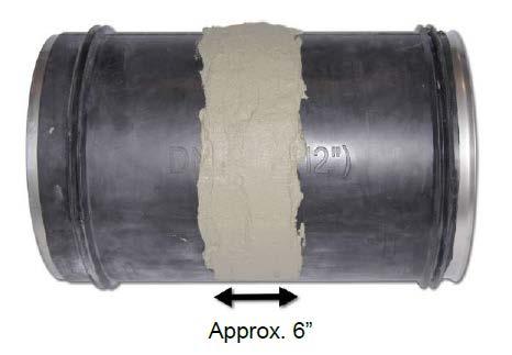
93 Seal provides a leak-proof joint repair on a structurally sound pipe. Existing pipe joint is bridged by the rubber seal allowing continued movement of the pipe joint. Withstands both internal and external pressures. Man entry required for installation.


94
95 Installation of cylindrical metal of PVC sleeve into the interior of a pipe at the defect location Sleeve is manufactured in a folded/collapsed state, inserted in place, then expanded to fit tightly against the host pipe Gaskets, chemical sealants, and other products used to seal the sleeve against the pipe wall Can resist external loads and stop infiltration in sewers


96

97 Larger diameter: PVC sleeves Round, tear drop, horse-shoe, and oval pipes
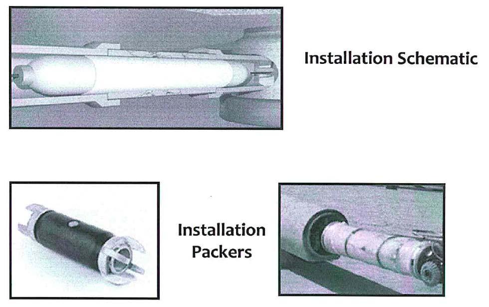
98 Cured-In-Place Pipe (CIPP) Spot Repair A short length of flexible resin-impregnated tube is installed into an existing sewer pipe, expanded out to fit the existing pipe, and then cure in place to become a hard pipe. Components: Carrier Tube + Catalysts for Resin Resin types: Polyesters, vinyl esters, and epoxies Size Ranges: Diameters 8 to 36 ; Lengths 3 to 6 (and longer) Shape: Circular, egg shape, oval (shaped with smooth curves)


99 Installation typically completed through manholes. Tube is saturated with resin, in the filed, wrapped around an inflation packer and winched through the existing pipeline to the defective section. Lateral can be opened after spot repair with robot cutter or man entry. The packer is then inflated and the resin is allowed to cure. Heater packers are used to speed up the cure time.

100
101

102 Can reduce or eliminate inflow and infiltration Inflatable packers isolate the section allowing controlled application of grout Variety of chemical grouts, chosen based on pipe materials, and surrounding soil conditions


103

104 Fiber Reinforced Polymer Prevents pipes from bursting, collapsing or further deteriorating Suited for emergency repairs Internal and external

105 Sheets made of carbon and glass reinforcing fibers combined with resin Applicable to large diameter pipe repair and strengthening Localized spot repairs

106 Spot Repairs for Non-Pressure Pipes o Sewers Culverts o Other non-pressure pipelines Spot Repairs for Pressure Pipes o Joint Seals o Specialized repairs using special products For non-pressure pipe applications, spot repair performance matched to external load requirements For pressure pipes, spot repair performance matched to internal pressure requirements including applicable vacuum. External load may need to be considered.

107

108

109 Manholes Are an important part of a wastewater collection system. Provide access to pipelines for: o Maintenance o Inspection o Renovation Are subject to a variety of degradation issues.
110 There are many technologies for the renovation of manholes. They include: Products for corrosion protection. o Coatings and linings for leakage control. o Products for structural enhancement. o Specialty products installed to primarily stop leakage. NOTE: To achieve proper results, most manhole coatings and linings are installed by certified or trained applicators with an extensive application history.

 These two")
111 There are several MH rehabilitation products on the market today. Two types of products: o Performance Based on Bond o Performance Based on Wall (ASTM F1216 for circular) These two mechanisms of performance can be classified as Bonded or Non-Bonded
112 Surface prep: one of the most important factors in immediate and long-term MH rehab success o Clean oils, greases, scale, and deposits o Stop water infiltration o Allow substrate to dry Obtain roughness profile (in some cases) Standards: National Association of Corrosion Engineers (NACE) and Society of Protective Coatings (SSPC)
113 Long established history with recent improvements in fast setting high strength corrosion resistant mortars. Material either spray or trowel applied. ¼ to 2 thickness depending on degree of deterioration. Done in multiple passes.
114 Additives such as silica sand, polypropylene fibers, silica fume, and calcium aluminate provide coatings with: Strength Rapid cure Bond strength to existing concrete Abrasion resistance Corrosion resistance

115 Can also be used as repair material with or without polyurethane or epoxy top coats for: o Structural issues o Infiltration o Holes and cracks

116 Typically spray applied. Many variations from elastomeric to rigid formulations. Generally, 100% solids used for underground coatings. Quick cure times. Rapid build. High tensile strength and excellent elongation properties.

117 Structural enhancement Elastomeric versions able to withstand environmental factors o Freeze/thaw cycling o Vibration o Seismic activities o Abrasion Chemical resistance o Hydrogen sulfide o Sulfuric acid o Chlorine o Road salts
118 Typically either spray or trowel applied with many variations available. Generally, only 100% solids used for underground coating. Adheres to moist or damp substrates. High build formulas available. Excellent chemical resistance and long-term physical properties.
119 Seamless thick wall concrete liner. Use of segmented, stackable, and removable forms. Usually poured in lifts and can etend from bench to frame. Use of fiber reinforcement can probide higher strength.
120 Extensive installation history. Excellent chemical resistance. Both PVC and HPDE products avaiable. Typically used with cementitious or polymer mastic basecoats.
121 Used for structural renewal. Have excellent chemical resistance and strong, long-term physical properties. Primarily use epoxy resins. Fiberglass or polyester knit tubes.
 Cure liner (steam,")
122 1) Prepare Manhole 2) Insert epoxy resin saturated uncured liner 3) Inflate bladder to compress liner against manhole 4) Cure liner (steam, ambient)

123 40+ year history Stops flowing water o o o Seals cracks Consolidates surrounding soil Fills voids 5 second to several hour gel time Hydrophilic and hydrophobic varieties o o Foam Gel Can be used together

124
125 There are generally two varieties of soft liner lateral technologies. o Lateral and connection o Lateral only Other technologies include Pipe Bursting and Slip Lining.


126 Full circumferential liner in mainline One piece with the mainline and lateral liner 6-24 mains 3-8 laterals

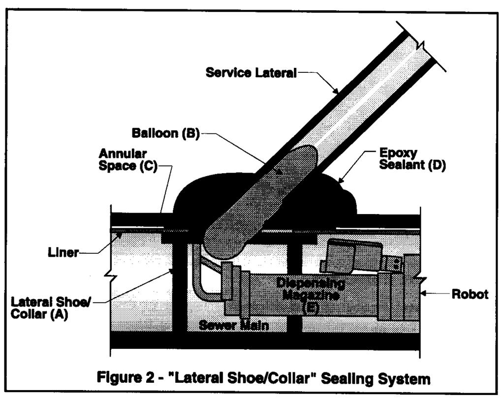
127 Section of lateral lined and a brim placed around the connection T or Y connections 6 21 mainlines 3 lateral extension
128 Seals lateral connection and a few feet up that lateral Eliminates infiltration no structural enhancement
129 Robotics/Epoxy
130

131