RUUKKI FAÇADE SYSTEMS
|
|
|
- Eunice Golden
- 5 years ago
- Views:
Transcription


1 RUUKKI FAÇADE SYSTEMS
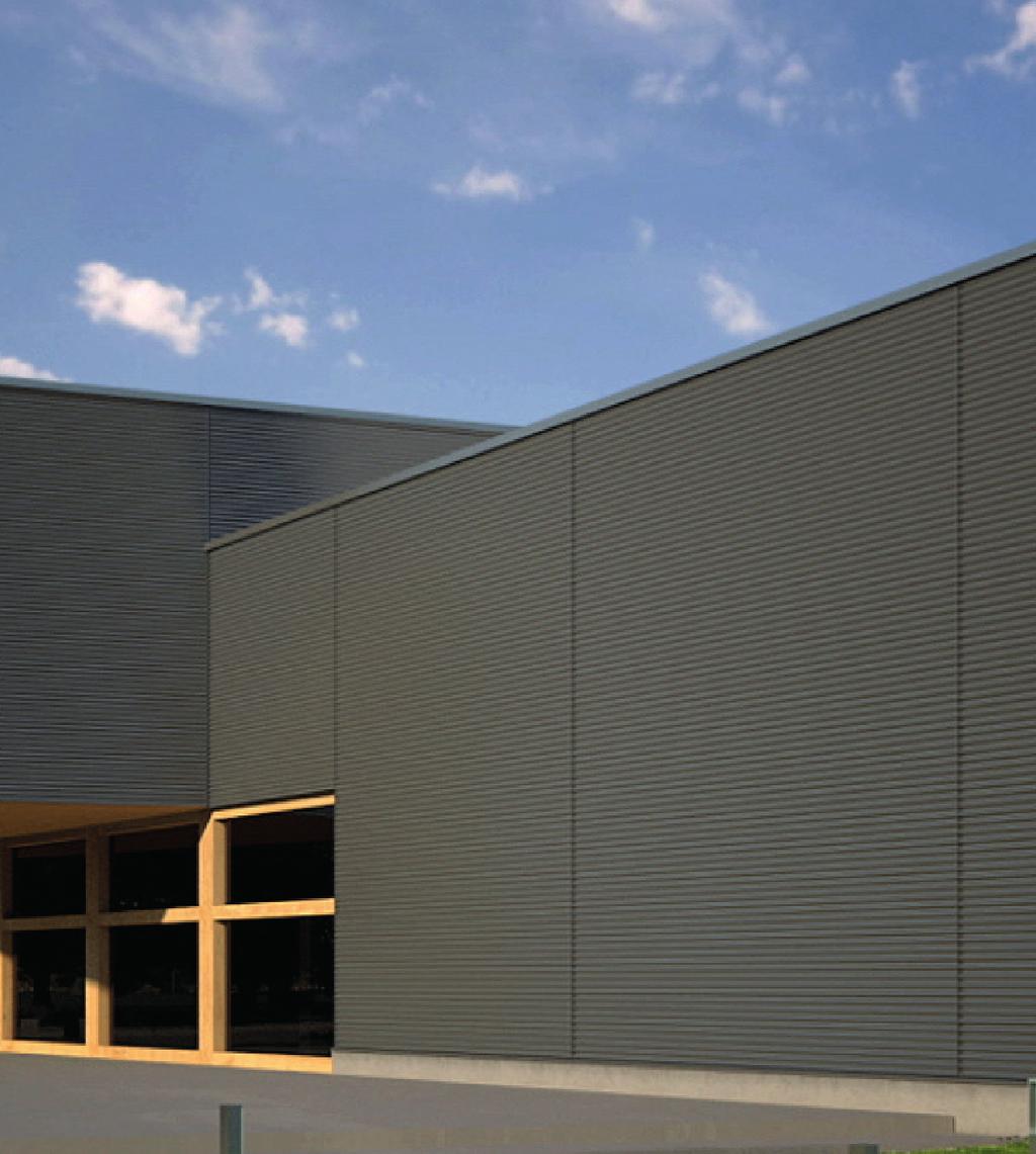
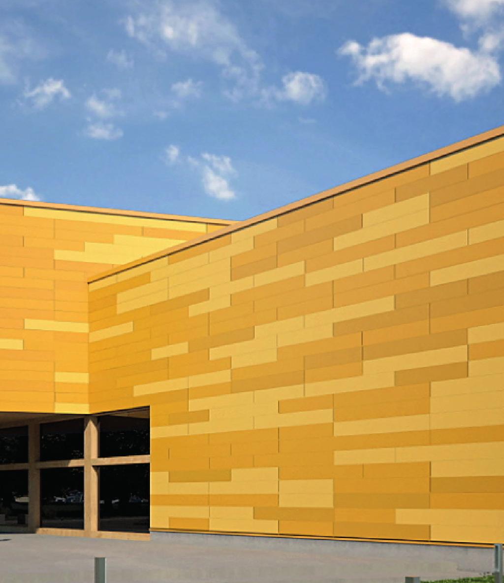
2 1. General Ruukki Forma is a complete façade system in which Ruukki energy panels form an energy efficient base structure and Ruukki cladding products finalize the visual looks for the building façade. Ruukki energy panels are steel faced insulated sandwich panels with excellent air tightness for high energy efficiency. With Ruukki energy panels the building can be quickly covered from weather. Panels are available with different technical properties and insulation materials for various needs. Detailed and up to date energy panel properties are available from Ruukki cladding products offer a wide range of shapes, materials and colours for the visual design of the façade. Ruukki cladding product portfolio includes: Liberta cassettes Cladding lamellas Design profiles. Detailed and up to date information about Ruukki cladding products is available from Ruukki Forma includes all needed accessories such as fixings, sealants, studs and flashings. Ruukki Forma comes with full design support as well as Ruukki energy simulation service for optimized energy efficiency. This type of system and build technique offers the following key advantages: 1. Rapid watertight envelope. 2. Consolidation of up to x5 components in one (compared to other traditional forms of construction). 3. Enables concurrency of tasks both inside and outside the building thus shortening lead time. 4. Fixture of external rainscreen is removed from the programme critical path. 5. Desensitises cost plans to fluctuating labour costs. 6. Enhanced air tightness. 7. Reduced risk of missing/incorrectly installed components. All factors above can have a positive effect in terms of decreasing build time, increasing cost certainty and reducing risk. 2. Design principles Designing of Ruukki Forma can be divided into 2 main phases: 1. Design of base structure (Ruukki energy panel system) 2. Design of cladding & cladding support system Design of base structure (Ruukki energy panel system) Base structure is designed using special Ruukki Forma construction details. Panels can be installed either horizontally or vertically. Main phases for base structure design are: a. Selecting suitable panel type based on required technical properties (U-value, fire etc.). Product properties can be found from b. Checking panel strength against given loads and spans by using Ruukki s load/span tables or dimensionin program TrayPan. c. Utilizing Ruukki Forma principle details in designing of project specific details. Details are available from d. Calculating the needed amount of panel fasteners (see paragraph 3). Design of cladding & cladding support system Cladding products are always fixed to base structure via Ruukki s support studs. More detailed instructions for cladding system design are given in paragraphs Ruukki forma design instructions
3 PANEL PASTENER SUPPORT STUDS c/c SUPPORT STUD FASTENERS c/c 250 NOTE: If support studs are running perpendicular to panels (e.g. panels installed horizontally between columns and support studs vertically), the utilization rate for bending moment against wind pressure has to be limited to 85%. This can be checked with Ruukki s dimensioning program (TrayPan). Fire design Reaction to fire classification for Ruukki Forma with steel based external face is the same as for it s base structure (Ruukki energy panel system). The fire resistance classification for Ruukki Forma against the fire from inside the building is the same as for it s base structure (Ruukki energy panel system). In case of fire resistance requirements against the fire from outside the building, please contact Ruukki s technical support. 3. Designing fastenings The fastenings of Ruukki Forma have been pre-designed to make design work easier. It is important that only fasteners supplied by Ruukki are used to ensure that the fastening solution works as planned. Fastening support studs to base structure (Ruukki energy panels) Support studs are fixed to outer skin of the panel by using overlap screws (Ruukki code Screw S1H48023L02A4 ) at 250 mm centers from both flanges. The edge distance (distance from screw to panel edge) has to be 100 mm. If support studs are running perpendicular to panels (e.g. panels are installed horizontally and support studs vertically), support studs are located at maximum of mm centers, depending on cladding type (see paragraphs 4-6). Full length ( panel module width x 2) support studs must be used to distribute the loads between adjacent panels. If support studs are running to same direction as panels (e.g. both panels and support studs are installed vertically), the maximum stud center is 600 mm. Support studs must reach the panel ends. If base structure is not flat, i.e. panels are not forming an even surface (e.g. due to tolerances in load bearing frames) to cladding material, adjustable Ruukki studs have to be used. Adjustable Ruukki studs can accommodate up to 30 mm tolerances. Ruukki forma design instructions 3
4 Following values have been used for calculating the above mentioned stud and fixing centers: Panel facing thickness: 0.5 mm Characteristic tensile strength: 0.6kN/screw Characteristic shear strength: 0.6kN/screw Maximum wind pressure load (un-factored): 1.4kN/m 2 Maximum wind suction load (un-factored): 2.0kN/m 2 Maximum cladding system weight: 30kg/m 2 Material safety factors for fastenings: 1.33 Load safety factors: 1.35 (own weight); 1.5 (wind load) Compression strength of the base structure: 0.053Mpa Load combinations: - Wind pressure + Cladding weight - Wind suction + Cladding weight - Wind pressure + Wind suction (interaction) Fastening base structure (Ruukki energy panels) to load bearing frames Panels are fixed to load bearing frames using penetrating panel fasteners. Fastener type is selected based on load bearing frame material (steel, wood or concrete) and panel thickness. Please contact Ruukki for recommended fastening type. The edge distance for the fastening (distance from fastening to panel edge) has to be 30 mm. When calculating the needed amount of panel screws, following loads need to be considered: Wind suction load (pull-through strength): The needed amount of fasteners can be easily calculated by using Ruukki s dimensionin program TrayPan. Alternatively, fasteners can be calculated manually by using tensile strength values as given in table 1 below. Self weight (shear strength): The needed amount of fasteners can be calculated manually by using shear strength values as given in table 1 below and the Ruukki Forma weight. The system weight consist of: Base structure weight: Check the weight of chosen Ruukki energy panel type (depends on panel type and thickness). Cladding & cladding support material weight: 20kg/m 2 (cladding + support studs) can be used for all cladding options in Ruukki Forma. Whichever calculation from the above (wind suction and self weight) results bigger amount of screws, is then finally the needed amount of screws. Table 1. Panel fastener strengths (edge distance 30 mm). Fastener type Panel fastener, washer Ø 19 mm Shear strength, characteristic (N) Shear strength, allowed load (N) 1 Tensile strength, characteristic (N) (1299) (720) , , 4 Tensile strength, allowed load (N) 2 1. Safety factors for shear strength: Material 1.33; Load (self weight) Safety factors for tensile strength: Material 1.33; Load (wind) Valid for Ruukki energy panel with MW (mineral wool) core. 4. Valid for Ruukki energy panel with PIR or PU core. 4. Ruukki Forma with Liberta cassettes The wall structure in Ruukki Forma with Liberta cassettes is as follows: 1. Base structure: Ruukki energy panel system fixed to load bearing frames 2. Support studs fixed to outer skin of base structure 3. Libertas fixed to support studs 4 Ruukki forma design instructions


5 RUUKKI ENERGY PANEL SUPPORT STUD c/c ATTACHMENT OF LIBERTAS ACCORDING TO INSTALLATION INSTRUCTIONS Design of base structure (Ruukki energy panel system) See paragraph 2 above. Moreover, to ensure flat visual appearance for the Liberta, the energy panel deflections should be limited as follows: Liberta length 0 1 m: L/100 Liberta length 1 2 m: L/200 Liberta length 2 3 m: L/300 Design of cladding & cladding support system Before ordering Libertas project-specific plans should be made, considering the background structures, Liberta frame structures, Liberta installation direction, joint width, ventilation, thermal expansion and gaps as well as flashings and fastenings. The plans should be made by a structural design company familiar with facade planning or the structure planner of the building project. Liberta installation drawings are made based on the facade drawings. The Libertas are identified with unique ID numbers. Liberta dimensions must match the architect`s plan, which is complemented by detailed dimensions of the horizontal and vertical Liberta joints as well as details of any corner, window and door connections. Based on these plans the installer can report the Liberta dimensions as the work progresses. At the same time the location and number of the Liberta substructure (support studs) should be specified. These are determined based on Liberta dimensions. Dimensioning The width and height of the Libertas (A- and B-dimensions) are measured from the center of the joint to the center of the joint. The depth (C) is measured from the top of the support stud to the outer surface of the Liberta and the joint widths (Dh and Dv) as the widths of the visible joints. The minimum and recommended maximum Liberta sizes are specified in separate Liberta size charts. Liberta joints The outward turned flanges form the base of the vertical joint between the cassettes Liberta original 102 and original 102Grande. In cassette Liberta elegant 500 and elegant 500Grande, the support stud is used as the joint base. In all Libertas the base of the horizontal joint between the Libertas consists of the turned Liberta flanges. Fastening holes The fastening holes are punched during Liberta manufacturing. The holes are round, with diameter 7 mm in Liberta Liberta original 102, or oval, 5 x 10 mm in size in casssettes Liberta original 102Grande, elegant 500 and elegant 500Grande. Standard fastening holes are made at the corners of the Liberta, 15 mm from the Liberta end. Additional holes are made automatically or according to customer specifications. If the customer does not specify the positions of the additional holes, the holes are always made automatically as described below. The positions of the required additional holes depend on the dimensions of the Liberta. The positions of the holes are expressed in the following Ruukki forma design instructions 5
6 format:a-dimension (B-dimension) / 2; A-dimension (B-dimension) / 3, etc. where A and B are dimensions of the Liberta sides and the divisor is a number indicating the number of equal-size parts the side should be divided into. The fastening holes are punched in B direction only in casssettes Liberta original 102 and original 102Grande. Standard fastening holes: A-dimension (B-dimension) 700 mm; fastening at the Liberta corners. A-dimension (B-dimension) mm / 2; fastening at the Liberta corners and in the middle. A-dimension (B-dimension) mm / 3; fastening at the Liberta corners and in the middle with two equally spaced fasteners. A-dimension (B-dimension) mm / 4; fastening at the Liberta corners and in the middle with three equally spaced fastener. A-dimension (B-dimension) mm / 5; fastening at the Liberta corners and in the middle with four equally spaced fastener (these dimensions apply to cassettes Liberta original 102Grande and elegant 500Grande only). Support studs The Libertas are fastened to support studs by self-drilling screws. When the Libertas are over 700 mm wide, additional center support studs are required. Moreover, if the support studs are fixed parallel to panel length, the maximum c/c for studs is 600 mm and the stud ends have to reach the panel end. Levelness of the substructure for the entire width of a Liberta is extremely important, so that fastening causes no deformation of the Liberta surface. In cassettes Liberta original 102 and original 102Grande, all the studs can be galvanized. In cassettes Liberta elegant 500 and elegant 500Grande, the studs at the vertical joints are visible and should be the colour of the Liberta (the additional center studs by the Libertas can be galvanized). NOTE: If support studs are running perpendicular to panels (e.g. panels installed horizontally between columns and support studs vertically), the utilization rate for bending moment against wind pressure has to be limited to 85%. This can be checked with Ruukki s dimensioning program (TrayPan). Support studs are fixed to outer skin of the base structure from both flanges with overlap screws ( Screw S1H48023L02A4 ) c/c 250 mm. Studs with only one flange (e.g. CA1RS1) are fixed c/c 125 mm. If base structure flatness can t be ensured, i.e. panels are not forming even surface (e.g. due to tolerances in load bearing frames) to cladding material, adjustable Ruukki studs have to be used. Adjustable Ruukki studs can accommodate up to 30 mm tolerances. Starting fillets In Libertas elegant 500 and elegant 500Grande separate starting fillet is needed (Starting fillet CA1SF2). Length of the starting fillet is determined as follows: Liberta A-dimension - width of one vertical joint between the Libertas (Dv) - 5 mm. The starting fillet is only visible from directly below. Special Libertas Libertas can be used for manufacturing various kinds of special cassettes for a wide range of uses. When using special Libertas, also note the general size recommendations of the Libertas. More detailed dimension regulations and the minimum and maximum dimensions that apply for special Libertas can be found on the dimensional drawings for the Libertas. Corner Libertas Corner Libertas can be made to extend around the external corner of the building. In addition to normal fastening holes in the Liberta is automatically included additional fastening holes on both sides at a 100 mm distance from the corner unless the customer requires otherwise. A single Liberta for the internal corner of a building cannot be manufactured two separate Libertas and a flashing must be used. Pitched Libertas Libertas with a pitched upper edge can be manufactured for the eaves of a building, for example. The lower edge of the Liberta or a vertical edge can also be pitched. Any holes are not made on the pitched edge. It is generally recommended for only one edge of the Liberta to be pitched. U-Libertas So-called U-Libertas (with two external corners) can be manufactured for lining pillars, for example, in building. In addition to normal fastening holes in the Liberta is automatically included additional fastening holes on both sides at a 100 mm distance from the corners unless the customer requires otherwise. The possibility to produce other special Libertas than those mentioned here must be determined case-specifically. 6 Ruukki forma design instructions

7 Ventilation There must be an adequate ventilation space (min. 20 mm) between the Liberta and the windshield, enabling an unobstructed air change. It must also be ensured that there are gaps in the upper and lower edge of the wall structure to ensure free air change. The lower edge of the Libertas has ventilation holes, through which the water that has entered the structure through the joints or is caused by condensation can be removed. The ventilation holes are oval, of 5 x 15 mm in size. The holes are prepared as described in the fastening hole instruction above, independent of the customer-specified fastening hole positions. The outermost holes are placed 60 mm from the Liberta ends. Facade flashings The number of the flashings in a Liberta facade can be decreased significantly through good planning, as the Libertas can be ordered to the exact shape and dimensions. Typical applications include the corners of the building, such as corner Libertas, window frames, etc. Flashings are typically designed to be covered by the Libertas to improve the esthetic quality of the facade. When planning the flashings the mounting method and shape of the basic Liberta must be considered. Note. When the flashings are powder coated, notice that the flashings must be designed and bent before coating. Flashings shall be coated at the same time with the Libertas to avoid variance in colour appearance. Other In case of Libertas made of Cor-Ten, please contact Ruukki for more detailed instructions. 5. Ruukki Forma with Cladding lamellas The wall structure in Ruukki Forma with Cladding lamellas is as follows: 1. Base structure: Ruukki energy panel system fixed to load bearing frames 2. Support studs fixed to outer skin of base structure 3. Cladding lamellas fixed to support studs RUUKKI ENERGY PANEL SUPPORT STUD c/c ATTACHMENT OF LAMELLAS ACCORDING TO LAMELLA INSTALLATION INSTRUCTIONS Design of base structure (Ruukki energy panel system) See paragraph 2 above. Moreover, to ensure flat visual appearance for the lamella, the energy panel deflections should be limited as follows: Lamella length 0 1 m: L/100 Lamella length 1 2 m: L/200 Lamella length 2 3 m: L/300 Design of base structure (Ruukki energy panel system) See paragraph 2 above. Moreover, to ensure flat visual appearance for the lamella, the energy panel deflections should be limited as follows: Lamella length 0 1 m: L/100 Lamella length 1 2 m: L/200 Lamella length 2 3 m: L/300 Ruukki forma design instructions 7
8 Design of cladding & cladding support system Before ordering lamellas project-specific plans should be made, considering the background structures, lamella frame structures, lamella installation direction, ventilation, thermal expansion and gaps as well as flashings and fastenings. The plans should be made by a structural design company familiar with facade planning or the structure planner of the building project. Lamella installation drawings are made based on the facade drawings. The lamellas are identified with unique ID numbers. Lamella dimensions must match the architect s plan, which is complemented by detailed dimensions of the lamella joints as well as details of any corner, window and door connections. Based on these plans the installer can report the lamella dimensions as the work progresses. At the same time the location and number of the support studs should be specified. These are determined based on lamella dimensions. Dimensioning The lamella width is always expressed as the manufacturing width excluding joints, the height as the effective height and the depth as the distance from the support stud surface to the exterior surface of the lamella. The exception to the rule is Lamella vertical 70, where the width is expressed using the manufacturing height and the height using the effective width (this lamella is for vertical installation only). Lamella joints The vertical lamella joints are usually left open and covered with vertical joint flashings. Depending on the lamella type, flashings can be installed either on top of the lamellas or under the lamellas. Vertical joints can also be done using lamella shaped joint pieces, which are installed under the lamella ends (not in Lamellas groove 10, 20 and 30). Note. There must be a gap of 4-5 mm between the lamella ends. Lamella vertical 70 is an exception as it already has a standard vertical joint (5 mm). The horizontal joints are distinct for each lamella type, excluding Lamella vertical 70, where sill flashing is used in horizontal joint. Fastening holes The fastening holes are punched during lamella manufacturing for Lamellas sharp 40 and 45, lap 60, vertical 70 and straight 100. The holes are oval, 5 x 10 mm in size. Standard fastening holes are made at the corners of the lamella, 15 mm from the lamella end. Additional holes are made automatically or according to customer specifications. If the customer does not specify the positions of the additional holes, the holes are always made automatically as described below. The positions of the required additional holes depend on the width of the lamella. The positions of the holes are expressed in the following format: Lamella width / 2; lamella width / 3, etc. where the divisor is a number indicating the number of equal-size parts the width should be divided into. Standard fastening holes: Lamella width 750 mm; fastening at the lamella corners. Lamella width mm / 2; fastening at the lamella corners and in the middle. Lamella width mm / 3; fastening at the lamella corners and in the middle with two equally spaced fasteners. Lamella width mm / 4; fastening at the lamella corners and in the middle with three equally spaced fastener. Support studs The lamellas are fastened to support studs by self-drilling screws. When the lamellas are over 750 mm wide, additional center support studs are required. Moreover, if the support studs are fixed parallel to panel length, the maximum c/c for studs is 600 mm and the stud ends have to reach the panel end. Levelness of the substructure for the entire width of a lamella is extremely important, so that fastening causes no deformation of the lamella surface. All support studs used in lamella systems can be galvanized as they do not remain visible. NOTE: If support studs are running perpendicular to panels (e.g. panels installed horizontally between columns and support studs vertically), the utilization rate for bending moment against wind pressure has to be limited to 85%. This can be checked with Ruukki s dimensioning program (TrayPan). Support studs are fixed to outer skin of the base structure from both flanges with overlap screws ( Screw S1H48023L02A4 ) c/c 250 mm. Studs with only one flange (e.g. CA1RS1) are fixed c/c 125 mm. If base structure flatness can t be ensured, i.e. panels are not forming even surface (e.g. due to tolerances in load bearing frames) to cladding material, adjustable Ruukki studs have to be used. Adjustable Ruukki studs can accommodate up to 30 mm tolerances. 8 Ruukki forma design instructions

9 Starting fillets In Lamellas groove 10 and 20, sharp 45, lap 60, and straight 100 a separate starting fillet is needed. Length (width) of the starting fillet is same than the width of the lamella. The starting fillet is visible in Lamellas groove 10 and 20. In Lamellas sharp 45, lap 60 and straight 100 the starting fillet is only visible from directly below. Special lamellas Corner lamellas Two separate lamellas slanted at a 45 degree angle can be combined to make a corner lamella, which can be used for the external and internal corners of the building. These external and internal turns can be done with Lamellas groove 10, 20 and 30, sharp 40 and 45, lap 60 and straight 100. The maximum width for the corner lamellas is mm. The corners are measured from the outermost point on the lamella. Corner lamellas are used with flashings designed for that purpose. The possibility to produce other special lamellas than those mentioned here must be determined case-specifically. Ventilation There must be an adequate ventilation space (min. 20 mm) between the lamella and the windshield, enabling an unobstructed air change. It must also be ensured that there are gaps in the upper and lower edge of the wall structure to ensure free air change. The lower edge of the lamellas has ventilation holes (not in Lamellas groove 10, 20 and 30 and vertical 70), through which the water that has entered the structure through the joints or is caused by condensation can be removed. The ventilation holes are oval, 5 x 15 mm in size. The holes are prepared as described in the fastening hole instruction above, independent of the customer-specified fastening hole positions. The outermost holes are placed 60 mm from the lamella ends. Facade flashings The number of the flashings in a lamella facade can be decreased significantly through good planning. Typical applications include the corners of the building, window frames, etc. Flashings are typically designed to be covered by the lamellas to improve the esthetic quality of the facade. When planning the flashings the mounting method and shape of the basic lamella must be considered. Note. When the flashings are powder coated, notice that the flashings must be designed and bent before coating. Flashings shall be coated at the same time with the lamellas to avoid variance in colour appearance. Other In case of lamellas made of Cor-Ten, please contact Ruukki for more detailed instructions. 6. Ruukki Forma with Design profiles The wall structure in Ruukki Forma with Design profiles is as follows: 1. Base structure: Ruukki energy panel system fixed to load bearing frames 2. Support studs fixed to outer skin of base structure 3. Design profiles fixed to support studs RUUKKI ENERGY PANEL SUPPORT STUD c/c ATTACHMENT OF LAMELLAS ACCORDING TO LAMELLA INSTALLATION INSTRUCTIONS Ruukki forma design instructions 9
10 Design of base structure (Ruukki energy panel system) See paragraph 2 above. The energy panel deflection has to be limited to L/100. Design of cladding & cladding support system Before ordering Design profiles project-specific plans should be made, considering the background structures, Design profile frame structures, Design profile installation direction, ventilation, thermal expansion and gaps as well as flashings and fastenings. The plans should be made by a structural design company familiar with facade planning or the structure planner of the building project. Design profile installation drawings are made based on the facade drawings. The Design profiles are identified with unique ID numbers. Design profile dimensions must match the architect s plan, which is complemented by detailed dimensions of the Design profile joints as well as details of any corner, window and door connections. Based on these plans the installer can report the Design profile dimensions as the work progresses. At the same time the location and number of support studs should be specified. These are determined based on Design profile dimensions. Dimensioning The Design profile width is always expressed as the manufacturing width excluding joints, the height as the effective height and the depth as the distance from the support stud surface to the exterior surface of the Design profile. Design profile joints The vertical Design profile joints are usually left open and covered with vertical joint flashings. Depending on the Design profile type, flashings can be installed either on top of the Design profiles or under the Design profiles. Support studs The lamellas are fastened to support studs by self-drilling screws. When the Design profiles are over 900 mm wide, additional center support studs are required. Moreover, if the support studs are fixed parallel to panel length, the maximum c/c for studs is 600 mm and the stud ends have to reach the panel end. Levelness of the substructure for the entire width of a Design profile is extremely important, so that fastening causes no deformation of the Design profile surface. All support studs used in Design profile systems can be galvanized as they do not remain visible. NOTE: If support studs are running perpendicular to panels (e.g. panels installed horizontally between columns and support studs vertically), the utilization rate for bending moment against wind pressure has to be limited to 85%. This can be checked with Ruukki s dimensioning program (TrayPan). Support studs are fixed to outer skin of the base structure from both flanges with overlap screws ( Screw S1H48023L02A4 ) c/c 250 mm. Studs with only one flange (e.g. CA1RS1) are fixed c/c 125 mm. If base structure flatness can t be ensured, i.e. panels are not forming even surface (e.g. due to tolerances in load bearing frames) to cladding material, adjustable Ruukki studs have to be used. Adjustable Ruukki studs can accommodate up to 30 mm tolerances. Ventilation There must be an adequate ventilation space (min. 20 mm) between the Design profile and the windshield, enabling an unobstructed air change. It must also be ensured that there are gaps in the upper and lower edge of the wall structure to ensure free air change. Facade flashings The number of the flashings in a Design profile facade can be decreased significantly through good planning. Typical applications include the corners of the building, window frames, etc. Flashings are typically designed to be covered by the Design profiles to improve the esthetic quality of the facade. When planning the flashings the mounting method and shape of the basic Design profile must be considered. Note. When the flashings are powder coated, notice that the flashings must be designed and bent before coating. Flashings shall be coated at the same time with the Design profiles to avoid variance in colour appearance. Other In case of Design profiles made of Cor-Ten, please contact Ruukki for more detailed instructions. 10 Ruukki forma design instructions
11 7. Calculation example Ruukki Forma with Design profile Design Tokyo S18 Orientation: Horizontal Building column centers: 6000 mm U-value requirement: 0.17W/m 2 K Fire resistance: EI60 Reaction to fire: A2-s1, d0 Design of base structure (Ruukki energy panel system) Based on the U-value and fire resistance requirements, SPA230E ENERGY is chosen as a base structure. This is a 230 mm thick MW (mineral wool) core panel and it will be installed horizontally, i.e. spanning between columns at 6000 mm centers. Wind loads (un-factored) as given by the structural engineer are as follows: Mid areas: ±0.6kN/m 2 Corner areas: +0.6kN/m 2 (wind pressure) / -0.9kN/m 2 (wind suction) Width of corner area: 6000 mm According to Ruukki s panel dimensioning program TrayPan, the SPA230E ENERGY can easily withstand the above given wind loads. Design of cladding & cladding support system Design Tokyo S18 is fixed to base structure via Ruukki s support studs. As the Design Tokyo S18 will be installed horizontally (just like the base structure), support studs must be installed vertically. Therefore, according to rules, bending strength utilization rate against wind pressure must be limited to 85%. According to TrayPan, the utilization rate in this case is only appr. 37%, so the strength of the base structure is OK. Design of fastenings The fastening system for Ruukki Forma has been pre-designed. Screws supplied by Ruukki are used to ensure that the fastening solution works as planned. Fastening support studs to base structure (Ruukki energy panels) According to instructions in paragraph 3, support studs are fixed to external face of the panel by using overlap screws (Ruukki code Screw S1H48023L02A4) at 250 mm centers from both flanges. The edge distance (distance from screw to panel edge) is designed to be minimum of 100 mm. Support studs are designed to 900 mm centers in accordance with the rules in paragraph 6. Fastening base structure (Ruukki energy panels) to load bearing frames Panels are fixed to load bearing frames using penetrating panel fasteners. Fastener type SCREW S3H55275D14S9B 100 is selected according to instructions from Ruukki. This screw type is self-drilling stainless steel screw for steel frame with thickness 4-14 mm. Wind suction load (pull-through strength): According to TrayPan, the needed amount of screws in corner area is 3 no per panel end. In mid areas 2 no per panel end is enough. Manual calculation: (wind suction load x panel module width x span/2) /allowed tensile strength of fastener. Mid area: (-0.6kN/m 2 x 1.2 m x 6m/2)/1.05kN = 2 no 2 fasteners / panel end Corner area: (-0.9kN/m 2 x 1.2 m x 6m/2)/1.05kN = 3 no 3 fasteners / panel end Self weight (shear strength): The needed amount of screws is calculated manually based on system weight: Base structure weight: The weight of SPA230E ENERGY is 30.4kg/m 2 ( Cladding + support stud weight: 20kg/m 2 (according to paragraph 3) Total wall weight: 50.4kg/m 2 Against the wind suction loads minimum of 2 no of fixings per panel end (mid areas) are needed. This equals 4 fixings per 7.2 m 2 are of wall. According to table 1, the allowed shear strength for one screw is 900N 4 no of screws 3.6kN = 360 kg. The total weight of 7.2 m 2 wall area is 360 kg. In this case 4 no of screws is enough. Finally, wind suction load results higher amount of needed screws: Corner areas: 3 no per panel end. Mid areas: 2 no per panel end. Ruukki forma design instructions 11
12 Ruukki provides its customers with energy-efficient steel solutions for better living, working and moving. CUK002/EN/ /PI This publication is accurate to the best of our knowledge and understanding. Although every effort has been made to ensure accuracy, the company does not assume any responsibility for any errors or omissions, or any direct, indirect or consequential damage caused by incorrect application of the information. We reserve the right to make changes. Always use original standards for accurate comparison. Ruukki UK Ltd, Ruukki Construction, Suite 6, Cranmore Place, Cranmore Business Park, Solihull, West Midlands, B90 4RZ. +44 (0) , Copyright 2014 Rautaruukki Corporation. All rights reserved. Ruukki, Rautaruukki, Living. Working. Moving. and Ruukki s product names are trademarks or registered trademarks of Rautaruukki Corporation.