Structural Technical Report 1 Structural Concepts/ Structural Existing Conditions Report
|
|
|
- Aubrey Ferguson
- 5 years ago
- Views:
Transcription
1 Kelly M. Sadusky The Food Science Building Oct. 6, 2004 Professor Parfitt University Park, PA Structural Option Executive Summery: Structural Technical Report 1 Structural Concepts/ Structural Existing Conditions Report The following report contains: 1. Applicable Building Codes 2. Summary of Structural System 3. Load Summary 4. Typical Bay Spot Check 5. Appendix The Food Science Building is to be built according to the International Building Code, 2000 edition. Steel design was according to AISC and building materials were according to ASTM standards. The building can be thought of as two separate structures. The West end of the building is an L shaped structure. Its framing is slightly different from that of the East end which is a simple box. Because of the different framing patterns, the two sections will be analyzed separately. The lateral system of the building is moment frames in both directions. It is composed of composite beams and composite floor decks. The third level framing plan contains 6 double Tee s which span over the foot of the L shape. The framing is partially restrained and semi rigid. My spot check for a typical beam came out to be exactly what the designers have found.
2 1. Applicable Building Codes: Loading was determined by the International Building Code 2000 Ed. o Minimum snow load of 40psf per IBC Code Local Amendment o Structural Steel design, detailing, and fabrication governed by AISC o Material properties confirm to ASTM standards o Reinforced concrete design governed by ACI and the CSRI Manual of Standard Practice. o Concrete masonry governed by ASTM C90 2. Summary of Structural System: Building Footprint- The building can be though of as two separate buildings, an L-shaped building (the West end) and a box like building (the East end.) The total gross square feet is 133,000. Floor to floor height Varies between each level, 16-0 basement to first and first to second, 15-4 second to third, 15-4 third to forth, 15-6 forth to penthouse; 17-3 roof to penthouse roof. Typical Bay- Although there is no one typical bay throughout the building, this following bay shows up often. Lateral System- Steel moment frame Primary Structural Elementso 5 slab on grade over a 6 stone base on a vapor barrier with #5 rebar spaced at 12. o First level framing and foundation plan West contains thickened slab under the interior stud walls. o Third level framing plan West contains precast double Tee s which will support 250psf live load, 20psf dead load plus self
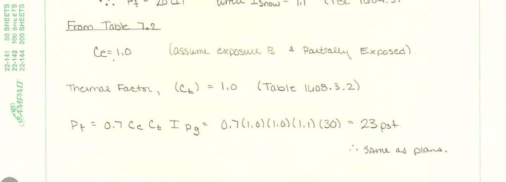
3 weight with 9 1/4 concrete topping at low point tapering to 3 1/4 at high point. o Steel construction type is partially restrained and semirigid framing. o Steel beams and slabs form a composite system using shear studs o 3 1/2 light weight concrete slab on galvanized composite steel deck in accordance with ASTM A o Concrete strength- All concrete to have a minimum compressive strength of 4000 psi. Pile capacity shall be designed for 250 kips axial + 8 kips lateral kips uplift unless otherwise noted on pile cap detail on this sheet. Structural Steel Materials W-Shapes ASTM A 992/A 992M Channels and Angles ASTM A 36/A 36M Plate and Bar ASTM A 36/A 36M Cool-Formed Hollow Sections ASTM A500, Grade B or C; Structural Tubing Steel Pipe ASTM A 53/A 53M, Type E or S; Grade B 3. Load Summary: Dead Loads: o Self weight of slab: 36 psf o Basement slab on grade: 6 = 55psf, 5 = 43.5psf o Self weight of steel: 10 psf o Exterior Wall: 40 psf of wall surface Superimposed Dead Loads: o Partitions: 20 psf o Mechanical: 10 psf o Ceiling: 15 psf o Fireproofing: 5 psf Live Loads: o Live Load Reduction factor has been utilized o Corridors, First Floor: 100 psf o Corridors, Second Floor and Above: 80 psf o Offices: 70 psf (50 psf plus 20 psf partition allowance) o Labs: 100 psf o Mechanical Rooms (excluding Air Handling Unit rooms): 250psf o Heavy Storage: 250 psf o Air Handling Unit Rooms: 150 psf Snow Load is based on the following: o Roof snow load of 23 psf o Snow Exposure Factor (Ce) of 1.0 o Snow Importance Factor (I) of 1.1
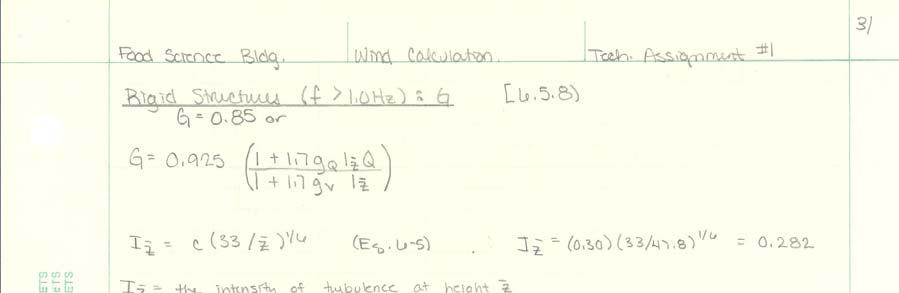
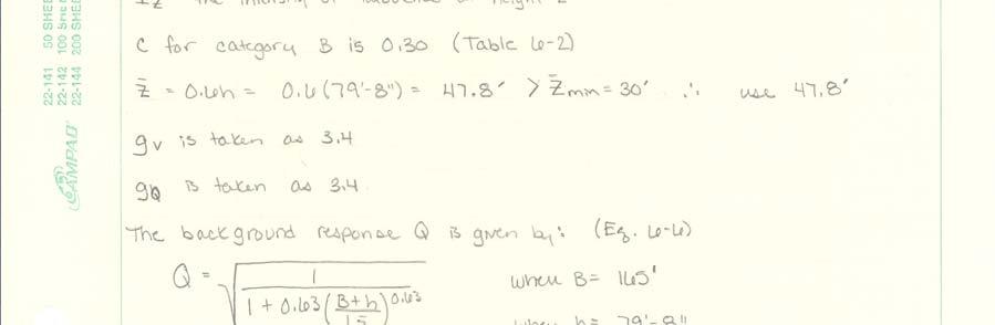
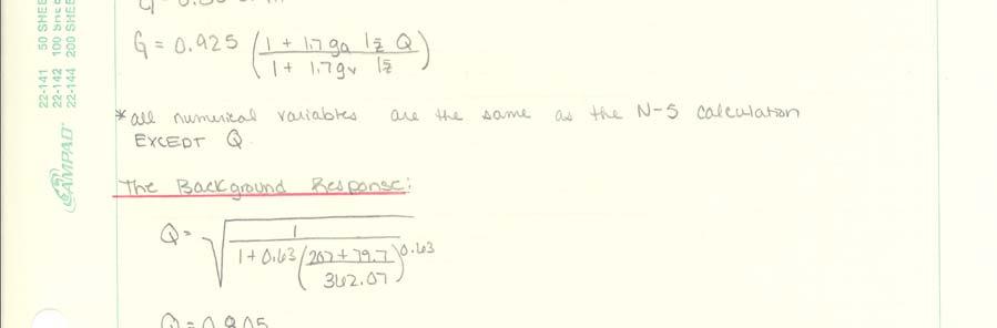
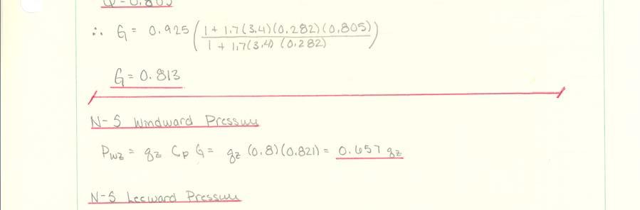
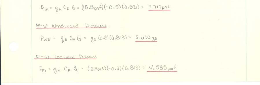
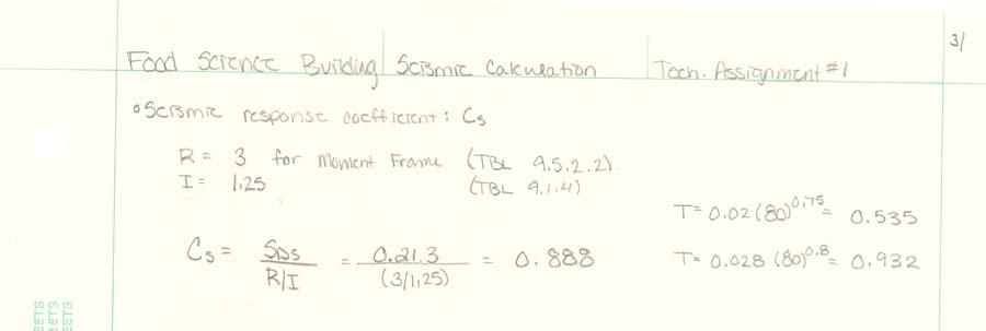
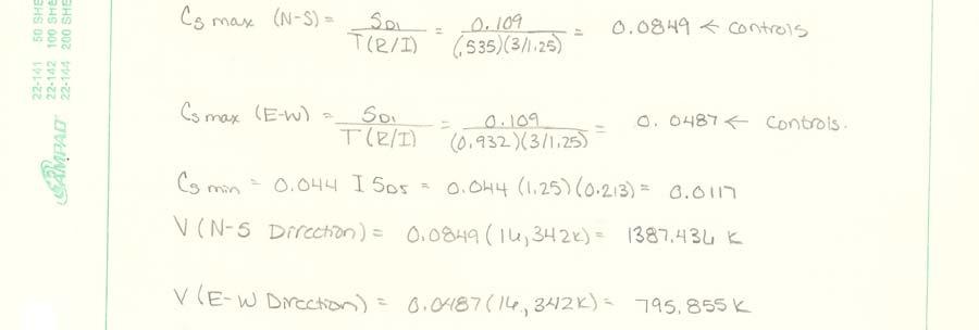
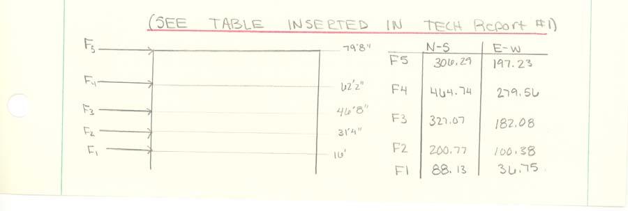
4 o Drift on lower roofs taper from 106 psf to 75 psf at 16ft. Wind Load has been calculated based on the following: o 3-second gust, 90mph o Importance factor (1) : 1.0 o Exposure- B o Maximum Windward Pressure = psf o Maximum Leeward Pressure = 7.71 psf Seismic Load has been calculated based on the following: o Site Class: D o Site-Adjusted Spectral Response Acceleration for 0.2 second pd. (Sms): 0.272g o Site-Adjusted Spectral Response Acceleration for 1.0 second pd. (Sms): 0.144g o Seismic Hazard Exposure Group 1 Vertical Distribution of Seismic Forces: Level w x h x w x h x (roof) w x h x C vx (N- S) C vx (E- W) F x (N- S) F x (E- W) Σ= Σ= Σ= Σ= Σ= Σ=
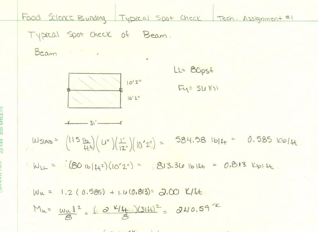
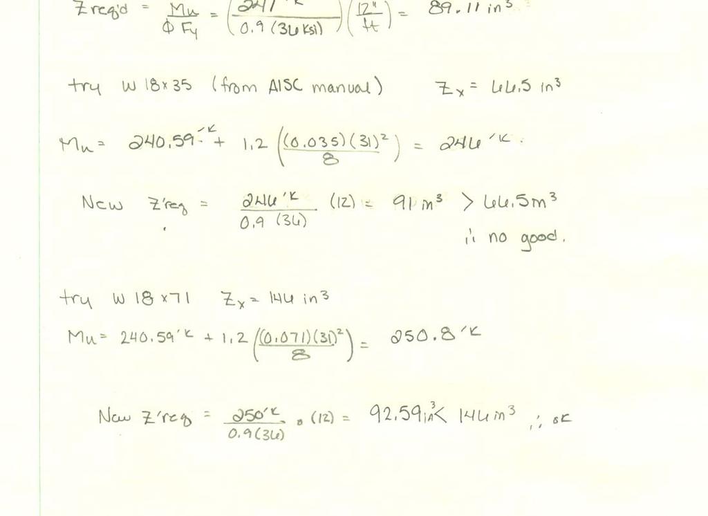
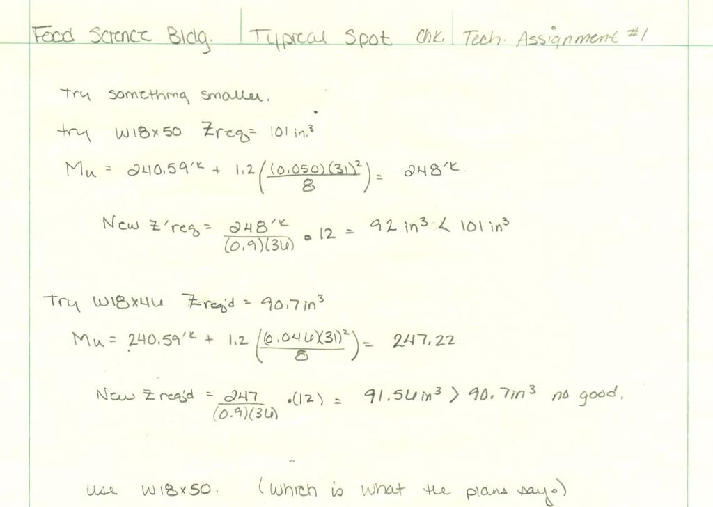
5 4. Typical Bay Spot Check
6
7
8 5. Appendix A. Building Sketches 1. First Level Framing and Foundation Plan West 2. Typical Slab Edge Detail 3. Second Level Framing Plan West 4. Second Level Framing Plan East 5. Third Level Framing Plan West 6. Concrete Double Tee s Section 7. Typical Cooler / Production Area Slab Detail at Masonry Wall 8. Third Level Framing Plan East 9. Fourth Level Framing Plan West B. Wind Calculation C. Seismic Calculation D. Snow Calculation


9 A. Building Sketches 1. First Level Framing and Foundation Plan West


10 2. Typical Slab Edge Detail


11 2. Second Level Framing Plan West


12 3. Second Level Framing Plan East


13 4. Third Level Framing Plan West


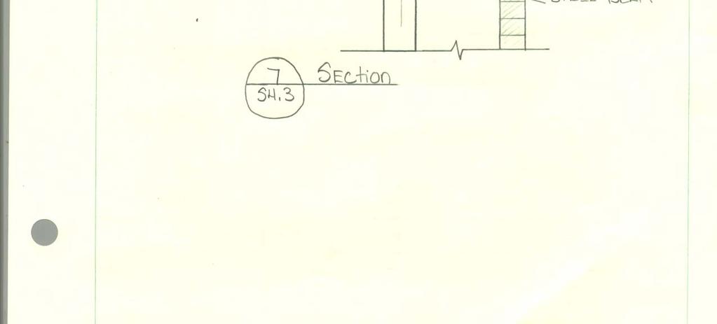
14 5. Concrete Double Tee s Section


15 6. Typical Cooler and Production Area Slab Detail at Masonry Wall


16 7. Third Level Framing Plan East


17 8. Fourth Level Framing Plan West
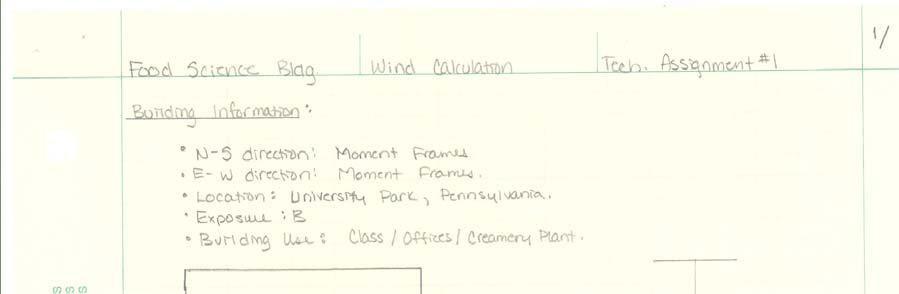
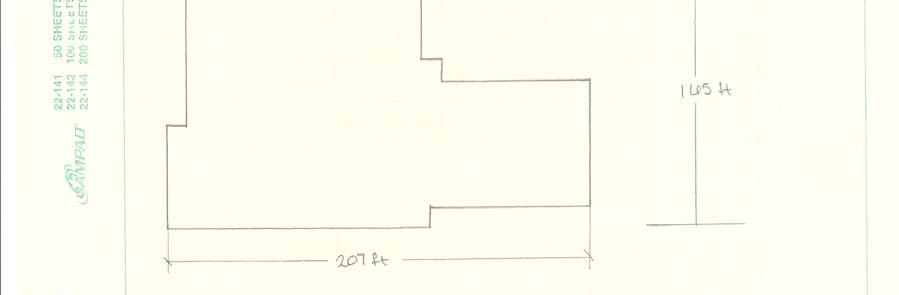


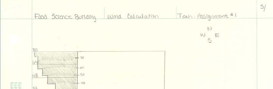
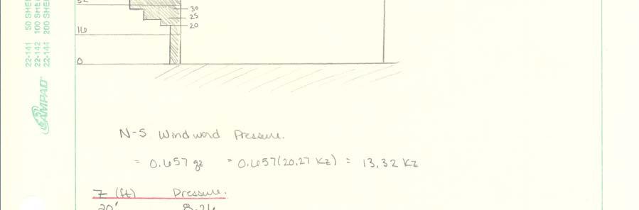
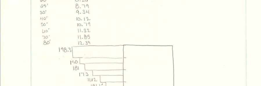
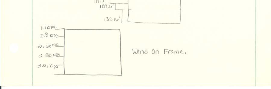
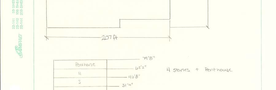
18 E. Wind Calculation
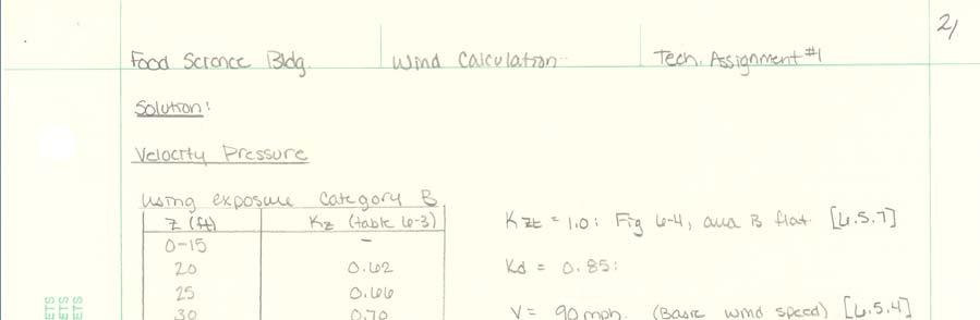

19

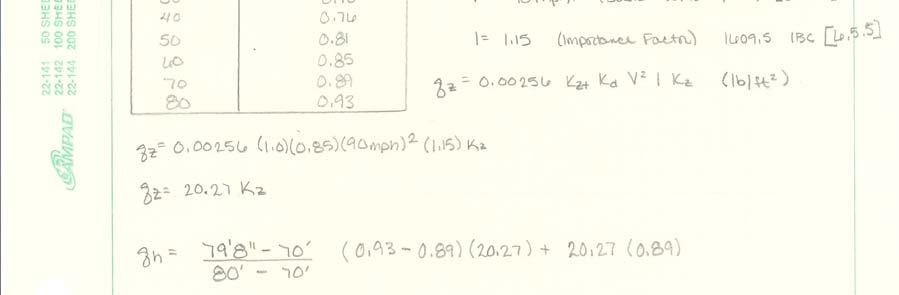
20

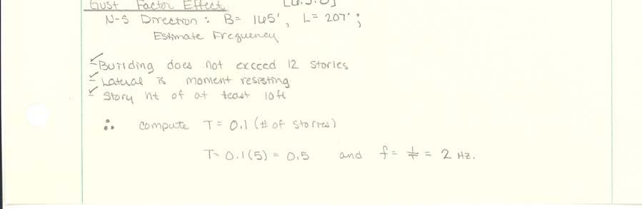
21
22

23 F. Seismic Calculation

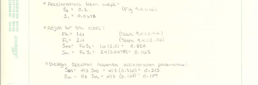

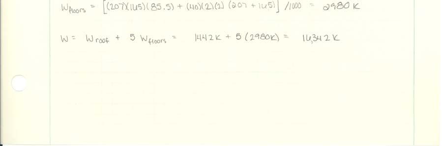
24
25
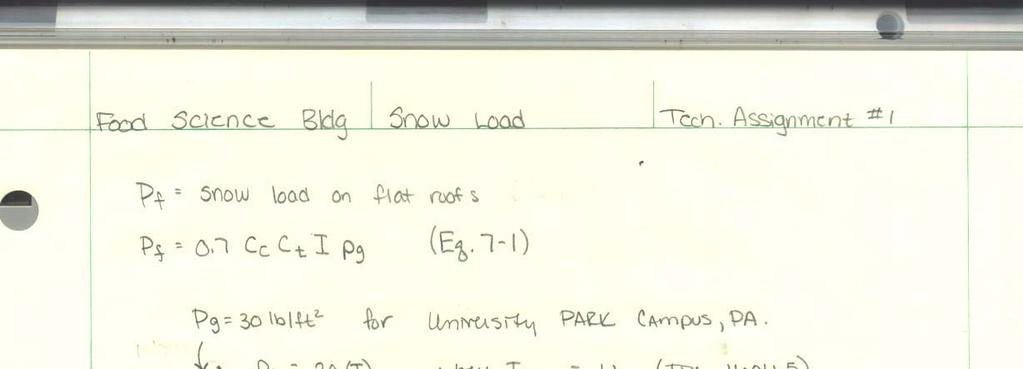
26 G. Snow Calculation