Cross-laminated timber Technical Data
|
|
|
- Gerald Hall
- 5 years ago
- Views:
Transcription

1 WHERE IDEAS CAN GROW. Cross-laminated timber Technical Data


2 WHERE IDEAS CAN GROW. Wood is naturally CO 2 -neutral and energy-efficient in all respects. As a building material, its positive properties help protecting against heat in summer and cold in winter. Its CO 2 -saving capacity significantly contributes to protecting our environment. If you use wood for building work you make a valuable contribution to the protection of the climate and the environment. In Austria, one cubic metre of new wood grows each second. One cubic metre of wood keeps one ton of atmospheric CO 2 and thus helps to reduce the burden on our environment. A mere 10% more wood constructions in Europe would be enough to save as much CO 2 as would be necessary to reach the Kyoto goals. As a PEFC-certified company, Mayr-Melnhof Holz largely processes spruce as well as fir, larch and pine. The wood mainly originates from the surrounding areas of the individual locations. 2
3 Products of Mayr-Melnhof Holz CONTENTS Glulam beams Duo-/Trio beams Laminated ceiling elements Mayr-Melnhof Holz 2-3 Technical data 4 Structure and loads 5 Basis of computation 6-7 Panel stress 8-9 Slab stress Fire protection 12 Structural pre-analysis Diagrams Construction details Notes Floor and wall beams Cross-laminated timber 3-ply structural panels Formwork panels Formwork beams Mayr-Melnhof Holz Holding AG Turmgasse Leoben Austria T F holding@mm-holz.com Esteemed Customer, Thank you for your interest in our products. Please note that this document is a sales brochure and that the quoted figures are merely reference values. The document may contain typing errors and other mistakes. In preparing this sales brochure, all information was researched with due diligence. However, we cannot accept any liability for the accuracy and completeness of the figures and data stated therein. Any legal claims due to the use of this information are therefore excluded. The content of the services we are liable for can only be defined by way of a written quotation in combination with our relevant written confirmation of your order. This sales brochure and our other sales materials are not quotations in a legal sense. For planning your project we recommend you get in personal contact with one of our members of staff who will be glad to assist you on a non-binding basis. Any copying of this material in full or in part requires the expressed approval of the MM Holz Group. 3
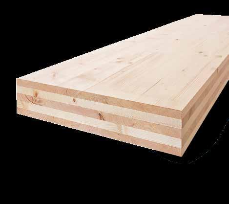
4 Technical data is a large-format solid wood board with a multi-layer, crosswise-oriented profile. Structure and manufacture Finger-jointed and planed lamellas are loosely laid next to each other and the flat surfaces of the layers glued at right angles to one another. The structure is made up of at least 3 layers and would typically have a symmetrical layout. The layers are pushed together laterally to dimension before applying pressure in order to obtain a gap-free surface. To avoid uncontrolled stress cracks, the narrow sides are not glued. Lamellas Technically dried, quality graded mechanically and according to optical criteria as well as finger-jointed. Strength classes of the lamellas C24/L25 according to EN % share of C16 / L 17 admissible (acc. to ETA-09/0036) Weight Approx. 480 kg/m 3 for determining the transport weight Wood moisture 12% (± 2%) Dimensional stability In longitudinal and crosswise slab level direction: 0.01% per % wood moisture change At a right angle to the slab level: 0.20% per % wood moisture change Gluing Depending on the requests of our customers we offer Melamine resin-based adhesive (MUF) or polyurethane adhesive (PUR). Both types of adhesive are approved for the gluing of load-bearing timber components according to the EN 301 type 1 standard. Usage classes has been approved for the usage classes 1 and 2 according to ETA 09/0036. Dimensions Format PUR up to max. 3.5 m x 16 m Format MUF up to max. 3.0 m x 16.5 m Strengths 60 mm to 280 mm Standard widths 2.40 m / 2.50 m / 2.65 m / 2.75 m 2.90 m / 3.00 m / 3.20 m / 3.50 m Technical approval European Technical Approval ETA-09/0036 Types of wood Primarily spruce (picea albies) from domestic forests; other types of wood available on request. Heat conductivity λ = 0.10 W/mK according to test report no. B TU Graz Heat storage capacity c = 1.60 kj/kgk Diffusion resistance μ = 60 (at 12% wood moisture) Air tightness From 80 mm 3s WSI or NSI air-tight according to test report no. B TU Graz or short report no. 575/2016-BB HFA Sound insulation Excellent sound insulation due to solid construction method. The values depend on the relevant wall and/or ceiling structures see tested sample wall structures at or in technical documentation. Reaction to fire According to EN 13501: D, s2, d0 Fire resistance and charring rate According to classification report by Holzforschung Austria, 1042/2012/04 and 1042/2012/01 for walls: 0.64 mm/min (medium charring rate for MUF gluing according to IBS Linz, 2009) for ceilings: 0.71 mm/min (medium charring rate for MUF gluing according to IBS Linz, 2009) 4
5 Structure and loads of CLT elements CLT elements and / or as slabs. can be exposed to loads as panels Panel stress Due to their structural profile, CLT elements have different levels of stiffness in orthogonal direction to each other (orthotropic panels). Slab stress: In case of stress in the direction of the panel level (slab stress), only panel layers with fibre directions running parallel to the observed direction of force may be taken into account. In order to determine their load-bearing characteristics during bending movements, only those panel lamellas are taken into account that run into the load-bearing direction. The cross-layers cannot transfer any longitudinal stress and are exposed to shear stress (rolling shear). The shear stress of the cross layers must be taken into account for identifying the load-bearing capacity as well as the deformation behaviour of CLT. 5
6 Calculation principles The dimensioning of CLT components made of can be performed according to EN and EN , taking account of Annexes 2 and 3 of ETA 09/0036. Principles and national specifications for the dimensioning of CLT are included in Annex K of ON B :2015. In any case, the dimensioning of CLT components must be performed under the responsibility of an engineer who is familiar with solid panel-shaped wooden construction elements. The stresses and resistances of the profile depend on the panel structure, the structural system as well as external influences. Possible dimensioning models for the double-axis load-bearing capacity of panels are the shear-flexible, orthotropic panels or the shear-flexible girder grid. In case of a dominant load-transfer direction, the top layers are oriented in this main load-bearing direction, providing them with considerably higher stiffness than in the secondary load-bearing direction. The calculation of the section forces and deformations is carried out on the one-dimensional panel strip. Suitable models for dimensioning this single-axis, spanned beam include the shear-flexible beam (Timoshenko beam), the shear analogy method and the γ-method (gamma method). The γ-method is an approximation method for practical construction work. It allows an engineering-based approach for taking shear deformations into account and to calculate with conventional truss programs. The cross-section value table (see adjacent page) contains the analysed, effective inertia moments of that depend on the span of the panels. The shorter the span, the larger the portion of the shear deformation and therefore also the reduction of the full inertia moment. In case of continuous girders, 4/5 th of the span must be assumed for the span in order to select the effective inertia moment. In case of cantilever beams, the double protruding length must be used. The section force and the deformation calculation, however, must be carried out with the actual spans and/or protruding lengths. The practical construction calculations with conventional truss programs can be performed with an effective width and the actual height of the full cross-section. The effective width results from the ratio of the effective inertia moment and the inertia moment of the full cross-section, multiplied by the actual width. The solution according to the γ-method is only precise for single-span girders with sinus-shaped uniformly distributed loads. High single loads and very short girder lengths in particular require a more precise calculation method. The calculation of the cross-section values according to the γ-method is described on the following pages. Calculation examples: Bemessung Brettsperrholz; Grundlagen für Statik und Konstruktion nach Eurocode, Wallner et. Al., 2013; ISBN The method is included in EN / Annex B and described for in ETA 09/0036 / Annex 3. It also forms the basis for the structural pre-analysis diagrams in this present folder. Similar to a bending girder, the calculation is carried out with flexible joining means. Instead of the flexibility of the joining means, however, the shear deformation of the cross layers is taken into account. In practical dimensioning, the effective moment of inertia (Ieff) is calculated. It is used to compute the section forces and deformations as for beams with a bending moment under rigid bond. 6

7 Cross-section values of panel types Total strength Structure (Bold = main load-supporting direction) A full A net I full (bxd 3 )/12 (depending on the span of a single-span girder) 1 m 2 m 3 m 4 m 5 m 6 m 8 m /I full /I full /I full /I full /I full /I full /I full [cm²] [cm²] [cm 4 ] [cm 4 ] [%] [cm 4 ] [%] [cm 4 ] [%] [cm 4 ] [%] [cm 4 ] [%] [cm 4 ] [%] [cm 4 ] [%] 60 3s s s s s s s s s s s s ss s ss s ss ss ss All data refers to a 1 m wide panel strip. A full A net I full total cross-section cross-section value for the proof of compressive strength values in the directions of the panel layers inertia moment of the full cross-section as comparative value effective inertia moment in the direction of the top layers for single-span girders / I full ratio indicating to what extent cross layers change the effective inertia moment of the cross-section 7
8 with ( ). with Panel stress For calculating the characteristic cross-section values, only panels may be taken into account that are arranged in the direction of the mechanical stress. For dimensioning construction components made of cross-laminated timber according to EN :2015 and B :2015 the characteristic strength values and elasticity constants of ETA 09/0036 / Annex 2 must be used (see table on the right-hand side). As regards multi-axis, spanned cross-laminated timber panels, different stiffness value in the orthogonal load-bearing directions must be taken into account. The effective rigidity depends on the effective inertia moment Ieff. The calculation of the effective inertia moment according to the --method based on EN / Annex B and ETA 09/0036/ Annex 3 is described below. This method only applies for 3-layer and 5-layer structures. For all further structures, the modified -method must be used. The effective inertia moment, however, can also be gathered from the cross-section value table (depending on its span) see previous page. Distances of centres of gravity: Flexibility factors The flexibility factors take account of the shear deformations of cross layers (rolling shear). The expression si/ki of the EN should be replaced by. 1,0 for symmetrical assembly General rule: For a 5-layer, symmetrical structure, the following applies: with: E1,3 = N/ mm² elasticity modulus for C24 G 9090 = 50 N/mm² rolling shear modulus for C24 l = applicable span The resistance modulus for the bending stress proof is calculated as follows: with ( ) t 1 t tot t 2 t t 1 3 t 2 b The shear stress proof (rolling shear strength) can be performed as follows:. with with single inertia moments of lengthwise layers i = 1-3 Surfaces of lengthwise layers (b = 1,0 m) For calculation examples, see cross-laminated timber dimensioning in Bemessung Brettsperrholz; Grundlagen fur Statik und Konstruktion nach Eurocode, Wallner et. Al., 2013; ISBN Lengthwise layers i = 1 3 8


9 Material key values of panel stress according to ETA-09/0036 Characteristic Numerical value Strength classes of boards Elasticity modulus: Parallel to the fibre direction of the boards E 0, mean 11, N/mm 2 At a right angle to the fibre direction E 90, mean N/mm 2 Shear modulus: Parallel to the fibre direction of the boards G 090, mean N/mm 2 At a right angle to the fibre direction of the boards, rolling shear modulus G 9090, mean N/mm 2 C24 Bending strength: Parallel to the fibre direction of the boards f m, k f m, k may be increased to 28.8 N/mm 2 for C 24 (f m, CLT, k ) after the above approval N/mm 2 Tensile strength: At a right angle to the fibre direction of the board f t, 90, k 0.12 N/mm 2 Compressive strength: At a right angle to the fibre direction of the board f c, 90, k 2.50 N/mm 2 Shear strength: Parallel to the fibre direction of the boards f v, 090, k 2.50 N/mm 2 At a right angle to the fibre direction of the board (rolling shear strength) f v, 9090, k 1.10 N/mm 2 9
10 Slab stress In case of stress on the panel level, we must distinguish between the below models. Girder dimensioning of board layers in stress direction of board layers at a right angle to the stress direction Maximum with Design value of shear force For dimensioning cross-laminated timber elements as girders placed in upright positions, the following equations may be used on the conditions of the technical column theory. Bending strength and bending stiffness may be calculated with the full cross-section of the board layers in the load-bearing direction. For calculating shear stress, the net surface with the smaller cross-section of the two load-bearing directions is decisive. t 2 t 1 H t3 t2 t 1 10
11 Slabs as buckling bar For dimensioning cross-laminated timber elements as buckling bars, only lamella layers in parallel to the direction of force must be taken into account. The buckling analysis can be carried out taking account of the cross-sectional structure according to the equivalent member method set forth in EN :2015. The slenderness must be limited to = 150. Ceiling and wall slabs CLT elements are used to build shear areas in ceilings and walls. R The shear stress due to slab shear stress can be calculated according to B :2015. Material key values of slab stress according to ETA-09/0036 Characteristic Strength classes of panels Numerical value C24 Elasticity module: Parallel to the fibre direction of the boards E 0,mean 11, N/mm 2 Shear module: Parallel to the fibre direction of the boards G 090,mean N/mm 2 Bending strength: Parallel to the fibre direction of the boards f m,k N/mm 2 Tensile strength: Parallel to the fibre direction of the boards f t, 0, k N/mm 2 Compressive strength: Parallel to the fibre direction of the boards f c, 0, k N/mm 2 Shear strength: Parallel to the fibre direction of the boards f v, 090, k 5.00 N/mm 2 11
12 Fire protection By using kclt elements, high requirements with regard to the fire resistance of ceilings and walls can be fulfilled. In order to proof the load-bearing capacity in case of a fire, the residual cross-section of a component according to the required fire resistance time must be referred to. This proof must be given in the extraordinary dimensioning situation according to EN with the method of a reduced cross-section. In addition, a layer thickness of d0 = 7 mm (with reduced strength and stiffness) must be discounted from this cross-section. Charring rates In order to establish the applicable charring rates of, the charring behaviour as a function of the gluing of the elements must be taken into account. Elements with melamine resin glue (MUF) show an even charring behaviour. The average charring rate across several layers can usually be stated with the following value: Ceiling, roof β 0 = 0.71 mm / min Proof of fire resistance of based on classification reports Cross-laminated timber elements as load-bearing components were tested by the IBS in Linz, where large-scale fire tests were performed. Under standardised test conditions (span, test load, etc.), cross-laminated timber elements were classified into the fire resistance classes of REI 30 to REI 120. See also Classification Reports. An uncovered CLT ceiling e.g. with 160 mm / 5s meets the requirements of fire resistance class REI 90. An uncovered CLT wall with 100 mm / 3s meets the requirements of fire resistance class REI 60, on the condition of charring on one side and under test conditions. Panelling and facing shells further improve the fire resistance of CLT elements. In case of any deviation from the framework conditions of the tests due to certain building-related aspects, such as e.g. span, element height or load, any proof of fire resistance can be provided according to ON EN and ON B , taking account of the above-referenced charring rates. Wall β 0 = 0.64 mm / min In case of elements with polyurethane glue (PUR) the glue joint will soften due to the increased temperature. As a consequence, the charred layer will chip off. In case of continued charring, the next board layer will be charred twice as much until a carbon layer of about 25 mm will form (see planning folder Building with Cross-Laminated Timber in Multi-Storey Constructions by the HFA). In identifying the remaining cross-section, this charring behaviour can be taken into account as suggested by the HFA: Ceiling, roof Top layer From the 2 nd layer for the first 25 mm For the rest of the layer Wall Top layer From the 2 nd layer β 0 = 0.65 mm / min β 0 = 1.30 mm / min β 0 = 0.65 mm / min β 0 = 0,65 mm / min β 0 = 0,90 mm / min 12
13 Pre-measurement diagrams General information The applicable verifications are based on ETA- 09/0036 and EC 5 (EN1995-1:2015 and B :2015). The stated diagrams are intended to be used for pre-measurement and do not replace static calculations. The wall elements top layer is vertical. Static system: Wall N k Assumptions to determine the required wall panel Loads refer to 1.0 m of wall length. w k = wind load at right angle to the wall [kn/m 2 ] N k = N Gk + N Qk [kn/m] N Gk = Vertical load resulting from dead weight [kn/m] N Qk = Vertical load resulting from category A,B live load [kn/m] Restriction: N Gk 3/4 * N k w k = 1.0 kn/m 2 h = l k wall under vertical load 1, s 100 5s 100 3s 120 5s 120 3s 140 5s 160 5s Load N k [kn/m] Span [h] 13
14 Pre-measurement diagrams General information The applicable verifications are based on ETA- 09/0036 and EC 5 (EN1995-1:2015 and B :2015). The stated diagrams are intended to be used for pre-measurement and do not replace static calculations. The elements span direction is parallel to the top layer. Static system: Single span beam - roof Assumptions to determine the required wall panel Utilisation class 2 k def = 1.0 The board s dead weight is taken into account in the diagram. q k = g 2k + s k [kn/m²] g 2k = roof structure [kn/m²] s k = snow load on the roof [kn/m²] for h s 1,000 m -> k mod = 0.90 Restriction: g 2k 0.50* q k s k g 2k L Load q k [kn/m²] s 80 3s 90 3s 100 5s 100 3s 120 5s 120 3s 140 5s Span L [m] Load q k [kn/ m²] s 220 7s 180 5s 200 5s 200 7ss 220 7ss 240 7s 240 7ss 260 7ss 280 7ss 4 4,5 5 5,5 6 6,5 7 7,5 8 8,5 9 9, Span L [m] 14
15 Pre-measurement diagrams General information The applicable verifications are based on ETA- 09/0036 and EC 5 (EN1995-1:2015 and B :2015). The stated diagrams are intended to be used for pre-measurement and do not replace static calculations. The elements span direction is parallel to the top layer. Static system: Single span beam - ceiling Assumptions to determine the required wall panel Utilisation class 1 k def = 0.8 The board s dead weight is taken into account in the diagram. q k = g 2k + n k [kn/m²] g 2k = roof structure [kn/m²] n k = Category A,B live load [kn/m 2 ] -> k mod = 0.80 Restriction: g 2k 2/3 * q k The diagrams take into account a simplified vibration verification! n k g 2k L Load q k [kn/m²] s 80 3s 90 3s 100 5s 100 3s 120 5s 120 3s 140 5s Span L [m] s 180 5s 200 5s 200 7ss 220 7s 240 7s 240 7ss 260 7ss 220 7ss 280 7ss Load q k [kn/m²] ,5 5 5,5 6 6,5 7 7,5 8 8, Span L [m] 15
16 Pre-measurement diagrams General information The applicable verifications are based on ETA- 09/0036 and EC 5 (EN1995-1:2015 and B :2015). The stated diagrams are intended to be used for pre-measurement and do not replace static calculations. The elements span direction is parallel to the top layer. Static system: Dual span beam - roof Assumptions to determine the required wall panel Utilisation class 2 k def = 1.0 The board s dead weight is taken into account in the diagram. q k = g 2k + s k [kn/m²] g 2k = roof structure [kn/m²] s k = snow load on the roof [kn/m²] for h s 1,000 m -> k mod = 0.90 Einschränkung: g 2k 0.50* q k s k g 2k L L Load q k [kn/m²] s 80 3s 90 3s 100 5s 100 3s 120 5s 120 3s 140 5s 2 2,5 3 3,5 4 4,5 5 5,5 6 6,5 7 7, Span L [m] Load q k [kn/m²] s 180 5s 200 5s 200 7ss 220 7s 220 7ss 240 7s 240 7ss 260 7ss 280 7ss Span L [m] 16
17 Pre-measurement diagrams General information The applicable verifications are based on ETA- 09/0036 and EC 5 (EN1995-1:2015 and B :2015). The stated diagrams are intended to be used for pre-measurement and do not replace static calculations. The elements span direction is parallel to the top layer. Static system: Dual span beam - ceiling n k g 2k Assumptions to determine the required wall panel Utilisation class 1 k def = 0.8 The board s dead weight is taken into account in the diagram. q k = g 2k + n k [kn/m²] g 2k = roof structure [kn/m²] n k = Category A,B live load [kn/m 2 ] -> k mod = 0.80 Live load is assumed to be unfavourable by field. Restriction: g 2k 2/3 * q k The diagrams take into account a simplified vibration verification! L L Load q k [kn/m²] s 80 3s 90 3s 100 5s 100 3s 120 5s 120 3s 140 5s 2 2,5 3 3,5 4 4,5 5 5,5 6 6, Span L [m] Load q k [kn/m²] s 220 7ss 180 5s 200 5s 200 7ss 240 7s 240 7ss 260 7ss 220 7s 280 7ss,5 5 5,5 6 6,5 7 7,5 8 8,5 9 9, Span L [m] 17
18 catalogue AW 01 outside inside Exterior wall / with wooden facade / not back-ventilated / without installation level from the outside in Wood - larch 20.0 Wood battens - spruce 30/ Breathable foil SD 0.3 m Wood fibre insulation board s or 5s GKF 12.5 mm REI 90* > 42 db 0.21 W/m 2 K AW 02 outside inside Exterior wall / with wooden facade / not back-ventilated / with installation level from the outside in Exterior wall pannelling 20.0 Wood battens - spruce 30/ Breathable foil SD 0.3 M perhaps gypsum fibreboard 15.0 Wood fibre insulation [0.039] Wood battens - spruce 60/200 Battens - spruce 60/60 on resilient bracket rock wool 50 GKF 12.5 mm or gypsum fibreboard (10 mm) s or 5s REI 90* 53 db 0.19 W/m 2 K outside AW 03 inside Exterior wall / with plaster facade / not back-ventilated / with installation level from the outside in Plaster 4.0 Rock wool MW-PT Plaster base board s or 5s Battens - spruce 40/50 on resilient bracket Glass wool [0.040] D = 50 mm REI 120* 53 db 0.20 W/m 2 K GKF mm or gypsum fibreboard (2 10 mm) 25.0 AW 04 outside inside Exterior wall / with plaster facade / not back-ventilated / without installation level from the outside in Plaster 4.0 Rock wool MW-PT Plaster base board s or 5s REI 60* > 38 db 0.20 W/m 2 K 18 Source: Catalogue of «Bauphysikalisch geprüfter Bauteile für den Holzbau» ( timber construction components tested in terms of building physics ) *acc. to Holz Forschung Austria classification report, EN : REI 30 - REI 120
19 catalogue Flat partition wall / without installation level from left to right 3s or 5s Footfall sound insulation board MW-T s or 5s REI 60* 48 db 0,39 W/m 2 K WTW 01 outside inside Flat partition wall / without installation level from left to right GKF 12.5 mm s or 5s Footfall sound insulation board MW-T s or 5s GKF 12.5 mm REI 90* 56 db 0.38 W/m 2 K Structure without GKF boards 230 REI 60* 48 db 0.39 W/m 2 K WTW 02 outside inside Flat partition wall / with installation level from left to right GKF 12.5 mm s or 5s Footfall sound insulation board MW-T s or 5s Wood battens - spruce 40/50 on resilient bracket glass wool [0.040] D = 50 mm 50.0 GKF 12.5 mm REI 90* 62 db 0.27 W/m 2 K WTW 03 outside inside Flat partition wall / with installation level WTW 04 from left to right GKF 12.5 mm 12.5 Rock wool [0.04; R = 27] D = 60 mm Wood battens - spruce 40/50 on resilient bracket 70.0 inside inside 3s od. 5s Wood battens - spruce 40/50 on resilient bracket 70.0 Rock wool [.04] D = 60 mm 265 REI 90* 58 db 0.25 W/m 2 K GKF 12.5 mm 12.5 Source: Catalogue of «Bauphysikalisch geprüfter Bauteile für den Holzbau» ( timber construction components tested in terms of building physics ) *acc. to Holz Forschung Austria classification report, EN : REI 30 - REI
20 catalogue IW 01 Interior wall / without installation level from the outside in 3s or 5s REI 60* 33 db 1.1 W/m 2 K IW 02 Interior wall / without installation level from the outside in GFK 2 x 12,5 mm s 80.0 GFK 2 x 12,5 mm REI 60* 38 db 0.87 W/m 2 K FD 01 Flat roof / suspended / not back-ventilated outside from the outside in Fill (grit) 50.0 Separating fleece [SD 0.2M] Extruded polystyrene 80.0 Bituminous felt 9.0 inside Rock wool [0.040] Vapour barrier SD I500M ceiling 5s or acc. to static requirements REI 90* 47 db 0.12 W/m 2 K Wood battens - spruce suspended Glass wool [0.040] D = 50 mm 70.0 GKF board 12.5 FD 02 outside Flat roof / suspended / not back-ventilated from the outside in Fill (grit) 16/ Separating fleece - Roofing membrane 2.0 Mineral fibreboard (2 x 100 mm) ( = 0.045) REI 60* 44 db 0.18 W/m 2 K Vapour barrier - inside 5s Source: Catalogue of «Bauphysikalisch geprüfter Bauteile für den Holzbau» ( timber construction components tested in terms of building physics ) *acc. to Holz Forschung Austria classification report, EN : REI 30 - REI 120
21 catalogue Ceiling / dry / not suspended GD 01 from top to bottom Gypsum fibreboard 10.0 Heraklith floor (gypsum fibre board) 10.0 Heraklith floor (wood wool building board) Heralan TPS 15/13 footfall sound insulation Fill (grit) 50.0 Trickle protection foil 5s or acc. to. static requirements REI 90* 65 db Footfall sound L ntw 50 db 0.38 W/m 2 K Ceiling / wet / suspended GD 02 from top to bottom Cement screed 60.0 PE foil (separating layer) Footfall sound insulation board TDPS Fill (grit) unbounded (2/4) 30.0 PE foil (trickle protection) - 5s Suspended ceiling CD profile 60 x 27 Air 10 mm MW 60 mm REI 90* 62 db Footfall sound L ntw 46 db 0.25 W/m 2 K Gypsum plasterboard 12.5 Ceiling / wet / not suspended GD 03 from top to bottom Cement screed 60.0 PE foil (separating layer) Footfall sound insulation board TPS 30.0 Fill (grit) unbounded (xy 2/4) 60.0 PE foil (trickle protection) - 5s REI 60* 60 db Footfall sound L ntw 57 db 0.44 W/m 2 K Source: Catalogue of «Bauphysikalisch geprüfter Bauteile für den Holzbau» ( timber construction components tested in terms of building physics ) *acc. to Holz Forschung Austria classification report, EN : REI 30 - REI
22 22 Notes
23 Notes 23
24 FA S C H I N G B A U E R & S C H A A R 6 Locations 3 Sawmills 3 Timber processing plants 2 Pellets production sites 1 Briquette production Efimovskij Russia (Sawmill) Richen (Timber processing plant, briquettes) Paskov (Sawmill, pellets) Germany Czech Republic Leoben Austria (Sawmill, pellets) Reuthe (Timber processing plant) Gaishorn am See Your local contact Mayr-Melnhof Holz Gaishorn GmbH Nr Gaishorn am See Austria T F gaishorn@mm-holz.com Mayr-Melnhof Holz Reuthe GmbH Vorderreuthe Reuthe Austria T F reuthe@mm-holz.com Mayr-Melnhof Holz Richen GmbH Römerstraße Eppingen-Richen Germany T F richen@mm-holz.com /8 Version 2016/01 Photos: morgenstern.com, koller-fotografie.at, archives ashley-studio.com, Mayr-Melnhof Holz Archiv Back: goesslersailer.at (Timber processing plant)