Solutions for the Construction of steel bridges using the example of the Hochmoselübergang
|
|
|
- Hope Hopkins
- 5 years ago
- Views:
Transcription

1 Solutions for the Construction of steel bridges using the example of the Hochmoselübergang Dipl.-Ing. Michael Hagedorn, Eiffel Deutschland Dr.-Ing. Thomas Klähne, Klähne Ingenieure Dipl.-Ing. Uwe Heiland, Eiffel Deutschland 1
2 Content General Overview Tender Project Construction of the Superstructure Preassembly Sliding Technology Statical Calculations Conclusions th Japanese-German Bridge Symposium, Munich, Germany 2


3 Overwiew Integration of the Hochmoselbridge in the existing road network 3

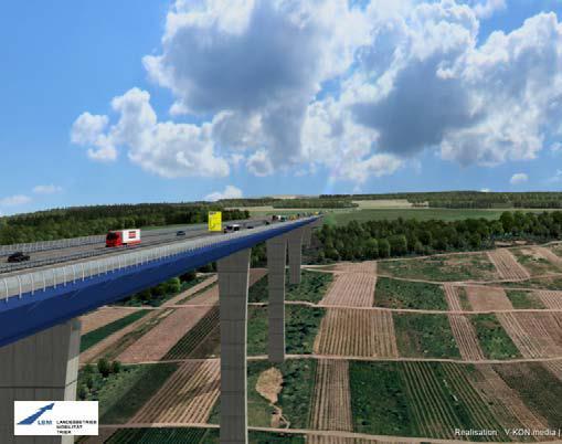
4 Overview Visualisation of the bridge 4
 Coating Area: 130.")
5 Overview Building consortium and volumina Construction Joint Venture: Eiffel Deutschland Stahltechnologie GmbH Porr Deutschland GmbH Contracted Services (net) Steel Construction: 85,4 Mio. Reinforced Concrete: 22,7 Mio. Contracted Amount: 108,1 Mio. Eiffage Construction Metallique Frankreich Tendered Quantities: Superstructure: Steel Structure: to (S 355) Coating Area: m² (outer surface), m² (inner surface) Total Area: m² Substructures Piles Ø 1,80 m: lfd. m mit 325 to BSt 500 S Concrete Volume: m³ Reinforcing Steel: to BSt 500 S 5
6 Tender project View of the Hochmoselbridge Number of superstructure fields: 11 Total length: 1702,35 m Max. height above valley: about 158 m 6
7 Tender project Normal cross section Cross section: 2 x footway 2 x road median strip Nominal width: 28,50 m Bridge deck area: m² 7
8 Tender project Substructures Pier 8 Substructures 2 box shaped abutments 10 piers Piers foundations with bored piles (diameters of 1,50 m to 2,00 m) single-celled hollow cross section pier head from 20,78 m up to 150,72 m shape defined by tapering 8
9 Tender project Construction method Construction method: incremental launching method Steel construction is premounted behind the eastern abutment Use of pylon cables and an 80 m high pylon for reduction of bending moments 9
10 Construction project Arrangement into shots Superstructure is divided into 82 shots Length of the shots: appr. 10 up to 25 m Below: example of arrangement for the first 3 fields 10
11 Construction project Arrangement of components Superstructure is divided into 12 components (height exceeds 6,00 m) Height variation is realised by components 9.1 and 9.2 Components weights varies between 20 and 100 tons 11
12 Construction project Different systems of transversal elements Cross frames (QR) Cross frames bracings (QRV) Transverse bracing (QV) Pier transverse system (PS) 12


13 Assembly Preassembly shots 1-3 and transport Preassembly of orthotropic plate with web (component 4) in the manufacturing plant of EDS Transport to the building site (component 6) 13


14 Assembly Preassembly yard 2011 and
15 Assembly Preassembly of superstructure Assembly of the hollow box in the preassembly yard and lying on edge 15


16 Assembly Preassembly of components Assembly of box web and parts of bottom and orthotropic plate Erection of preassembled side walls with parts of bottom and ortotropic plate 16

17 Assembly Preassembly of bottom part Assembly of the bottom plate shot 3 in
18 Assembly Sliding of superstructure using an stationary, central drive Horizontal forces due to friction on the sliding bearings on the piers Stability of the piers cannot be realised 18
19 Assembly Sliding of superstructure with decentralised drive Horizontal forces are shorted : action force (by hydraulic press) = reaction force (friction on the sliding bearings) 19


20 Assembly Sliding rocker with bridge sliding system 2011 Hydraulic presses Sliding layer 20
21 Bridge Sliding System 2011 mode of operation BVS
22 Bridge Sliding System 2011 mode of operation BVS
23 Bridge Sliding System 2011 mode of operation BVS
24 Bridge Sliding System 2011 mode of operation BVS
25 Bridge Sliding System 2011 mode of operation BVS
26 Bridge Sliding System 2011 mode of operation BVS
27 Bridge Sliding System 2011 mode of operation BVS
28 Bridge Sliding System 2011 mode of operation BVS
29 Bridge Sliding System 2011 mode of operation BVS
30 Bridge Sliding System 2011 mode of operation BVS

31 Bridge Sliding system
32 Calculation Modelling of overall system in final state and state of construction Superstructure and piers were modelled in the overall modell One-beam 3 D model with corresponding section properties in all directions This modelling has been chosen to meat the acceptabel calculation duration State of construction Final state 32
 Subsoil movements Drifting loads as a result of the tilted position of the piers Wind effects Bearing friction and bearing")
33 Calculation Load assumptions General The following effects are considered for calculation: Permanent influences (dead loads and additional loads) according to DIN Technical Report 101 Traffic influences (LM 1, LM 2, LM 3 according to DIN Technical Report 101) Subsoil movements Drifting loads as a result of the tilted position of the piers Wind effects Bearing friction and bearing replacement Subsequent removal and installation of asphalt Military traffic loads (MLC) Earthquake loads Load Model 1 (DIN Fachbericht 1) 33
34 Calculation Wind load assumptions The wind load on the superstructure consists of a horizontal, vertical and a torsional component. The application of the wind load on the bridge is as follows: Average velocity pressure q m Peak velocity pressure q b 34


35 Calculation Wind cover in shots 1 to 4 Due to the high wind load assumptions the stability is not given for superstructure in different sliding states and some free piers in intermediate construction conditions Therefore must be arranged cubes on the respective piers triangular wedges covered with sheet metal in the first 90 m of the cantilever end 35
36 Calculation Distribution of bending moments during construction 36
37 Calculation Maximum bending moments in the state of construction and final state 37

38 Calculation Interaction of sliding rockers and superstructure Spannung unter Gleichlast Laststeigerungsfaktor (SF) neu anzunehmende Bemessungsspannung in Prozent inkl. Sicherheitsfaktor t Blech 40 t Blech <40 mm t Blech 40 mm t Blech <40 mm mm % - - % % Steife ,00 1, Feld IV 50 1,00 1, Steife ,05 1, Feld III 80 1,10 1, Steife ,15 1, Feld II 95 1,20 1, Feld I 100 1,30 1,


39 Calculation Modelling of the transverse bracing and frames Modeling Transverse bracing (QV) Modeling Pier transverse system (PS) 39


40 Calculation Modelling of the pylon Main Assumptions Calculation according to II. order theory with use of global imperfections H/500 Load and boundary conditions according to global calculations of whole structure Submodelling used to detailed calculations of main parts of structure of pylon i.e. pylon head, pylon foot, joints, etc. Material: S235 (Pylon), S355 (pylon head, pylon foot, etc.) pylon head pylon joint pylon foot 40


41 Calculation Modelling the Erection processes of the pylon The Erection process carried out in two phases: Phase 1 (angles 0-45 o ) erection with use of additional pylon located at the foot of main pylon Phase 2 (angles 45 o- 90 o ) erection with use of tensioning station located at the bridge deck Phase 1 (angles 0-45 o ) 41
 tensioning station")
42 Calculation Modelling the Erection processes of the pylon Phase 2 (angles 45 o -90 o ) tensioning station 42


43 Calculation Results for the pylon Main structure Pylon head Pylon joint Pylon foot N [kn] M [knm] Q [kn] 43
44 Conclusions Construction of Hochmosel bridge is associated with further developments concerning the erection technology and static construction solutions This includes the patented sliding system BVS 2011 the vertical manipulation of the auxialary pylon for the variation of cable forces the shapes defined for the superstructure cantilever and pier heads as a result of wind tunnel investigations the concept of statical analysis for the global and functional subsystems 44

45 Sliding process 45

46 Sliding process 46


47 State 2014 Thank you for your attention 47